1
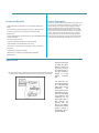
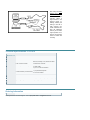
ETP1010 10BaseT Fault Tolerant Transceiver Features & Benefits Product Description The ETP1010 is an Ethernet* Fault Tolerant Transceiver, that offers a level of connectivity protection for your network. The ETP1010 allows you to replace a single segment of cable, between two network devices, with two segments of cable placed through different geographical paths, to ensure data - Nine switches to configure the ETP1010 to your specific needs. transfer protection should one cable be faulty, cut, damaged - Fourteen LEDs to give a comprehensive readout of data or pulled. That means to say the chances of your network transmissions. segment going down due to accidental damage are halved. - User selectable priority channel and hunt speed selectable between The ETP1010 is equipped with one AUI port and two RJ45s with an automatic hunt feature between the UTP channels. 2.5 and 10 seconds. - Dual RJ45 ports for transmission on two separate twisted pair cables. - No power supply required. - Provides redundant data path with a second cable. - Adds reliability to the weakest link in the chain. - Assurance of continuing communications in case of accident or wiring fault. - Rugged high strength steel casing. - IEEE 802.3, FCC Class A and VDE Class B compliant - Made in USA Applications The fault tolerant function makes this unit ideal for medical, banking, industrial control, security and military applications where signal integrity is essential. ETP1010 can be used to install two cables between a server and two ports on a hub or two separate hubs on the same backbone, allowing for a fault tolerant redundant path. Two ETP1010s can be used for installation of a redundant path cable. Both will be transmitting and receiving data, but for simplification, let's just look at the data going in one direction. The transmitting unit will always pass data on both channels, the receiving unit only does on one channel and when this channel samples inactivity it automatically flips to the other channel. Note: Using our Model EMC02 UTP to Fiber media converters on one or both of the channels, allows a large increase in the segment length, by allowing twisted pair cabling to link with a Fiber segment. Our media converters also have the advantage that they do not add a logical repeater count, and they are specially cased to enable wall mounting. Technical Specifications - ETP1010 ETP1010 Ethernet* v 2.0 AUI: One Male DB15 Interface UTP: 2x RJ45 LEDs AUI: Four Squelch, Transmit, Collision & Power Receive, Polarity, Link, Jabber & Enable (5 LEDs each channel) UTP: (Channel A & B) Switches AUI Port:(4 Position DIP) A & B Channels (4 Position DIP) Weight 1) A or B Primary channel Selection 2) SQE / HBE 3) 2.5 or 10 second selection 1) & 3) Reduced Squelch 2) & 4) Link Enable 13 oz. Dimensions 6.9" (175mm) x 2.8" (71mm) x 0.8" (20mm) Environmental Operating Temperature Operating Temperature: +5 to +55 C EMI & Safety FCC Class A, CE Ordering Information ETP1010 Fault Tolerant 10BaseT Transceiver Ordering Hotline & Technical Support - Tel: +1 (510) 440- 0242 [email protected] EtherCom ETP1010 Fault Tolerant 10BaseT Transceiver Application Notes These notes supplement the User’s manual and the data sheet for the subject device. Backup Data Communications Link The AUI port on the ETP1010 is connected to a work station or other network device. Having 2 RJ45 ports provides a backup communication link within a given loop in a 10Mbps Ethernet LAN. The backup linkage is achieved by connecting a second set of 10BaseT cabling to the backup RJ45 port of the transceiver, with the connections at the other end of the 2 sets of cables being on the same loop. (Note: if the connections on the other end of the two sets of cables are not on the same loop, collisions will be induced and network integrity will be lost.). See the network configuration examples below for further clarification. Primary Port Selection The ETP1010 will transmit and receive through only one of the two RJ45 ports during any given communication. The user selects which of the 2 ports will be the primary by switching the “A/B” switch to either A or B. Automatic switching During data communication, data is considered valid by the transceiver when it senses a valid Ethernet carrier and a link Integrity Pulse. When both ports have valid data, the transceiver will automatically choose to operate through the primary port. When the primary port does not have any valid data during a “quiet period”, and the backup port has valid data, the transceiver will automatically switch communication through the backup port. After a “quiet period” at the backup port previously in use, or if there is no valid data at either port, the transceiver will begin “hunting” for data by switching back to the primary port and then back to the backup port, and will continue switching back and forth between the two ports, until it senses valid data at either port, at which time it will enable that port. The transceiver will automatically enable the primary port when both ports have valid data. The switching search is for data is stopped when valid data is sensed at a given port for a period equal to the “valid carrier period”, except that the transceiver will attempt to re link the primary port after a quiet period on the previously enabled backup port, if the last valid data were on the backup port. The “valid carrier period” is equal to the “quiet period” and is programmed by the user for either 2.5 or 10 seconds by selecting either the 2.5 or the 10 second position on the “2.510” switch on the device. Manual Switches The ETP1010 has nine switches to provide the user with the options described below. The 4 position switch on the left side of the top surface is: A/B Sets either port A or port B as primary receive/transmit port. There is only one A/B switch per transceiver (position 1). SQE Enables SQE testing. Should be in off position for operation (normal position upon receipt from factory). There is one SQE switch per port transceiver (position 2). 2.5-10 Sets either 2.5 or 10 second delays as the “quiet period” prior to switching to alternate port, and as “valid carrier period” prior to stopping switching search for data. This switch establishes the delays for both ports as well as for both the quiet and the valid carrier periods. There is only one 2.5-10 switch per transceiver (position 3). Note: The 4th position in the 4 position switch on the left side of the top surface is disconnected. The 4 position switch on the right side of the top surface is: Reduced squelch There are 2 Reduced Squelch switches: on per RJ45 port (positions 1 and 3). The switch should be normally off for up to 100m meters of unshielded twisted pair to the port. Turn on for shielded twisted pair or for obtaining distance greater than 100 meter transmission range for unshielded twisted pair. This latter condition occurs when the network is “out of spec” (for max. wiring distances); network integrity is at risk when greater than 100 meter unshielded twisted pair segment lengths are used, although the ETP1010 will typically accommodate distances up to 150 meters of unshielded twisted pair if the Reduced Squelch is on. This out of spec condition is not recommended. Link There is a link switch for each port (positions 2 and 4). Turn on for testing purposes only, during which the automatic searching for link integrity is disabled. Turn off for normal operation to enable automatic switching. Configuration Examples There are two-position switches on the front surface (adjacent to RJ45 ports). These are the Normal or Crossover wiring polarity switches for each port and are labeled with wiring symbols on the top surface. Normal/Crossover The Crossover position enables use with reversed polarity wiring. The Normal position is for standard wiring pin-outs. Refer to the User’s Manual for pin-out descriptions. LEDs: Summary The ETP1010 has 14 LEDs. There is one LED per transceiver for each of the following: SQE Indicates SQE switch is on. Should be off during normal operation. TXD Indicates device is transmitting, should be on during normal operation. COL Indicates presence of collisions. Normally off during “clear” transmission periods. Will clear when collisions stop. PWR Indicates transceiver is properly receiving power from the network device to which it is connected through AUI port. Normally on. There are two LEDs (one per RJ45 port) for each of the following: REC Indicates that the port is receiving. Only one of the two ports should have the receive LED on during reception; the other should be off. LINK Indicates that a proper 10BaseT link has been established at the port. The active port’s Link LED should be the only one on during normal operation. If both LEDs are off, the transceiver is unable to establish a link at either port. The Link LED on the active or enabled port should be on if all connections have been made properly, if the cable is intact, and if the device on the other end of the cable is operational. Enab Indicates that the port is the one in use. Only one of the ports should on be in at any given time. During “hunt” periods both LEDs could appear to be on due to the rapid switching occurring as the transceiver searches for valid data. Pol Indicates that the connection being made has the wrong polarity. Needs rewiring or use of crossover switch. Should normally be off. Jab Indicates there is jabber on the line. Should normally be off at both ports. The configuration examples shown on the next page provide clarification on the proper ways to connect the ETP1010 in the network while illustrating the backup benefits of the redundancy port. Figures 1, 2, 3, 4, 5, 6, 7, 8 and 9 show the different ways that an ETP1010 can be configured correctly in a network. The shaded boxes designate the ETP1010 transceiver, and each is shown with two sets of twisted pair wiring connected to the RJ45 ports. Figures 4, 7, 8 and 9 include twisted pair connections from the ETP1010 transceivers directly to the RJ45 ports of 10BaseT hubs. Some of the configurations include connections at the other end of the twisted pairs to other ETP1010 devices, which in turn are connected to hubs via the AUI port; this presumes AUI (female) ports at the hub. Standard 10BaseT single port transceivers are shown as unshaded boxes with single twisted pair cables connected. These configurations show a wide range of possibilities for connecting the ETP1010 and therefore achieve backup through redundancy. Figures 5 and 6 are shown as examples of improper connections. Both configurations include workstations or hubs that are not looped together. In the case of figure 5, the ETP1010 cannot perform as a hub or backbone to provide the linkage between the 3 stations. The 2 work stations on the right side of the illustration would have to be linked together through a common backbone or hub for the configuration to work. In the case of figure 6, the two hubs are similarly not looped together; they would need a common backbone (as in fig. 7) for the configuration to work. 1409 Fulton Place, Fremont, CA 94539, USA Tel: (510) 440 0242 [email protected]