1
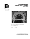
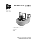
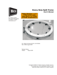
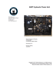
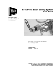
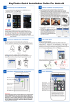
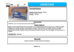
Guillotine Pipe Saw—Autofeed Supplement
Set-Up and Operation
Supplemental Instructions
Guillotine Pipe Saw
Autofeed System
NOTE: This supplement replaces the instructions on
pages 16-17 of the Guillotine Pipe Saw manual (part no.
03-MAN-01, Revision 3).
The Guillotine autofeed is a hydraulic system that automatically operates the feed drive from the saw’s cutting motion
drive. The autofeed hydraulic system is self-contained and
is separate from the saw’s hydraulic power source.
In This Chapter
AUTOFEED SYSTEM
COMPONENTS
AUTOFEED DRIVE
SPECIFICATIONS
CHARGING THE HYDRAULIC
SYSTEM
OPERATION
The autofeed is driven by a cam wheel on the saw’s rotating
shaft. The cam on the wheel strikes a feed plunger on the
autofeed system, driving a hydraulic cylinder that rotates
the saw’s feed screw. Figure 1 is a photo of the system. The
components of the autofeed system are illustrated in
Figure 2.
Figure 1. The photograph shows the autofeed system
on the Guillotine saw. (The feed handle has been
removed for autofeed operation.)
E.H. Wachs Company
Part No. 03-SUP-01, Rev. 0-1105
1
Set-Up and Operation
Guillotine Pipe Saw—Autofeed Supplement
If you have the printed version of this supplement, you will
find that the final page is a tabloid-sized sheet showing a
larger version of Figure 2. While following the instructions,
you can fold this sheet out to refer to the drawing.
AUTOFEED SYSTEM COMPONENTS
Figure 2. The drawing illustrates the components of
the Guillotine autofeed system. The numbers are referenced in the instructions in this supplement.
The components
are listed here by
the reference numbers in Figure 2. These numbers also correspond to the
bill of materials in the Guillotine user manual.
1
5
13
14
15
16
17
18
23
24
26
27
29
31
37
59
Hydraulic manifold
Cam
Accumulator nut
Accumulator jam nut
Funnel
Feed plunger
Feed plunger lock nut
Cam wheel
Feed screw
Actuating cylinder
Accumulator
Clutch drive cylinder
Bleeder valve
Needle valve
Pipe plug
Check valve
The Enabling Pin is installed to enable the autofeed.
Remove the pin to operate the feed drive manually.
2
Part No. 03-SUP-01, Rev. 0-1105
E.H. Wachs Company
Guillotine Pipe Saw—Autofeed Supplement
Set-Up and Operation
AUTOFEED DRIVE SPECIFICATIONS
One revolution of the feed screw moves the saw blade down
0.111 inch. The autofeed system feed rate is factory set so
that 34 saw cycles are required for one rotation of the feed
screw. Thus, the saw blade advances approximately 0.003
inch (3 one-thousands) per saw cycle.
Adjusting the Feed Rate
1. Loosen the feed plunger lock nut (reference 17
below).
2. The feed plunger (reference 16) is threaded into the
cylinder rod. Adjust the feed rate by turning the feed
plunger:
•
•
To INCREASE the feed rate, turn the plunger outward
TOWARD the cam wheel.
To DECREASE the feed rate, turn the plunger inward
AWAY from the cam wheel.
3. Tighten the feed plunger lock nut (reference 17).
CHARGING THE HYDRAULIC SYSTEM
Unless otherwise noted, all reference numbers refer to the
drawing in Figure 2 (also shown on the fold-out drawing in
the printed version of this supplement).
E.H. Wachs Company
Part No. 03-SUP-01, Rev. 0-1105
3
Set-Up and Operation
Guillotine Pipe Saw—Autofeed Supplement
Setting up the Manifold for Charging
1. Remove hydraulic manifold assembly (Ref.1) and
place on a workbench with the feed plunger on top.
2. Remove the actuator lever (Figure 3, Ref. 4), actuator
support (Figure 3, Ref. 2), and the manifold endplate
(Figure 3, Ref. 1) from the hydraulic manifold.
Figure 3. Removable components of the hydraulic
manifold.
3. Remove pipe plug (Ref. 37) using a 3/16” Allen
wrench.
4. Install the funnel/needle valve assembly (Ref. 15 &
31) as shown in Figure 4. Open the needle valve (Ref.
31).
Figure 4. Insert the funnel with the needle valve into
the manifold.
5. Fill the funnel with Mobil DTE-24 hydraulic fluid or
equivalent. Let the oil stand a few minutes until air
bubbles have dissipated.
4
Part No. 03-SUP-01, Rev. 0-1105
E.H. Wachs Company
Guillotine Pipe Saw—Autofeed Supplement
Filling and Purging the Hydraulic System
1. Loosen the accumulator jam nut (Ref. 14).
2. Screw the accumulator nut (Ref. 13) IN and then OUT
again. Looking into the funnel, watch for air bubbles
in the hydraulic fluid as you screw the accumulator
nut IN. Repeat this operation until no air bubbles are
visible for at least two cycles. Leave the accumulator
nut in the OUT position.
Set-Up and Operation
Make sure that the
needle valve (Ref.
31) is OPEN, and
the bleeder valve (Ref. 29) is
CLOSED before starting this
procedure.
3. Close the needle valve (Ref. 31).
4. Screw the accumulator nut (Ref. 13) IN until the feed
plunger of the actuating cylinder (Ref. 24) is forced
out.
5. Open the bleeder valve (Ref. 29).
6. Press in the feed plunger (Ref. 24). Just before the cyl-
Make sure that
both the needle
valve (Ref. 31) and
bleeder valve (Ref. 29) are
CLOSED before starting step
4.
inder rod bottoms out, close the bleeder valve.
7. Open the needle valve (Ref. 31). Screw the accumulator nut OUT to refill the accumulator. Close the needle
valve.
8. Repeat steps 4-7 several times to ensure that all the air
is expelled from the actuating cylinder. Finish with the
accumulator nut screwed OUT, and the feed plunger
pressed all the way in.
9. Using a clamp or wire, fix the feed plunger in place so
that it remains pushed in.
10. Screw the accumulator nut (Ref. 13) IN until the rod
of the clutch drive cylinder (Ref. 27) is fully extended.
11. Open the bleeder valve (Ref. 29).
12. Depress and hold in the rod of the clutch drive cylin-
der (Ref. 27). Just before the cylinder rod bottoms out,
close the bleeder valve.
13. Open the needle valve (Ref. 31). Screw the accumula-
Make sure that
both the needle
valve (Ref. 31) and
bleeder valve (Ref. 29) are
CLOSED before starting step
10.
The clutch drive
cylinder is spring
loaded. The spring
will assist you in bleeding this
cylinder.
tor nut OUT to refill the accumulator. Close the needle
valve.
14. Repeat steps 10-13 several times to ensure that all the
air is expelled from the clutch drive cylinder. Finish
E.H. Wachs Company
Part No. 03-SUP-01, Rev. 0-1105
5
Set-Up and Operation
Guillotine Pipe Saw—Autofeed Supplement
with the accumulator nut screwed OUT, and the clutch
drive cylinder rod pressed all the way in.
15. Using a clamp or wire, fix the clutch drive cylinder
rod in place so that it remains pushed in.
16. Open the bleeder valve (Ref. 29).
This step will prevent air from going
back into the system, which is increasingly
important as you continue the
charging procedure.
17. Screw the accumulator nut (Ref. 13) all the way IN to
force hydraulic fluid past the check valve (Ref. 59)
and into the system. Just before the accumulator nut
stops, close the bleeder valve (Ref. 29).
18. With the bleeder valve (Ref. 29) closed, open the needle valve (Ref. 31) and screw the accumulator nut
(Ref. 13) OUT.
19. Close the needle valve (Ref. 31) and open the bleeder
valve (Ref. 29).
20. Screw the accumulator nut (Ref. 13) IN.
21. Repeat steps 18-20 until hydraulic fluid is forced out
of the bleeder valve (Ref. 29) and no air is expelled.
22. Close the bleeder valve (Ref. 29).
23. Open the needle valve and screw the accumulator nut
out to refill the accumulator (Ref. 26). Close the needle valve.
24. Remove the clamps/wires holding the feed plunger
and the clutch drive rod.
Make sure that
both the needle
valve (Ref. 31) and
bleeder valve (Ref. 29) are
CLOSED before performing
step 25.
25. Screw the accumulator nut (Ref. 13) IN until the rod
of the actuating cylinder (Ref. 24) and the clutch drive
rod are extended once more.
Checking the Charging Procedure
The charging procedure is complete only after the following
requirements are met.
•
•
6
There must not be any air visible while bleeding the system.
Screw the accumulator nut (Ref. 13) in until the rod of
the clutch cylinder (Ref. 27) moves approximately 1/8”.
Now depress the rod of the actuating cylinder (Ref. 24).
Part No. 03-SUP-01, Rev. 0-1105
E.H. Wachs Company
Guillotine Pipe Saw—Autofeed Supplement
Set-Up and Operation
The rod of the clutch cylinder (Ref. 27) should instantly
be extended.
If either of the above requirements is not met, the system
will not perform correctly. Repeat steps 4-25 in the previous
section until these requirements are met.
Reassembling the Autofeed System
After the system is charged, reassemble it using the following procedure.
1. Lightly tighten the bleeder valve nut (Ref. 29) and
close the needle valve (Ref. 31).
2. Remove the funnel/needle valve assembly (Ref. 15 &
31) and replace the pipe plug (Ref. 37).
3. Re-tighten the accumulator jam nut (Ref. 14).
4. Reinstall the actuator lever (Figure 5, Ref. 4), actuator
support (Figure 5, Ref. 2), and the manifold endplate
(Figure 5, Ref. 1) to the hydraulic manifold.
Figure 5. Removable components of the hydraulic
manifold.
5. Reattach the hydraulic manifold. The system is now
ready for operation.
OPERATION
1. Set up the saw according to the instructions in the
user’s manual.
2. Make sure the feed drive is all the way at the top
(starting) position.
E.H. Wachs Company
Part No. 03-SUP-01, Rev. 0-1105
7
Set-Up and Operation
Guillotine Pipe Saw—Autofeed Supplement
3. To enable autofeed, insert the Enabling Pin, as shown
in Figure 6. The feed drive will advance automatically
while the saw is operating.
Figure 6. Insert the Enabling Pin to activate autofeed.
Remove the pin to operate the feed drive manually,
and to turn the drive back to the top (starting) position.
If you need to
reverse the feed
drive for any reason, stop the saw and
remove the enabling pin, then
operate the drive manually.
4. When the cut is complete, stop the saw and remove
8
Part No. 03-SUP-01, Rev. 0-1105
the enabling pin. Use the handle to manually reverse
the feed drive.
E.H. Wachs Company