1
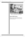
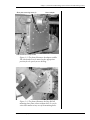
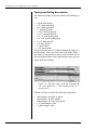
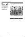
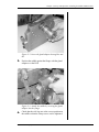
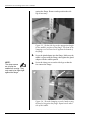
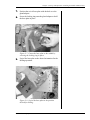
Lock-Down Screw Drilling System
User’s Manual
E.H. Wachs Company
600 Knightsbridge Parkway
Lincolnshire, IL 60069
www.wachsco.com
E.H. Wachs Company Part No. 06-020-MAN
Rev. 0-0407, April 2007
Revision History:
Original
April 2007
Copyright © 2007 E.H. Wachs Company. All rights reserved.
This manual may not be reproduced in whole or in part
without the written consent of E.H. Wachs Company.
Lock-Down Screw Drilling System User’s Manual
Part No. 06-020-MAN, Rev. 0-0407
E.H. Wachs Company
Table of Contents
Table of Contents
Chapter 1: About the LDS Drilling System . . . . . . . . . . . . . . . . . . . . . . . . . . . . . . . . . . . . . . . . 1
Purpose of This Manual . . . . . . . . . . . . . . . . . . . . . . . . . . . . . . . . . . . . . . . . . . . . . . . . . . . . . . . . . 1
How to Use The Manual . . . . . . . . . . . . . . . . . . . . . . . . . . . . . . . . . . . . . . . . . . . . . . . . . . . . . . . . . 1
Symbols and Warnings . . . . . . . . . . . . . . . . . . . . . . . . . . . . . . . . . . . . . . . . . . . . . . . . . . . . . . . . . . 2
Manual Updates and Revision Tracking. . . . . . . . . . . . . . . . . . . . . . . . . . . . . . . . . . . . . . . . . . . . . 2
About the LDS Drilling System . . . . . . . . . . . . . . . . . . . . . . . . . . . . . . . . . . . . . . . . . . . . . . . . . . . 3
Drill . . . . . . . . . . . . . . . . . . . . . . . . . . . . . . . . . . . . . . . . . . . . . . . . . . . . . . . . . . . . . . . . . . . . . . 3
Air Chuck . . . . . . . . . . . . . . . . . . . . . . . . . . . . . . . . . . . . . . . . . . . . . . . . . . . . . . . . . . . . . . . . . 3
Adapter Saddle and Base . . . . . . . . . . . . . . . . . . . . . . . . . . . . . . . . . . . . . . . . . . . . . . . . . . . . . 4
Tooling and Drilling Accessories . . . . . . . . . . . . . . . . . . . . . . . . . . . . . . . . . . . . . . . . . . . . . . . 6
Chapter 2: Safety . . . . . . . . . . . . . . . . . . . . . . . . . . . . . . . . . . . . . . . . . . . . . . . . . . . . . . . . . . . . . 7
Operator Safety . . . . . . . . . . . . . . . . . . . . . . . . . . . . . . . . . . . . . . . . . . . . . . . . . . . . . . . . . . . . . . . . 7
Safety Symbols . . . . . . . . . . . . . . . . . . . . . . . . . . . . . . . . . . . . . . . . . . . . . . . . . . . . . . . . . . . . . 8
Protective Equipment Requirements . . . . . . . . . . . . . . . . . . . . . . . . . . . . . . . . . . . . . . . . . . . . 9
Safety Labels. . . . . . . . . . . . . . . . . . . . . . . . . . . . . . . . . . . . . . . . . . . . . . . . . . . . . . . . . . . . . . . . . . 9
Machine Safety . . . . . . . . . . . . . . . . . . . . . . . . . . . . . . . . . . . . . . . . . . . . . . . . . . . . . . . . . . . . . . . 10
Chapter 3: Set-Up and Operation . . . . . . . . . . . . . . . . . . . . . . . . . . . . . . . . . . . . . . . . . . . . . . . 11
Preparing the Screw for Drilling. . . . . . . . . . . . . . . . . . . . . . . . . . . . . . . . . . . . . . . . . . . . . . . . . . 11
Installing the Saddle and Base Plate . . . . . . . . . . . . . . . . . . . . . . . . . . . . . . . . . . . . . . . . . . . . . . . 12
Assembling and Mounting the Drill . . . . . . . . . . . . . . . . . . . . . . . . . . . . . . . . . . . . . . . . . . . . . . . 17
Drilling out the LDS . . . . . . . . . . . . . . . . . . . . . . . . . . . . . . . . . . . . . . . . . . . . . . . . . . . . . . . . . . . 20
Drilling a Larger I.D. . . . . . . . . . . . . . . . . . . . . . . . . . . . . . . . . . . . . . . . . . . . . . . . . . . . . . . . 23
Chapter 4: Routine Maintenance . . . . . . . . . . . . . . . . . . . . . . . . . . . . . . . . . . . . . . . . . . . . . . . 25
Lubrication . . . . . . . . . . . . . . . . . . . . . . . . . . . . . . . . . . . . . . . . . . . . . . . . . . . . . . . . . . . . . . . . . . 25
Tooling Maintenance . . . . . . . . . . . . . . . . . . . . . . . . . . . . . . . . . . . . . . . . . . . . . . . . . . . . . . . . . . 25
Chapter 5: Parts Lists and Ordering Information . . . . . . . . . . . . . . . . . . . . . . . . . . . . . . . . . 27
Drawings and Parts Lists . . . . . . . . . . . . . . . . . . . . . . . . . . . . . . . . . . . . . . . . . . . . . . . . . . . . . . . 28
Tooling Parts List . . . . . . . . . . . . . . . . . . . . . . . . . . . . . . . . . . . . . . . . . . . . . . . . . . . . . . . . . . 32
Ordering Information . . . . . . . . . . . . . . . . . . . . . . . . . . . . . . . . . . . . . . . . . . . . . . . . . . . . . . . . . . 32
Ordering Replacement Parts . . . . . . . . . . . . . . . . . . . . . . . . . . . . . . . . . . . . . . . . . . . . . . . . . . 32
Repair Information . . . . . . . . . . . . . . . . . . . . . . . . . . . . . . . . . . . . . . . . . . . . . . . . . . . . . . . . . 32
Warranty Information . . . . . . . . . . . . . . . . . . . . . . . . . . . . . . . . . . . . . . . . . . . . . . . . . . . . . . . 33
Return Goods Address . . . . . . . . . . . . . . . . . . . . . . . . . . . . . . . . . . . . . . . . . . . . . . . . . . . . . . 33
E.H. Wachs Company
Part No. 06-020-MAN, Rev. 0-0407
i
Lock-Down Screw Drilling System User’s Manual
ii
Part No. 06-020-MAN, Rev. 0-0407
E.H. Wachs Company
Chapter 1, About the LDS Drilling System
Chapter 1
About the LDS
Drilling System
In This Chapter
PURPOSE OF THIS MANUAL
PURPOSE OF THIS MANUAL
HOW TO USE THE MANUAL
This manual explains how to operate and maintain the PowR-Drill with adapter for lock-down screw (LDS) removal.
It includes instructions for set-up, operation, and maintenance. It also contains parts lists and diagrams to help you
order replacement parts and perform user-serviceable
repairs.
SYMBOLS AND WARNINGS
MANUAL UPDATES AND
REVISION TRACKING
ABOUT THE LDS DRILLING
SYSTEM
HOW TO USE THE MANUAL
This manual is organized to help you quickly find the information you need. Each chapter describes a specific topic on
using or maintaining the equipment.
Throughout this manual, refer
to this column for warnings,
cautions, and notices with
supplementary information.
Each page is designed with two columns. This large column on the inside of the page contains instructions and
illustrations. Use these instructions to operate and maintain
the equipment.
The narrower column on the outside contains additional
information such as warnings, special notes, and definitions. Refer to it for safety notes and other information.
E.H. Wachs Company
Part No. 06-020-MAN, Rev. 0-0407
1
Lock-Down Screw Drilling System User’s Manual
SYMBOLS AND WARNINGS
The following symbols are used throughout this manual to
indicate special notes and warnings. They appear in the outside column of the page, next to the section they refer to.
Make sure you understand what each symbol means, and
follow all instructions for cautions and warnings.
This is the safety alert symbol. It is used
to alert you to potential personal injury
hazards. Obey all safety messages that
follow this symbol to avoid possible
injury or death.
NOTE
This symbol indicates a user notice.
Notices provide additional information to
supplement the instructions, or tips for
easier operation.
MANUAL UPDATES AND REVISION TRACKING
Current versions of E.H.
Wachs Company manuals
are also available in PDF format. You can request an
electronic copy of this manual
by emailing customer service
at [email protected].
Occasionally, we will update manuals with improved operation or maintenance procedures, or with corrections if necessary. Revised accessory manuals will be available for
customers. When a manual is revised, we will update the
revision history on the title page and at the bottom of the
pages.
You may have factory service or upgrades performed on the
equipment. If this service changes any technical data or
operation and maintenance procedures, we will include a
revised manual when we return the equipment to you.
Remove the old manual from your binder and replace it
with the new one.
2
Part No. 06-020-MAN, Rev. 0-0407
E.H. Wachs Company
Chapter 1, About the LDS Drilling System: About the LDS Drilling System
ABOUT THE LDS DRILLING SYSTEM
The components for drilling out and removing lock-down
screws include a modified E.H. Wachs pneumatic Pow-RDrill, and an adapter saddle and mounting plate to attach
and square the drill to the spool assembly.
Special tooling is also provided for drilling the lock-down
screws.
Drill
Components of the Pow-R-Drill are shown in Figure 1-1.
Air motor
Drill body
Compressed air
connector
Feed knob
Drill bit
Tool chuck
Drill slide
Figure 1-1. The photo illustrates the components of
the Pow-R-Drill.
Air Chuck
A special chuck with a compressed air adapter provides air
flow through the insert holders to clear chips during cutting.
When drilling with one of the insert holders, connect a compressed air source to the chuck.
E.H. Wachs Company
Part No. 06-020-MAN, Rev. 0-0407
3
Lock-Down Screw Drilling System User’s Manual
Figure 1-2. The air chuck has a compressed air
adapter to provide air flow to the insert holders.
Adapter Saddle and Base
Figure 1-3 shows the adapter saddle that mounts to the
spool flange. Figure 1-4 show the base that attaches the
Pow-R-Drill to the saddle.
4
Part No. 06-020-MAN, Rev. 0-0407
E.H. Wachs Company
Chapter 1, About the LDS Drilling System: About the LDS Drilling System
Base plate mounting holes (9)
Gland adapter
Side bracket and clamp screw
Figure 1-3. The photo illustrates the adapter saddle.
The side bracket can be moved to the appropriate
position for the spool you are drilling.
Figure 1-4. The photo illustrates the Pow-R-Drill
mounting base plate (shown without drill). It can be
swiveled to mount to any two of the mounting holes.
E.H. Wachs Company
Part No. 06-020-MAN, Rev. 0-0407
5
Lock-Down Screw Drilling System User’s Manual
Tooling and Drilling Accessories
The following tooling is provided with the LDS drilling system:
• 3 spade drill holders
• 1/2” cobalt spade drill
• 3/4” cobalt spade drill
• 1” cobalt spade drill
• 1-1/16” cobalt spade drill
• 1-9/32” cobalt spade drill
• 3/4” x 8” HSS spotting drill
• 3/4” x 10” cobalt spotting drill
• 1” x 8” HSS end mill
• 3/4” insert holder
• 1” insert holder
• 1-1/4” insert holder.
The insert holders have air channels through the length of
the insert body, with a port in the end of the holder. When
you connect a compressed air source to the air chuck, the air
flow through the holder clears chips during cutting, preventing the drill from binding.
Figure 1-5. The photo shows (from top to bottom) the
3/4” insert holder, the 1” insert holder, and the 3/4”
spotting drill.
Drilling accessories include the following components:
•
•
•
•
•
6
Gland adapter for McEvoy glands
Gland adapter for FMC glands
Gland adapter for Vetco Gray glands
3/4” gland adapter collar
1” gland adapter collar
Part No. 06-020-MAN, Rev. 0-0407
E.H. Wachs Company
Chapter 2, Safety
Chapter 2
Safety
In This Chapter
The E.H. Wachs Company takes great pride in designing
and manufacturing safe, high-quality products. We make
user safety a top priority in the design of all our products.
Read this chapter carefully before operating the Pow-RDrill. It contains important safety instructions and recommendations.
OPERATOR SAFETY
SAFETY LABELS
MACHINE SAFETY
OPERATOR SAFETY
Follow these guidelines for safe operation of the equipment.
•
•
•
•
READ THE OPERATING MANUAL. Make sure
you understand all setup and operating instructions
before you begin.
INSPECT MACHINE AND ACCESSORIES.
Before starting the machine, look for loose bolts or
nuts, leaking lubricant, rusted components, and any
other physical conditions that may affect operation.
Properly maintaining the machine can greatly decrease
the chances for injury.
ALWAYS READ PLACARDS AND LABELS.
Make sure all placards, labels, and stickers are clearly
legible and in good condition. You can purchase
replacement labels from E.H. Wachs Company.
KEEP CLEAR OF MOVING PARTS. Keep hands,
arms, and fingers clear of all rotating or moving parts.
E.H. Wachs Company
Part No. 06-020-MAN, Rev. 0-0407
Look for this symbol throughout the
manual. It indicates
a personal injury
hazard.
7
Lock-Down Screw Drilling System User’s Manual
•
•
Always turn machine off before doing any adjustments
or service.
SECURE LOOSE CLOTHING AND JEWELRY.
Secure or remove loose-fitting clothing and jewelry, and
securely bind long hair, to prevent them from getting
caught in moving parts of the machine.
KEEP WORK AREA CLEAR. Keep all clutter and
nonessential materials out of the work area. Only people
directly involved with the work being performed should
have access to the area.
Safety Symbols
This icon is displayed with any safety alert that indicates a
personal injury hazard.
WARNING
This safety alert indicates a potentially hazardous situation
that, if not avoided, could result in death or serious injury.
CAUTION
This safety alert, with the personal injury hazard symbol,
indicates a potentially hazardous situation that, if not
avoided, could result in minor or moderate injury.
NOTICE
This alert indicates a situation that, if not avoided, will
result in damage to the equipment.
8
Part No. 06-020-MAN, Rev. 0-0407
E.H. Wachs Company
Chapter 2, Safety: Safety Labels
IMPORTANT
This alert indicates a situation that, if not avoided, may
result in damage to the equipment.
Protective Equipment Requirements
WARNING
Always wear impact resistant eye protection while operating or working near
this equipment.
For additional information on eye and face protection, refer
to Federal OSHA regulations, 29 Code of Federal Regulations, Section 1910.133., Eye and Face Protection and
American National Standards Institute, ANSI Z87.1, Occupational and Educational Eye and Face Protection. Z87.1 is
available from the American National Standards Institute,
Inc., 1430 Broadway, New York, NY 10018.
CAUTION
Personal hearing protection is recommended when operating or working near
this tool.
Hearing protectors are required in high noise areas, 85 dBA
or greater. The operation of other tools and equipment in the
area, reflective surfaces, process noises, and resonant structures can increase the noise level in the area. For additional
information on hearing protection, refer to Federal OSHA
regulations, 29 Code of Federal Regulations, Section
1910.95, Occupational Noise Exposure and ANSI S12.6
Hearing Protectors.
SAFETY LABELS
There is no safety labeling on the Pow-R-Drill.
E.H. Wachs Company
Part No. 06-020-MAN, Rev. 0-0407
9
Lock-Down Screw Drilling System User’s Manual
MACHINE SAFETY
To avoid damaging the equipment, follow these usage
guidelines.
•
•
•
•
10
Lubricate the machinery according to the recommendations in Chapter 4.
Before starting the machine, make sure the tooling is
inserted and fastened securely.
Make sure that the saddle and adapter plate are securely
fastened.
Make sure that all pneumatic or hydraulic connections
are secure.
Part No. 06-020-MAN, Rev. 0-0407
E.H. Wachs Company
Chapter 3, Set-Up and Operation
Chapter 3
Set-Up and Operation
In This Chapter
Follow the procedures in this chapter to set up the mounting
adapter and Pow-R-Drill, and to drill out the lock-down
screw.
PREPARING THE SCREW FOR
DRILLING
INSTALLING THE SADDLE AND
BASE PLATE
PREPARING THE SCREW FOR DRILLING
1. Remove the gland nut from the lock-down screw you
ASSEMBLING AND MOUNTING
THE DRILL
DRILLING OUT THE LDS
will be drilling.
2. Using a portaband saw, cut the LDS off as close to the
flange as possible.
Figure 3-1. Cut off the LDS as close as possible.
3. Using a new gland nut or a tap, clean the gland nut
threads in the flange.
E.H. Wachs Company
Part No. 06-020-MAN, Rev. 0-0407
11
Lock-Down Screw Drilling System User’s Manual
NOTE:
There are three
gland adapters
supplied with the machine.
These adapters are designed
to fit glands made by McEvoy
(part no. 06-020-007), FMC
(part no. 06-020-008), and
Vetco Gray (part no. 06-020009). Other sizes can be
manufactured on request.
4. Locate the gland adapter that fits the threaded hole and
make sure you can screw it in around the LDS.
Remove the adapter.
Figure 3-2. Select the gland adapter (left) to match
the hole and thread size of the gland nut (right).
INSTALLING THE SADDLE AND BASE PLATE
1. Apply Anti-Seize to the threads on the gland adapter.
2. Put the gland adapter through the saddle hole.
12
Part No. 06-020-MAN, Rev. 0-0407
E.H. Wachs Company
Chapter 3, Set-Up and Operation: Installing the Saddle and Base Plate
Figure 3-3. Insert the gland adapter through the saddle.
3. Position the saddle against the flange with the gland
adapter over the LDS.
Figure 3-4. Attach the saddle by screwing the gland
adapter into the flange.
4. Check that the side legs are at the correct position on
the saddle so that the clamp screws can be tightened
E.H. Wachs Company
Part No. 06-020-MAN, Rev. 0-0407
13
Lock-Down Screw Drilling System User’s Manual
against the flange. Remove and reposition the side
legs if necessary.
Figure 3-5. Set the side legs to the appropriate height
for the saddle’s position on the flange. The head of the
clamping screw will need to be against the bottom of
the flange.
5. Screw the gland adapter into the flange. Make sure the
saddle is square with the flange, then tighten the gland
adapter with the saddle squared.
NOTE:
The clamp screws
are to keep the
saddle from moving. They
only need to be finger-tight
against the flange.
6. Screw the clamp screws on the side legs so that the
feet contact the flange.
Figure 3-6. Turn the clamping screw by hand to snug
the head of it against the flange. Repeat on the other
side of the saddle.
14
Part No. 06-020-MAN, Rev. 0-0407
E.H. Wachs Company
Chapter 3, Set-Up and Operation: Installing the Saddle and Base Plate
7. Position the swivel base plate with the hole over the
gland adapter.
8. Screw the locking ring onto the gland adapter to hold
the base plate in place.
Figure 3-7. Fasten the base plate to the saddle by
screwing the locking ring in place.
9. Swivel the base plate to the desired orientation for the
drilling operation.
Figure 3-8. Swivel the base plate to the position
desired for drilling.
E.H. Wachs Company
Part No. 06-020-MAN, Rev. 0-0407
15
Lock-Down Screw Drilling System User’s Manual
10. Insert the two hex head screws through the slotted
channels in the base plate and screw them into the
holes in the saddle. Tighten the screws securely.
Figure 3-9. Insert the base mounting bolts into the
threaded holes in the saddle.
11. Screw the nuts on the drill mounting bolts out to the
ends of the bolts. You do not need to remove the nuts.
Figure 3-10. Screw the nuts out to the ends of the drill
mounting bolts.
16
Part No. 06-020-MAN, Rev. 0-0407
E.H. Wachs Company
Chapter 3, Set-Up and Operation: Assembling and Mounting the Drill
ASSEMBLING AND MOUNTING THE DRILL
1. Set the drill body onto the drill slide at the farthest-
back position. The two dowel pins on the bottom of
the drill body will fit into holes in the slide.
Dowel pins
Depending on your
work environment,
you may find it
easier to assemble the drill,
drill slide, and base plate first,
then attach the assembly to
the saddle on the flange.
Figure 3-11. Set the drill on the slide with the dowel
pins in the last pair of alignment holes.
2. Attach the drill to the slide with the six captivated
screws in the drill housing.
Figure 3-12. Fasten the drill to the slide with the six
screws in the drill housing.
E.H. Wachs Company
Part No. 06-020-MAN, Rev. 0-0407
17
Lock-Down Screw Drilling System User’s Manual
3. Mount the drill and slide assembly onto the base plate
by inserting the drill mounting bolts in the base plate
through the holes in the end of the slide.
Figure 3-13. Mount the slide by inserting the mounting bolt nuts through the holes in the base of the slide.
4. Tighten the drill mounting nuts until they are just
snug. You will need to move the base plate when you
are ready to align the drill.
5. Insert the alignment shaft into the chuck on the drill.
Feed the drill forward until the alignment shaft is close
to the gland adapter.
18
Part No. 06-020-MAN, Rev. 0-0407
E.H. Wachs Company
Chapter 3, Set-Up and Operation: Assembling and Mounting the Drill
Figure 3-14. Insert the alignment shaft into the chuck
and snug the set screw.
6. Loosen the mounting bolt nuts so that you can move
the base plate up and down. Manually feed the drill
forward while holding the base plate in position so
that the alignment shaft fits into the gland adapter.
If you are assembling and aligning
the drill before
installing it on the flange, you
can do this alignment step by
using a gland adapter
inserted through the hole in
the base plate.
Figure 3-15. Lift the drill and slide so that the alignment shaft fits into the adapter. Feed the drill forward.
7. With the alignment shaft fed into the gland adapter to
center it, tighten the mounting bolt nuts to secure the
drill slide in position.
8. Retract the drill feed and remove the alignment shaft.
E.H. Wachs Company
Part No. 06-020-MAN, Rev. 0-0407
19
Lock-Down Screw Drilling System User’s Manual
9. Install the air motor on the drill and tighten the screws
holding the motor flange.
Figure 3-16. Install the air motor by putting the
flange over the two screws in the drill housing. Turn
the drill to lock the screws in their slots, and tighten
the screws securely.
DRILLING OUT THE LDS
1. Insert the end mill into the chuck of the drill.
2. Turn on power to the drill. Turn the feed knob to feed
the drill into the LDS. Feed the drill until you have
milled the end of the LDS to a flat, square surface.
3. Retract the drill and turn off the motor. Remove the
end mill.
4. Install the 3/4” centering bit into the chuck.
5. Insert the 3/4” centering collar into the gland adapter.
6. Turn on the motor. Feed the drill forward to make a
centering hole about 1/2 inch deep into the LDS stem.
7. Retract the drill and turn off the motor. Remove the 3/
4” centering bit.
8. Remove the 3/4” centering collar from the gland
adapter.
20
Part No. 06-020-MAN, Rev. 0-0407
E.H. Wachs Company
Chapter 3, Set-Up and Operation: Drilling out the LDS
9. Install the air chuck body into the drill chuck.
Figure 3-17. Install the air chuck into the drill.
10. Install the 3/4” insert holder, with tool inserts
installed, into the air chuck body. Connect the air hose
to the air inlet.
Figure 3-18. Install the 3/4” insert holder into the
chuck.
11. Turn on the motor and the air supply to the air chuck.
Feed the drill in to drill through the LDS with the 3/4”
insert.
E.H. Wachs Company
Part No. 06-020-MAN, Rev. 0-0407
21
Lock-Down Screw Drilling System User’s Manual
12. When you are through the LDS, retract the drill and
turn off the motor. Remove the 3/4” insert from the air
chuck body.
13. If required for the gland size you are drilling, install
the 1” insert holder, with tool inserts installed, into the
air chuck body.
14. Install the 1” centering collar into the gland adapter.
Insert the lockscrew into the adapter to retain the collar.
Figure 3-19. Insert the 1” collar into the gland
adapter (top), then put in the lockscrew to hold the
collar in place (bottom).
15. Turn on the motor and the air supply to the air chuck.
Feed the drill in to drill with the 1” insert.
16. When you are through the LDS, retract the drill and
turn off the motor. Remove the 1” insert from the air
chuck body.
22
Part No. 06-020-MAN, Rev. 0-0407
E.H. Wachs Company
Chapter 3, Set-Up and Operation: Drilling out the LDS
Drilling a Larger I.D.
In some cases it may be necessary to cut a final pass larger
than the I.D. of the gland nut collar. Use the following procedure to drill this larger I.D.
1. Remove the gland nut collar from the gland adapter.
2. With no tooling installed on the 1” insert holder, put
the gland nut collar over the holder.
3. Install the larger inserts for the I.D. you will be drilling.
4. Feed the drill forward through the gland adapter until
you can slide the gland nut collar into the adapter.
5. Secure the collar with the lockscrew.
6. Start the drill and air supply, and feed the drill forward
to drill out the lock-down screw.
7. Reverse feed the drill just far enough to retract it from
the hole.
8. Turn off power to the drill.
9. Remove the gland nut collar and slide it back down
the insert holder.
10. Retract the drill completely and remove the drill
inserts.
11. Remove the gland nut collar from the insert holder.
E.H. Wachs Company
Part No. 06-020-MAN, Rev. 0-0407
23
Lock-Down Screw Drilling System User’s Manual
24
Part No. 06-020-MAN, Rev. 0-0407
E.H. Wachs Company
Chapter 4, Routine Maintenance
Chapter 4
Routine Maintenance
In This Chapter
LUBRICATION
LUBRICATION
TOOLING MAINTENANCE
Clean and grease the drill slide each time you use the
machine.
There is one grease fitting on the drill housing. Apply
grease to the fitting each time you use the Pow-R-Drill.
Use a suitable air motor oil as needed when running the air
motor.
TOOLING MAINTENANCE
Check all tooling for sharpness before and after each use.
Replace any worn inserts with new one.
You can sharpen the end mills and drill bits.
Chapter 5 has parts and tooling lists for ordering replacements.
E.H. Wachs Company
Part No. 06-020-MAN, Rev. 0-0407
25
Lock-Down Screw Drilling System User’s Manual
26
Part No. 06-020-MAN, Rev. 0-0407
E.H. Wachs Company
Chapter 5, Parts Lists and Ordering Information
Chapter 5
Parts Lists and
Ordering Information
In This Chapter
Refer to the exploded view drawings and the parts lists that
accompany them for assembly and parts identification. To
order spare or replacement parts, see the ordering instructions at the end of this chapter.
E.H. Wachs Company
Part No. 06-020-MAN, Rev. 0-0407
DRAWINGS AND PARTS LISTS
ORDERING INFORMATION
27
Lock-Down Screw Drilling System User’s Manual
DRAWINGS AND PARTS LISTS
Figure 5-1. Saddle and base plate assembly.
28
Part No. 06-020-MAN, Rev. 0-0407
E.H. Wachs Company
Chapter 5, Parts Lists and Ordering Information: Drawings and Parts Lists
Figure 5-2. Drill spindle assembly.
E.H. Wachs Company
Part No. 06-020-MAN, Rev. 0-0407
29
Lock-Down Screw Drilling System User’s Manual
30
Part No. 06-020-MAN, Rev. 0-0407
E.H. Wachs Company
Chapter 5, Parts Lists and Ordering Information: Drawings and Parts Lists
Figure 5-3. Drill assembly.
E.H. Wachs Company
Part No. 06-020-MAN, Rev. 0-0407
31
Lock-Down Screw Drilling System User’s Manual
Tooling Parts List
06-020-100
SERIES-Z EXT LENGTH SPADE DRILL HOLDER
06-020-101
1/2" SERIES-Z SPADE DRILL COBALT
06-020-102
SERIES-1 EXT LENGTH SPADE DRILL HOLDER
06-020-103
3/4" SERIES-1 SPADE DRILL COBALT
06-020-104
SERIES-2 EXT LENGTH SPADE DRILL HOLDER
06-020-105
1" SERIES-2 SPADE DRILL COBALT
06-020-106
1-1/16" SERIES-2 SPADE DRILL COBALT
06-020-107
1-9/32" SERIES-2 SPADE DRILL COBALT
06-020-108
3/4" X 8" SPOTTING DRILL, HSS
06-020-109
3/4" X 10" SPOTTING DRILL COBALT
06-020-110
1" X 8" END MILL CENTER CUTTING, HSS
06-020-111
SERIES-Z TORX SCREWS
06-020-112
SERIES-1 TORX SCREWS
06-020-113
SERIES-2 TORX SCREWS
06-020-114
#3 MT X 1-1/4" HOLDER W/THRU COOLANT
06-020-115
#3 MT X 3/4" HOLDER W/THRU COOLANT
06-020-116
#3 MT X 1" HOLDER
ORDERING INFORMATION
To place an order, request service, or get more detailed
information on any E.H. Wachs Company products, call us
at one of the following numbers:
U.S.
800-323-8185
International: 847-537-8800
Ordering Replacement Parts
When ordering parts, refer to the parts lists earlier in this
chapter. Please provide the part description and part number
for all parts you are ordering.
32
Part No. 06-020-MAN, Rev. 0-0407
E.H. Wachs Company
Chapter 5, Parts Lists and Ordering Information: Ordering Information
Repair Information
Please call us for an authorization number before returning
any equipment for repair or factory service. We will advise
you of shipping and handling. When you send the equipment, please include the following information:
• Your name/company name
• Your address
• Your phone number
• A brief description of the problem or the work to be
done.
Before we perform any repair, we will estimate the work
and inform you of the cost and the time required to complete it.
Warranty Information
Enclosed with the manual is a warranty card. Please fill out
the registration card and return to E.H. Wachs Company.
Retain the owner’s registration record and warranty card for
your information.
Return Goods Address
Return equipment for repair to the following address.
E.H. Wachs Company
600 Knightsbridge Parkway
Lincolnshire, Illinois 60069 USA
E.H. Wachs Company
Part No. 06-020-MAN, Rev. 0-0407
33
Lock-Down Screw Drilling System User’s Manual
34
Part No. 06-020-MAN, Rev. 0-0407
E.H. Wachs Company
E.H. Wachs Company
600 Knightsbridge Parkway • Lincolnshire, IL 60069
847-537-8800 • www.wachsco.com