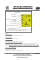
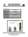
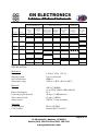
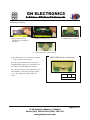
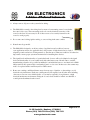
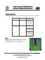
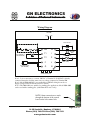
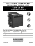
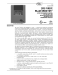
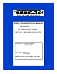
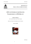
1
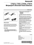
*1(/(&7521,&6
$GLYLVLRQRI3UHIHUUHG,QVWUXPHQWV
Quanta-Flame
Model 5004-890
Primary Control
(Compatible with most Honeywell RA890F & G Series Controls)
USER MANUAL
Note: All rights and privileges to the design of this product including the circuit layout and
software are the exclusive property of GN Electronics, a division of Preferred Instruments.
No part of which can be sold, used, or modified without the expressed written permission
of Preferred Instruments.
Revised: June 1, 2007
Page 1 of 19
6RXWK6W'DQEXU\&7
3KRQH)D[
ZZZJQHOHFWURQLFVFRP
*1(/(&7521,&6
$GLYLVLRQRI3UHIHUUHG,QVWUXPHQWV
DESCRIPTION:
The Quanta-Flame 5004-890 is a state-of-the-art flame safeguard controller designed for single burner
applications. The controller sequences the burner through Purge, Ignition, and Release to Modulate. It
monitors the burner flame and interlocks and safely shuts down the burner in the event of an unsafe
operating condition.
The 5004-890 controller is a direct replacement for most Honeywell RA890
controls.
• No re-wiring or sensor changes required when replacing an RA890 controller.
• Operates with existing UV sensors and flame rods.
The 5004-890 replaces the following models of Honeywell Controls
RA890F-1288
RA890F-1056
RA890G-1120
RA890F-1437
RA890G-1260
RA890G-1062
RA890G-1179
RA890F-1510
RA890F-1031
RA890F-1072
RA890G-1187
RA890G-1047
RA890G-1112
RA890F-1262
Features include:
• Optional plug in diagnostic display.
• Standard relay alarm contact.
• Easy mounting in control panels.
• Pilot Test Mode.
• Selectable Trial for Ignition times. (3, 5, 10, or 15 seconds)
• Selectable interrupted or intermittent pilots
• Selectable recycle or non-recycle modes
Page 2 of 19
6RXWK6W'DQEXU\&7
3KRQH)D[
ZZZJQHOHFWURQLFVFRP
*1(/(&7521,&6
$GLYLVLRQRI3UHIHUUHG,QVWUXPHQWV
ORDERING INFORMATION:
Controllers
Catalog Number
Delivery
5004-890
Stock
5004-890/24V
Stock
5004-890-LG
Stock
5004-890S
Stock?
5004-890A
Stock?
Description
List Price
Discount
List Price
Discount
List Price
Discount
No purge primary control (Accept UV scanner or
flame rod input) 120 VAC supply
No purge primary control (Accept UV scanner or
flame rod input) 24 VDC supply
No purge primary control with history logging
Requires an optional display (5004-216)
No purge primary control for continuous (standing)
pilot applications. Works with flame rod input only.
No purge primary control. Automatically resets on
burner shutdown.
Scanners
Catalog Number
Delivery
5004-01-C
Stock
5004-01
Stock
5002-01
5002-11
Stock
1-2
wks
Description
Ultraviolet scanner for the 5004 series and the 5003
series controls (with cable)
Ultraviolet scanner for the 5004 Series and the 5003
series controls (without cable)
Self-checking UV Scanner (120VAC)
Relay & Flame Amplifier Output
Self-checking IR Scanner (120VAC)
Relay & Flame Amplifier Output
Accessories
Catalog Number
Delivery
5004-270
5004-216
Stock
Stock
5004-216-R
Stock
QD485QA16
Stock
5004-216-RN
Stock
5000-02/10
Stock
5004-890 Tester
Stock
Description
Wiring base for model 5004-890, 5004-795
Plug in display for the 5004 series controls
Remote display package (remote display,
interface & 6 foot cable)
Annunciator with Operator Interface Display
(1/8 DIN panel mount)
16 point analog/digital inputs
Remote display package (remote display, NEMA 4
front membrane, interface, & 6 foot cable)
Scanner cable for 5002-01 and 5002-11 selfchecking scanner.
Tester & demonstrator for 5004-890 & 5004-795
Page 3 of 19
6RXWK6W'DQEXU\&7
3KRQH)D[
ZZZJQHOHFWURQLFVFRP
*1(/(&7521,&6
$GLYLVLRQRI3UHIHUUHG,QVWUXPHQWV
FUNCTIONAL SUMMARY:
Recycle mode- When selected, the control will recycle the burner through purge and startup when the
main burner has shutdown with a flame failure alarm. The recycling of the burner will only occur after the
main burner has been in operation. There is no recycle on pilot flame failure.
Pilot turndown test mode- this mode permits the pilot to ignite and remain burning regardless if
interrupted or intermittent pilot has been selected. The main burner will not be ignited as long as the
control is in this mode. This permits the service technician to adjust and inspect the pilot flame. To enter
this mode hold the reset button down until the limit light begins to flash (10 seconds). To exit the pilot
test mode press the reset button and the control will rest into the normal run mode.
Interrupted pilot- the pilot will ignite and be turned off 10 seconds after the main burner valve is opened
Intermittent (non interrupted pilot)- The pilot will ignite and remain lit for the entire duration of the
main burner run cycle
Pilot verification feature- the ignitor will be de-energized 5 seconds before the main valve is energized
to insure the pilot flame is stable before lighting the main burner
False flame indication- If the control senses a flame out of the proper sequence the sequence will stop
and wait for 30 seconds for the false flame signal to disappear. During this time the Flame Fail light and
the Alarm light will blink on and off. If the signal disappears the lights will cease blinking and the
sequence will continue. If the false flame signal is present for more than 30 seconds the lights will stay on
and stop blinking and the control will go into lockout.
Flame signal analog meter jacks Two test probe inputs are located on the front of the control. By
inserting the meter probes from a high impedance (100k ohm/volt) DC volt meter the control will indicate
the relative flame signal level in the range of 0 to 5 VDC. The positive probe goes into the jack labeled
“Signal 0 to 5VDC”. The negative probe goes into the jack labeled “GND”.
Control Reset: When the control enters a lockout condition the red alarm light will light and begin
blinking. To reset the control press the reset button on the front of the control. The control will not reset
on power interruption. Lockout conditions for the control are:
•
•
•
Flame failure
False flame present for more that 30 seconds
Relay failure and internal fault
Page 4 of 19
6RXWK6W'DQEXU\&7
3KRQH)D[
ZZZJQHOHFWURQLFVFRP
*1(/(&7521,&6
$GLYLVLRQRI3UHIHUUHG,QVWUXPHQWV
LED Indicators
Flame Proven
Limits Made1
Pilot Gas Valves Energized
Main Gas
Valves Energized
Flame Failure
Lockout Condition Occured
Power Applied to Unit
1 Limits
light will blink during internal circuit self-check. Light will remain on when
self-check is complete. Limit light will blink during pilot test mode.
Inputs
Power (Terminal L)
Input that energizes the control electronics and sensor.
Neutral (Terminal N)
Grounded neutral connection to control.
Limits (Terminal LM)
Power and interlocks including the control start switch.
Low Voltage Control Contact (Terminals T1 & T2)
Input is connected to contact switch. This must be a dry contact. No voltage can be applied to these
terminals. If this input is not used then a jumper must be placed between T & T in the base to complete
the circuit. High voltage applied to terminals T1 or T2 will damage control and void the warranty.
Flame Sensor (Terminals F & G)
Sensor inputs:
Flame rod connects to Terminal F
UV sensor connects to F & G. (see wiring schematics)
Page 5 of 19
6RXWK6W'DQEXU\&7
3KRQH)D[
ZZZJQHOHFWURQLFVFRP
*1(/(&7521,&6
$GLYLVLRQRI3UHIHUUHG,QVWUXPHQWV
Outputs
Pilot (Terminal P)
Output to energize the burner pilot valve.
Ignition (Terminal I)
Output to energize the ignition transformer.
Main (Terminal M)
Output to energize the burner main valve.
Alarm (NO, NC, C)
This is a dry contact output, which closes when an alarm condition occurs.
(rated: up to 230VAC, 2 amp. max)
Control Configuration:
Setup Dipswitches: There is a set of 8 dipswitches under the right side cover on the control. Switches 5
through 8 (top 4 switches) are not used on this control
Dipswitches 1 and 2 set the desired trial for pilot ignition time.
This value can be 3, 5,10 or 15 seconds
Dipswitch 3 selects Non-Recycle or Recycle mode.
Recycle mode permits the controller to shut down and start the burner startup sequence again when a
flame failure has occurred during the burner run cycle. In order for this to occur the main burner has to be
up and running before a recycle can occur. A flame failure that happens before that time results in a
lockout regardless if recycle is selected or not.
Dipswitch 4 selects interrupted or intermittent or non-interrupted (continuous) pilot.
An interrupted pilot will ignite during the trial for ignition time and be shut off 10 seconds after the main
gas valve opens to light the main flame.
An intermittent pilot will ignite during the trial for ignition time and will stay lit when the main valve is
open. It will remain on as long as the main burner is on and will shut down at the end of the main burner
cycle.
Page 6 of 19
6RXWK6W'DQEXU\&7
3KRQH)D[
ZZZJQHOHFWURQLFVFRP
*1(/(&7521,&6
$GLYLVLRQRI3UHIHUUHG,QVWUXPHQWV
Dipswitch Setup Table
Dipswitch State
Control Strategy
1
off
2
off
3
---
4
---
3 second PTFI
off
on
---
---
5 second PTFI
on
off
---
---
10 second PTFI
on
on
---
---
15 second PTFI
---
---
off
---
Intermittent pilot
---
---
on
---
Non-intermittent (continuous) pilot
---
---
---
off
Non-recycle operation
---
---
---
on
Recycle operation
Flame failure response time (FFRT): 2.5 to 3.5 seconds (fixed)
Flame Detector Configuration
J2 Terminal strip located under
left side cover of controller.
UV Scanner
Position
Flame Rod
Position
Page 7 of 19
6RXWK6W'DQEXU\&7
3KRQH)D[
ZZZJQHOHFWURQLFVFRP
*1(/(&7521,&6
$GLYLVLRQRI3UHIHUUHG,QVWUXPHQWV
Control Check Cycle
Terminals
Function
Inputs
LM
T1-T2
Internal
Memory
Check
(~6 Secs)
Limit Light
ON Internal
Component
Check
(~ 10 Secs)
Burner Start -up Cycle
Trial for Ignition
(Time set by DIP
Switch selection)
Check for
Pilot Flame
(5 Secs)
Trial for Main
Flame
(10 Secs)
Heat Cycle
Pilot off if
intermittent not
selected
Shutdown
due to flame
fail or limit
trip
Limit
Input
Dry Contact
Input
Outputs
P
Pilot Valve
I
Ignition
M
Main Valve
SPECIFICATIONS:
Mechanical:
Enclosure:
Shipping weight:
Area classification:
Temperature range:
5” H by 5” W by 1 3/4” D
2 lbs. for all models
NEMA 1
-40°F to +140°F (-40°C to +60°C)
Electrical:
Voltage:
Power consumption:
Load ratings (pilot & main):
Total connected load:
Alarm contact:
120 VAC 50/60Hz
12 to 24VDC (Model: 5004-890/24V)
2VA
10 amps (1/4 HP inductive)
15 amps (1800VA)
230VAC, 2 amps maximum
Approvals:
UL Recognized:
CSA Certified:
File No. E233069
Number 204571-1435343
Page 8 of 19
6RXWK6W'DQEXU\&7
3KRQH)D[
ZZZJQHOHFWURQLFVFRP
*1(/(&7521,&6
$GLYLVLRQRI3UHIHUUHG,QVWUXPHQWV
Display Description
The optional 5004-216RN display is a panel mounted display for the 5004 Series Quanta-Flame
Controls. It mount in a control panel through a 1/8 DIN mounting hole and is secured with the
included mounting clips.
During operation the display will indicate each step in the
control sequence. When the main burner is in the run mode the
flame signal level will be indicated in a range of 0 to 5 VDC.
The display constantly refreshes itself with new information
from the control. This refreshing is indicated by the slight periodic blink of the messages.
During the trial for ignition period the display may show a blank line across the top row. This
indicates the presences of an electrical noise field generated by the ignition circuit. This in no
way affects the display or the control. The display will revert to the proper message when the
electrical noise ends.
SPECIFICATIONS:
Mechanical:
Area Classificaton:
Electrical Supply:
Power consumption:
Output:
Environmental:
Enclosure: 1¾” H by 3½” L by 3” D (1/8th DIN)
NEMA type 4 Membrane Front
120 VAC 50/60 Hz
2 VA
Relay reset contact (15 Amps),
communication cable to 5004 control
Temperature rating: -200C to +600C (00F to 1400F).
Page 9 of 19
6RXWK6W'DQEXU\&7
3KRQH)D[
ZZZJQHOHFWURQLFVFRP
*1(/(&7521,&6
$GLYLVLRQRI3UHIHUUHG,QVWUXPHQWV
Installing the display:
1. Insert control connector
carefully line up small pins
with holes
3. Attach cable to controller.
2. Tighten mounting screws.
4. Attach other end of cable to display.
5. Wire 120 VAC power to the three pin terminal
block on the back of the display.
5004-216RN Display Connections
Note: the five pin terminal block on the back of
the 5004-216RN display is not wired when used
in conjunction with the 5004-890 controller.
Note: all power must be removed from the control
when installing or removing the display. Failure
to do so may damage the display and/or the
control.
120V
N
G
Power Connections
Page 10 of 19
6RXWK6W'DQEXU\&7
3KRQH)D[
ZZZJQHOHFWURQLFVFRP
*1(/(&7521,&6
$GLYLVLRQRI3UHIHUUHG,QVWUXPHQWV
Contrast adjustment
Note: The contrast is previously adjusted and set at the factory. It is unlikely that any adjustments will be
required except in unusual lighting situations or in high or low ambient temperature environments.
On the front of the control immediately to the left of the LIMITS light is a contrast adjustment, which can
be used to vary the contrast. To adjust the contrast insert a small instrument screw driver into the hole and
turn the screw clockwise for more contrast or counterclockwise for less contrast.
Once installed the display will show the steps of the control sequence and indicated when an alarm has
occurred. After the start up sequence the display will indicate the flame signal level as a range between 0
to 5VDC
Alarm History (Optional Feature- Display also required)
The Alarm History option allows the user to view the previous alarms occurring in the control, which
caused a lockout. In the case where recycling is selected the control will also indicated the alarm that
occurred to initiate the recycle of the control sequence to relight the burner.
With this option the reset button functions as follows:
Pressing the reset button for less than 6 seconds–The control will reset an alarm lockout condition and
restart the sequence when limits are closed. During this operation the green limit light will also flash
every 2 seconds to indicate the time.
Pressing the reset button more than 6 seconds but less than 12 seconds – The control will enter the “pilot
turndown test mode” as described on page 9. This will be indicated on the display as “Test Mode”
(The green limit light flashes more than 3 times but less than 6) When the button is released the green
limit light will continue to flash to indicate, “Pilot turndown test mode”
Pressing the reset button more than 12 seconds but less than 18 seconds – The control will enter the
“History Log” mode. This will be indicated on the display as “History Log”
(The green limit light flashes more than 6 times but less than 9)
History Log mode – The display will indicate up to 16 previous shutdown/ lockout conditions
with the first condition displayed being the most recent.
Page 11 of 19
6RXWK6W'DQEXU\&7
3KRQH)D[
ZZZJQHOHFWURQLFVFRP
*1(/(&7521,&6
$GLYLVLRQRI3UHIHUUHG,QVWUXPHQWV
Pressing the reset button more than 18 seconds – the history log will be reset and the previous entries will
be deleted. This will be indicated on the display, as “History Reset” for 2 seconds and the control will
reset back to the beginning of the control sequence.
(The green limit light flashes more than 9 times)
Note: Pressing the reset button during a cycle to access the history log will also reset the control
Flame Detection Options:
Ultraviolet Scanner Model 5004-01: The UV sensor detects
light emitted from the flame within the Ultraviolet light
spectrum.
Ultraviolet Self-Check Scanner Model 5002-01: The UV SelfCheck sensor detects light emitted from the flame within the
Ultraviolet light spectrum. This sensor is intended for applications
that continuously operate the burner (24 hours). The self-check
scanner interrupts the UV light from the burner every ten seconds
to verify the proper operation of the sensing element and the
internal components.
Flame rod: The flame rod works on the principle of Flame rectification and senses a small direct current
flowing through the flame between the flame rod and the burner ground.
Installation Notes (read before installing control)
•
All installation, wiring, or service activities must only be performed by knowledgeable and qualified
technicians.
•
All system wiring should be run in accordance with the National Electrical Code and all local code
requirements.
Page 12 of 19
6RXWK6W'DQEXU\&7
3KRQH)D[
ZZZJQHOHFWURQLFVFRP
*1(/(&7521,&6
$GLYLVLRQRI3UHIHUUHG,QVWUXPHQWV
•
Always remove all power to the system before wiring.
•
The 5004-890 is secured to the wiring base by means of ten mounting screws located under
the control side covers. These mounting screws also are the electrical connection of the
control to the base. It is necessary for all of these screws to be securely fastened for the
control to work properly.
•
Do not run control wiring, ignition wiring, or sensor wiring in the same conduit.
•
Neutral must be grounded.
•
The 5004-890 is designed to work in a variety of applications and conditions, however
some applications may not be applicable due to the presence of high electrical noise, lack of
adequate ground connections, floating neutrals or other known or unknown conditions. It is therefore
important to ensure proper system environment before installing these devices.
•
The signal levels and functionality of a particular brand of sensor will not be identical to the signal
levels and functionality of a sensor when used with other burner control brands. Due to variable
manufacturing tolerances it is possible but unlikely for an individual sensor to not function in a 5004890 system but still operate with it own branded control or vise versa. In these cases the scanner may
need to be replaced with a new Honeywell or GNE scanner.
•
Route sensor wiring a sufficient distance away from any type of ignition or other wiring to avoid
electrical noise interference. Each sensor wiring must be run separate from all other wires including
other sensors. In some cases shielded cable or coax may be required for long distances or high
electrical interference environments. Each pair of sensor leads should be in their own shielded or
coaxial pair and terminated at the control.
Page 13 of 19
6RXWK6W'DQEXU\&7
3KRQH)D[
ZZZJQHOHFWURQLFVFRP
*1(/(&7521,&6
$GLYLVLRQRI3UHIHUUHG,QVWUXPHQWV
Wiring Considerations
Depending on the output option used the wiring requirements will vary somewhat.
Output type
Suggested wire
Contact
14 to 16 AWG
0 to 12VDC
Sensor Signal
14 to 16 AWG
Wiring run
considerations
THHN or
equivalent
Nothing specialcan be run with
other wires in
conduit
THHN if wire is
run in separate
conduit
Shielded cable if
multiple wires are
in one conduit
Coax cable if long
distance runs are
required or if high
level of electrical
noise is present
Note
All wiring runs to the field on, or near, hot surfaces
should be rated for 90°C (195°F) or at least 25°C
(50°F) higher than the surface temperature.
5004-270 Wiring Base
Page 14 of 19
6RXWK6W'DQEXU\&7
3KRQH)D[
ZZZJQHOHFWURQLFVFRP
*1(/(&7521,&6
$GLYLVLRQRI3UHIHUUHG,QVWUXPHQWV
Wiring Diagram
120 VAC
(H)
(N)
GAS VALVES
LIMIT SWITCHES
LM
M
T1
DRY CONTACT
(NO VOLTAGE)
IGNITION
XMR
I
PILOT VALVES
SCANNER INPUT
(SEE BELOW)
NO
T2
P
F
L
G
N
NC
(NOT USED)
C
ALARM CONTACTS
Note 1: It is not necessary to connect 120VAC to Terminal L. If 120VAC is already
connected it must be from the same source as voltage connected to Terminal LM
Note 2: Model 5004-890/24V is not applicable to 120VAC wiring shown above.
Supply voltage for this model must be 12 to 24VDC
Note 3: The 5004-890 is not suitable for standing pilot applications. Model 5004-890S
can be used with a standing pilot. (with Flame Rod sensor only)
NOTE: Alarm connection are made
through the bottom of the control
board on the left terminal side
Page 15 of 19
6RXWK6W'DQEXU\&7
3KRQH)D[
ZZZJQHOHFWURQLFVFRP
*1(/(&7521,&6
$GLYLVLRQRI3UHIHUUHG,QVWUXPHQWV
Typical UV Scanner Wiring
Honeywell Scanners (C7027A) connect with the blue lead connects to the F Terminal and the white lead
connects to G terminal.
Note: Route sensor wiring a sufficient distance away from any type of ignition or other wiring to avoid
electrical noise interference. Each sensor wiring must be run separate from all other wires including other
sensors. In some cases shielded cable or coax may be required for long distances or high electrical
interference environments. Each pair of sensor leads should be in their own shielded or coaxial pair and
terminated at the control.
5004-890 Chassis
Honeywell C7027
Ultraviolet Scanner
Blue
LM
M
T1
I
T2
P
F
L
G
N
White
NO
NC
C
GN Electronics Scanners (5004-01) connect with the black lead connects to the F terminal and the white
lead connects to the G terminal.
Note: Route sensor wiring a sufficient distance away from any type of ignition or other wiring to avoid
electrical noise interference. Each sensor wiring must be run separate from all other wires including other
sensors. In some cases shielded cable or coax may be required for long distances or high electrical
interference environments. Each pair of sensor leads should be in their own shielded or coaxial pair and
terminated at the control.
5004-890 Chassis
GN Electronics 5004-01
Ultraviolet Scanner
Black
White
NO
LM
M
T1
I
T2
P
F
L
G
N
NC
C
Page 16 of 19
6RXWK6W'DQEXU\&7
3KRQH)D[
ZZZJQHOHFWURQLFVFRP
*1(/(&7521,&6
$GLYLVLRQRI3UHIHUUHG,QVWUXPHQWV
Wiring For Flame Rod
Flame rod connects to F terminal and a wire from the burner ground connects to the G terminal.
Note: Route sensor wiring a sufficient distance away from any type of ignition or other wiring to avoid
electrical noise interference. Each sensor wiring must be run separate from all other wires including other
sensors. In some cases shielded cable or coax may be required for long distances or high electrical
interference environments. Each pair of sensor leads should be in their own shielded or coaxial pair and
terminated at the control.
5004-890 Chassis
Flame Rod
(rectification)
Blue
LM
M
T1
I
T2
P
F
L
G
N
White
NO
NC
C
Testing the Installation
This section describes the test procedures that must be performed after installation to insure that the 5004890 and the connected sensor is operating properly. These procedures are mandatory.
These tests are to be performed after any installation of the 5004-890 control, regardless if
it is a new installation or a replacement installation for an existing control
Insert the positive probe of a 0-10 VDC, digital voltmeter into the test
point on the front cover of the 5004-890; insert the negative probe to
ground point. Good flame signal strength will read between 2 and 5
VDC; anything below 1 VDC is inadequate. Also, the red flame light
illuminates when a flame signal is indicated.
Page 17 of 19
6RXWK6W'DQEXU\&7
3KRQH)D[
ZZZJQHOHFWURQLFVFRP
*1(/(&7521,&6
$GLYLVLRQRI3UHIHUUHG,QVWUXPHQWV
Minimum Pilot Test
Run the following test procedures to ensure that the sensor will not detect a pilot flame too small to
reliably light the main flame:
1) Manually shut off the fuel supply to the burner, but not to the pilot.
2) Start the system normally.
3) To enter the pilot test mode, press and hold the reset button for ten seconds on the front of the 5004
control.
4) The control will hold the operating sequence at the pilot flame step. Measure signal strength as
described above.
5) Reduce pilot fuel until the flame relay drops out. Increase pilot fuel until the flame signal is greater
than 1 VDC, and flame relay just manages to pull in.
This is the minimum pilot. If you don’t think this flame will be able to safely light the main burner,
realign the sensor so that it requires a larger pilot flame and repeat steps 2 through 5.
6) Push the reset button located in the lower right corner on the front cover to reset the control into the
normal and begin the normal start-up sequence again.
7) When the sequence reaches the main flame trial for ignition, smoothly restore the fuel supply to the
burner. If the main burner does not light within five seconds, immediately shut off the burner supply to
shut down the system.
Re-align the sensor so that it requires a larger pilot flame. Repeat steps 1 through 6 until the main burner
lights off smoothly and reliably.
Pilot Flame Failure Test
1) Manually shut off the fuel supply to the pilot and the main burner.
2) Place system in pilot test mode
3) Start the system normally. The controller should lock out; if it doesn’t, then the controller is detecting a
false flame signal. Find the problem and correct it before resuming normal operation.
Main Flame Failure Test
1) Manually shut off the fuel supply to the main burner but not to the pilot.
2) Start the system normally. This should ignite the pilot and lock out after pilot interruption. If the
system does not lock out, the controller is detecting a false flame signal Find the problem and correct it
before resuming normal operation.
Spark Sighting Test
1) Manually shut off the fuel supply to the pilot and the main burner.
2) Start the system normally.
3) Measure the flame signal.
Page 18 of 19
6RXWK6W'DQEXU\&7
3KRQH)D[
ZZZJQHOHFWURQLFVFRP
*1(/(&7521,&6
$GLYLVLRQRI3UHIHUUHG,QVWUXPHQWV
4) If a flame signal greater than 1 VDC is measured for more than three seconds during the trial for
ignition, then the sensor is picking up a signal from the spark plug.
Note: Periodically check all interlock and limit switches by manually tripping them during burner
operation to make sure they cause the system to shut down.
Warning: Never operate a system that is improperly adjusted or has faulty interlocks or limit
switches. Always replace faulty equipment with new equipment before resuming operation.
Operating a system with defective safety equipment can cause explosions, injuries, and property
damage.
Warranty and Returns
The 5004-890 is warranted for one (1) year from the date of delivery against
manufacturing defects only. GN Electronics standards terms and conditions apply. GN
Electronics’ liability for its products, whether due to breach of warranty, negligence,
strict liability, or otherwise, is limited to the furnishing of replacement parts and GN
Electronics will not be liable for any other injury, loss, damage or expenses, whether
direct or consequential, including but not limited to loss of use, income of, or damage to
material arising in connection with the sale, installation, use of, inability to use or the
repair or replacement of GN Electronics’ products. Defective units should be returned to
G N Electronics. Controls should be well packed in a suitable container encased in
appropriate stuffing.
Units should be returned to G N Electronics. Controls should be well packed
in a suitable container encased in appropriate stuffing.
All items should be shipped prepaid to:
G N Electronics Inc.
A Division of Preferred Instruments
31-35 South Street
Danbury, CT 06810
Page 19 of 19
6RXWK6W'DQEXU\&7
3KRQH)D[
ZZZJQHOHFWURQLFVFRP