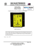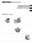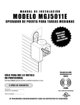
1
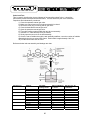
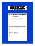
AIR
INCORPORATED
OPERATING AND SERVICE MANUAL
Serial Number: _______
For technical service or repair,
FIRST CALL - INSTALLING CONTRACTOR:
SECOND CALL: Titan Representative
XXX-YYY-ZZZZ
FINAL CALL: Titan Air Inc.
715-597-2050
Please have serial number available when calling
AI R
I N C O R P O R AT E D
24 MONTH WARRANTY
Titan Air, Inc. hereby warrants its products against defects in material and
workmanship for a period of (24) twenty four months from date of shipment.
Start up checklist is due back within (30) thirty days of start-up or 120 days from date
of delivery for 24 month warranty to be effective. After (30) thirty days, and up until (60)
sixty days, a (12) twelve month warranty will be observed. All warranties are null and
void if start up checklist is not received within (60) sixty days from start-up or 120 days
from date of delivery. NO EXCEPTIONS WILL BE MADE.
Titan Air, Inc. reserves the right at Titan Air, Inc.’s option, to replace or repair free of
charge, any part proven by Titan Air, Inc. to be defective. Prompt notification of
defective part must be given to Titan Air, Inc. and defective part must be returned freight
prepaid within (30) thirty days of notification.
WARRANTY INCLUDES ONLY PARTS SUPPLIED BY TITAN AIR, INC.
INCIDENTAL COSTS AND LABOR CHARGES SHALL BE THE RESPONSIBILITY OF
OTHERS. This warranty does not cover fuses, belts, filters or water damaged parts
which are the result of improper storage or installation.
This warranty is void in event the product is improperly installed and/or operated
under conditions other than normal published ratings, improperly maintained, misused or
not in compliance with applicable codes or not in accordance with Titan Air, Inc.’s
operating instructions.
This warranty is void if attempts to correct or repair any alleged defective part or
parts are made by unauthorized personnel without Titan Air, Inc.’s written approval.
In no event shall Titan Air, Inc. be held liable for any damage, incidental or
consequential, arising from the installation, performance or operation of the product.
This warranty supersedes, voids, and/or is in lieu of any other verbal or written
understanding which may not be in total accordance with this expressed warranty.
Warranted parts must be returned to Titan Air, Inc. within 60 days to receive credit.
PURPOSE / APPLICABILITY
This manual is intended to provide installation, operating and service information on
Titan Air’s TA Series H.O.T.™ (High Outlet Temperature) air make-up units. Other types
of equipment including TAP Series H.O.T. ™ units are covered in other manuals.
A packet of reference materials for a specific unit (tracked by its Serial Number) is
generally included with this Operating and Service Manual. The reference materials
include Unit Specifications, Parts Lists, Gas Train and Burner Specifications, Electrical
Schematic, and a Sequence of Operation. A start up checklist is also included in this
packet. Review the reference materials for a specific unit and note any optional
equipment or controls which are not specifically addressed in this manual prior to
attempting start-up or service work.
The information and recommendations contained in this publication are based on
general observation and are not intended to supplant requirements of federal, state or
local codes having jurisdiction. These codes should be reviewed before installation of
equipment. All units must be installed in accordance with national, state or local codes.
It is the responsibility of the purchaser at the time of order, to specify any and all
code or insurance requirements that may dictate the addition of components to the
equipment in order to comply with those requirements.
Only qualified personnel who have experience with the installation and operation of
industrial/commercial direct fired equipment should attempt to service Titan Air
equipment.
1
AI R
I N C O R P O R AT E D
Page
1
WARRANTY
TABLE OF CONTENTS
2
GENERAL INFORMATION
¾ Equipment Arrival
¾ Components
3
AIR FLOW SWITCH OPERATION
7
INSTALLATION
¾ Installation and Field Wiring Overview
8
TYPICAL ASSEMBLY DRAWINGS
11
MAINTENANCE
14
FLAME FAIL DIAGNOSTICS
17
START-UP PREPARATION
19
VALVE LEAK TEST
20
SPECIFIC EQUIPMENT DETAILS
¾ Unit Specification
¾ Unit Drawing
¾ Sequence of Operation
¾ Parts / Legend Sheet
¾ Schematic
¾ Start-Up Procedure
¾ Troubleshooting (optional)
pages not numbered
Note that operating and service manuals are occasionally requested prior to production
of a unit. These manuals will be marked “Pre-Production Release” on the front cover.
The final copy of the operating and service manual for a specific unit will be sent with the
unit. Additional copies of the manual for a specific unit are available.
A detailed unit specification sheet, parts/legend sheet, schematic, sequence of operation
and start-up procedure are provided in the start-up section of each operating and service
manual generated for a specific unit. Selected vendor cut sheets on components will
also be included.
2
AI R
I N C O R P O R AT E D
EQUIPMENT ARRIVAL
When the air make-up unit arrives, be sure to inspect for shipping damage. The
equipment was thoroughly inspected before leaving the factory and the driver signed for
it. Read the bill of lading and verify that all of the items listed are accounted for. Any
damaged or missing items should be reported to the transporter immediately. DO NOT
SEND DAMAGED FREIGHT BACK TO TITAN AIR! All claims must be filed with the
transporter. Be sure to take photographs and get the drivers signature to confirm the
damage. The driver will have a number for you to call to file a claim. Request a written
inspection report from the claims inspector to substantiate any necessary claim. Be sure
to open the unit access doors and inspect for internal damage.
If for some reason you are unable to install the equipment immediately, be sure that
the equipment is protected from the elements. Water damaged parts are not covered by
Titan Air’s warranty. If the equipment is stored for an extended length of time, be sure to
completely check over the unit for any internal damage which may have been caused by
excessive condensation. Also check for any damage caused by rodents, and be sure to
eliminate any dust that may have built up on the components while the unit was in
storage.
CAREFULLY AND THOROUGHLY READ TITAN AIR’S PRODUCT WARRANTY
Each unit is tested at the factory prior to shipping. Because we are not able to
simulate exact field conditions and sometimes actual conditions are different than what
was stated on the order, you may need to make some adjustments in the field. This is
why it is very important that only qualified personnel start-up and service Titan Air
equipment. The start-up checklist (provided in packet with this manual) must be filled
out and returned to Titan Air in order to validate equipment warranty.
For a fee, Titan Air personnel will travel to the job site, supervise start-up and provide
operation and maintenance training for the equipment.
BLOWERS
The typical blower(s) used in Titan Air equipment are AMCA rated industrial type
forward curve D.W.D.I. fans. Backward incline, backward airfoil, and plenum/plug fans
are used occasionally. Models TA-109 through TA-136 utilize a single blower while
models TA-215 and TA-242 utilize twin blowers. All blower wheels are mounted on a
solid, turned, ground and polished shaft. 9” and 12” blowers are supported with
permanently lubricated ball bearings. Larger blowers are supported by relubricatable
pillow block ball bearings.
MOTOR & DRIVE
Rigid base, T-Frame, motors are utilized. The motor is mounted on an adjustable
slide base. Variable pitch motor sheaves are typically provided to allow airflow
adjustment if the motor is no larger than 30 Hp.
3
AI R
I N C O R P O R AT E D
DIRECT FIRED HEATING
Direct fired burners are designed to operate in a fresh flowing airstream. Gas is fed
directly to the burner and the airstream provides the needed oxygen for combustion.
A series of strategically sized and placed holes provide air to the combustion zone.
See Figure 1
The direct fired burner is designed to operate at an air velocity across the burner of
2450 fpm with maximum manifold gas pressure as stated on unit rating plate. Two
speed H.O.T.™ units feature a damper with actuator and controls to maintain proper
velocity across the burner profile as air volume changes. Single speed H.O.T.™ units
have slide plates on either side of the burner to allow manual adjustment of the burner
profile area.
Because of the air pattern, air ports and kinetic energy of the air moving across the
burner, the direct fired burner has the capabilities of a 30:1 turn down ratio. The high fire
rate can be as much as 30 times the low fire rate.
4
AI R
I N C O R P O R AT E D
BURNER OPERATING PRINCIPLES
The direct fired burner is designed to operate in a cabinet of flowing fresh air. Fuel
gas is fed directly to the burner; kinetic energy of the airstream furnishes combustion air.
It will function properly at the design velocity and pressure associated with ventilating
systems.
The burner must be installed to fire with, and parallel to, the air flow. By virtue of
velocity impact and suction generated by the diverging shape of the combustion baffles,
air is induced through the air ports into the combustion zone. The air supply is constant,
even though only that which mixes with the gas takes part in combustion.
When a very small quantity of gas is admitted to the burner, sufficient mixing takes
place in the low fire slot where combustion takes place. Since the low fire zone is
contained within the burner casting it is effectively shielded from uncontrolled air entry.
As the gas supply is increased the flame progresses into the intermediate fire zone
where an additional supply of air is available. At higher or full capacity, mixing occurs at
the larger air ports of the high fire zone augmented by air flowing over the end of the
baffles.
On a reduction of gas supply the reverse sequence takes place, the flame recedes to
a location of lesser air supply until the low fire zone is reached. The burner is suitable
for a turndown range of approximately 30 to 1.
AIR SUPPLY
The supply fan is typically positioned to draw air across the burner. Air flow across
the burner must be substantially straight (laminar) and velocity must be within the proper
range to develop the desired turndown and capacity.
When providing ventilation for an occupied space, the direct fired burner is designed
to operate in an air make-up heater with all air crossing the burner taken directly from
outdoors. The high outlet temperature mode is designed to serve an unoccupied space
and some equipment will re-circulate air across the burner to achieve the high discharge
temperature.
Total pressure rating of the blower includes allowance for the pressure drop through
the primary air handling unit including the burner, together with pressure losses at the
inlet screen, inlet damper, filters, outlet damper if used, plus the external pressure rating
of the system.
BURNERS
Burners are purchased in 6” and 12” straight lengths and 12” tee sections and
are assembled to meet the BTU requirements of each piece of equipment.
According to national safety standards, the following factors could influence safe
operation of a direct fired air make-up unit and must be interlocked to either prevent the
burner from firing or shut it down if unsafe conditions occur.
1. AIR SOURCE – If a damper is used, it must be interlocked to prove it is
open before the blower can start.
2. BLOWER STARTER/VFD INTERLOCK – A contact proving that the blower
starter is energized or VFD is operating must be incorporated to prevent burner
operation when the blower is not operating.
3. AIR FLOW SWITCHES –Monitor the air flow (pressure drop) across the burner.
The switches (one high differential and one low differential) will not allow burner to
operate if air pressure drop across burner is outside of the high and low set points.
5
AI R
I N C O R P O R AT E D
4. HIGH TEMPERATURE LIMIT – A manual reset high temperature limit control
must be utilized to prevent high temperature situations caused by excessive fuel
pressure or lack of air flow.
5. FLAME SAFEGUARD – Monitors the combustion process during ignition and
operation for safe conditions.
6. HIGH GAS PRESSURE SWITCH – Monitors gas pressure to the burner. This
de-energizes the burner in the event gas pressure increases above its set point.
The burner’s design and flexibility, coupled with proper controls, make direct fired air
make-up equipment the safest and most efficient method of tempering outdoor air.
GAS CONTROLS
Titan Air TA Series equipment is constructed to meet A.N.S.I Z83.4/CSA 3.7-1999
standards. Components in the gas delivery manifold on standard equipment include:
two manual shut-off valves, gas pressure regulator, two safety shut-off valves and an
electronic gas modulating valve. The pilot control includes a shutoff valve, gas pressure
regulator and a pilot solenoid.
ELECTRIC/ELECTRONIC CONTROLS
Titan Air H.O.T.™ units typically come standard with the following items: disconnect
switch, starter and overload assembly(s) or variable frequency drive(s), control power
transformer (if a 3 wire system), air proving switches, high temperature limit, electronic
flame safeguard and electronic flame modulation with remote setpoint adjustment. Many
other options including low temperature limit, inlet duct stat, and operating lights are
available.
CABINET
Titan Air TA series equipment comes with either a galvanized finish or a painted
finish. In both cases, the minimum gauge metal used is 18 ga.
6
AI R
I N C O R P O R AT E D
BURNER PROFILE AIR PRESSURE DROP
ANSI standards, Z 83.4/CSA 3.7 M99 & Z 83.18-2000, require manufacturers to
monitor air moving across the burner for both high and low conditions. Titan Air utilizes
air pressure drop across the burner to satisfy this requirement.
Certification testing demonstrated that the burner will function properly between a
low pressure drop of 0.2" w.c. and high pressure drop of 0.95" w.c. The standards also
mandate that the switches cannot be adjustable. This makes air pressure drop across
the burner profile a very important factor at initial start up.
The design burner pressure drop at standard air conditions is 0.60” w.c. and will
change as the temperature of outside air increases or decreases from 70°F. In order for
the burner to operate within the range of the air flow monitoring switch set points, the
pressure drop should be as close to 0.60” w.c. as possible.
Air pressure drop across the burner profile is dependent on OA temperature. When
the burner is off, pressure drop will climb significantly during cold weather. The burner is
always off on initial start-up. Therefore, if the burner profile air pressure drop is above
0.70” w.c. during a warm weather start-up, it may exceed 0.95” w.c. during a cold
weather start-up in northern regions. Such a high air pressure drop would open the high
airflow switch and prevent burner ignition.
The following chart will aid in equipment set up at outside air temperatures different
from 70°F when the unit is operating with the burner off. The chart gives pressure drops,
at various temperatures, equivalent to 0.60” w.c. at 70°F.
Note that two speed H.O.T. units feature controls to maintain pressure drop across
the burner as air volume changes. Either high speed and low speed mechanical
adjustments of damper actuator travel or a dual pressure switch assembly are used to
control burner air pressure drop. Burner profile air pressure drop should be measured
on high speed with the burner profile dampers near the full open position. If the burner
profile dampers open less than 50% on high speed, the unit is probably delivering less
than full rated airflow.
Burner Profile Air Pressure Drop at Various OA Temperatures (Burner Off)
OA
Temp
-40
-35
-30
-25
-20
-15
-10
-5
0
5
Burner
Profile Drop
0.76
0.75
0.74
0.73
0.72
0.71
0.71
0.70
0.69
0.68
OA
Temp
10
15
20
25
30
35
40
45
50
55
Burner
Profile Drop
0.68
0.67
0.66
0.66
0.65
0.64
0.64
0.63
0.62
0.62
7
OA
Temp
60
65
70
75
80
85
90
95
100
105
Burner
Profile Drop
0.61
0.61
0.60
0.59
0.59
0.58
0.58
0.57
0.57
0.56
AI R
I N C O R P O R AT E D
CONTROLS
Control systems can be designed to meet specific requirements. Numerous
temperature controls are available. Since H.O.T. units usually temper outside air to
replace the air exhausted from a paint booth, modulating discharge temperature control
is typical. At least one additional setpoint is usually included for the high outlet
temperature mode.
Titan Air units are typically supplied with a remote control panel. This panel will
include switching for blower & burner operation and temperature setpoint(s). Timers are
often included to automate the bake cycle. Other options common for H.O.T.™ units
include controls to interlock with paint booth lights and compressed air solenoid as well
as control a paint booth exhaust fan. Some units feature operating lights, discharge
temperature display, custom controls or contacts by others to enable blower and/or
burner operation.
Refer to the unit specification sheets, parts list, schematic, sequence of operation
and start-up procedure for a specific unit to determine the control options included.
PRE-INSTALLATION
Inspect the equipment making sure all parts and accessories are on the job site.
Check equipment against order and packing list. If the equipment has been sitting in
storage for some time, inspect it for moisture (from condensation, rain or snow) and/or
dust accumulation. Both can cause damage to electrical and electronic components as
well as bearings and insulation.
INSTALLATION
Care taken during the installation and start-up is vital to the longevity and reliability of
the equipment. Confirm that gas and electric utilities match the rating on the equipment
name plate.
¾ This heater shall be installed in accordance with local codes or, in the absence of
local code, according to ANSI Z223.1.
¾ If the heater is to be installed in an airplane hanger, refer to ANSI/NFPA 409.
¾ If the heater is to be installed in a parking garage, refer to ANSI/NFPA 88A.
¾ If the heater is to be installed in a service garage, refer to ANSI/NFPA 88B.
¾ For installations in Canada, refer to CAN/CGA B149.
¾ Adequate exhaust and/or relief must be provided to prevent over pressurizing the
served space when the heater is operating at its rated capacity.
¾ If in doubt regarding the application of the direct fired heater, contact the sales
representative or the factory.
POSITIONING THE HEATER
Locate the heater exactly level, making certain minimum clearance required by local
codes is maintained between the heater and any combustible materials. See name
plate on unit for minimum recommended clearances.
8
AI R
I N C O R P O R AT E D
CURBING (OUTDOOR MOUNTING)
The use of a full perimeter curb or mounting rails under the heater is recommended.
The only openings in the roof should be for the supply air duct, return air duct (if
required), gas and electrical connections (if applicable). These openings must be sealed
properly after installation. Titan Air ships all curbs unassembled and un-insulated.
Installing contractor supplies gaskets, cant strips, insulation, etc.
GAS PIPING
Gas piping must be sized and installed in accordance with applicable codes. It must
be able to deliver the specified CFH and gas pressure at full flow. Refer to unit
nameplate or unit specification sheets for specified CFH and gas pressure.
Care must be taken with the gas piping to prevent problems at start-up and later
during operation. Before the union between the supply line and the unit is connected,
the supply line should be cleaned out to remove any foreign material (dirt, rust, metal
shavings, etc.).
Refer to unit nameplate to determine the minimum gas supply pressure required to
attain the maximum specified gas.
All suitable gas controls, regulators and valves (equipped with a diaphragm) in this
device are furnished with an ANSI approved vent limiter. If local codes require these
components be vented to the outside, it is the responsibility of the installing contractor.
The heater and its individual shut off valve must be disconnected from the gas
supply piping system during any pressure testing in excess of ½ PSIG.
The heater must be isolated from the gas supply piping system by closing its
individual shut off valve during any pressure testing of the supply system at pressures
equal to or less the ½ PSIG.
During start-up, the technician should perform a gas leak check on all valves and
piping during the heater’s normal operation.
DUCTWORK
Ductwork must be sized and installed in accordance with applicable codes and
standards. A size variation may exist from recommended duct size to unit flange size.
Recommended duct size applies to the size of the duct at the connection to the
equipment. A properly designed duct transition from the blower outlet to a larger duct is
recommended for long ducts or ducts with numerous elbows.
On heaters mounted outdoors, discharge ductwork should be insulated to minimize
condensation during the “off” cycle in cold weather. A fresh air intake hood with bird
screen is required. Discharge duct should be common to both blowers on twin blower
units. Individual ducts for each blower are not recommended.
On a heater mounted indoors with through the roof intake, a “mushroom” type intake
hood is recommended to prevent moisture entrainment. When using “through the wall”
intake duct, the intake louver should have adequate moisture baffling characteristics. All
intake ductwork exposed to the heated space should be insulated.
9
AI R
I N C O R P O R AT E D
SOUND CONTROL
Flexible connectors are recommended on at least one ductwork connection.
Vibration isolators that mount between the unit and support structure are optional and
can be supplied with the equipment for installation by others. Another option is internal
isolation of the blower/motor assembly with internal flexible connections between the
blower housing and the unit structure.
Appropriate insulation on the interior of ductwork significantly reduces sound levels.
DISCHARGE TEMPERATURE SENSOR BULB INSTALLATION & WIRING
The installing contractor may be responsible for field installation of the discharge
temperature sensor. Field installation of the discharge temperature sensor in the
discharge ductwork results in a better measurement of the average supply air
temperature. For paint booth applications, the sensor should typically be located as
close to the booth’s supply air plenum as possible. Utilize shielded cable for field
installed discharge sensor wiring.
FIELD WIRING
Power supply wiring should be routed from a dedicated branch circuit per schematic.
Depending upon how the equipment was ordered, a single point power connection may
be subdivided to individual loads or multiple power supply circuits may be required.
If an intake or discharge damper was ordered as a loose accessory, it will have to be
mounted and the actuator must be wired. The remote panel must be mounted in a
convenient location and wired to the unit. Interlocks between the exhaust, unit and
possibly spray booth will have to be connected by field wiring.
Carefully review the schematic and associated schematic symbol legend. Note that
legend may be on the parts/legend sheet rather than on the schematic.
Many codes require that low voltage wiring be routed in separate conduit from line
voltage wiring. If low voltage wiring is routed with 120 VAC control voltage wiring, it
must be placed in shielded cable(s) with appropriate insulation rating. Even if low
voltage wiring is routed in separate conduit, very low voltage sensor outputs and
actuator control signals should be routed in shielded cable.
NOTE: All field wiring must conform to N.E.C. and/or any state or local codes.
SUPPORT OF ACCESSORIES
Most Titan Air equipment is supplied with loose accessories (i.e. damper, hood,
discharge diffuser or filter section). If an intake hood is supplied by others, the design
shall minimize entry of snow/rain and include an intake screen to meet ANSI standards.
Intake accessories on large equipment may be shipped in two pieces for field assembly.
Two damper actuators may need to field wired on large equipment as well.
It is the responsibility of the installing contractor to support accessory items from a
rigid point or points to ensure solid mounting.
POST INSTALLATION
Caulking is required between all parts prior to assembly and seams must be
re-caulked after assembly. Air make-up units shipped in multiple sections will
include a high quality caulk tape and caulk tubes. Caulk tape is applied between
sections with exterior caulking applied after the unit sections have been joined.
Sealing integrity should be rechecked on a yearly basis.
Water damaged parts are not covered by Titan Air’s warranty.
10
AI R
I N C O R P O R AT E D
11
AI R
I N C O R P O R AT E D
12
AI R
I N C O R P O R AT E D
13
AI R
I N C O R P O R AT E D
GENERAL MAINTENANCE
As with any equipment or machinery, a maintenance program should be
implemented. A well maintained unit will perform efficiently for many years.
Equipment maintenance should include the following:
1. Check filters and clean or replace as needed.
2. Lube bearings.
3. Check belts and belt tension.
4. Check all hardware (bearings, etc.) for tightness.
5. Check settings for all controls.
6. Check duct connections for leaks.
7. Re-caulk seams if needed.
8. Check burner and flame rod - clean if necessary.
9. Perform complete start-up procedure once per year (prior to heating season).
FILTERS
Dirty or clogged filters will restrict air flow which in turn affects the burner operation.
Therefore, it is necessary to check filters on a regular basis. Cleanable filters can be
removed from the filter rack and sprayed with a low pressure water. Always spray these
filters in the opposite direction to air flow and apply new coating to filters when dry.
BURNER
Maintaining the pilot assembly is essential to reliable operation. During pre-heating
season maintenance, the burner should be lit numerous times to confirm reliability. If
ignition system components require servicing, pay attention to the following:
1. Handle porcelain spark rod and flame rod with care. Small cracks lead to
intermittent ignition problems.
2. Midco burners utilize the pilot gas tube as a ground point for the ignition rod.
Keep this grounding point free from scale or other contaminant build-up.
3. Ignition wire routing should remain separated from sheet metal cabinet to
maintain optimal spark strength.
4. Dielectric grease is utilized inside of the ignition and flame sensor connection
boots to limit potential for moisture in the connection.
5. Maintaining low pilot regulator output pressure typically produces reliable ignition.
Excess pilot pressure creates a gas rich region that will not ignite consistently.
6. The pilot solenoid is disabled following main flame ignition. The low fire setting
must be high enough to maintain a proper amplified flame rectification signal.
Check that burner baffles are firmly attached to each other and to burner casting. Do
not use excessive force on screws in casting. Clean baffles with wire brush if needed.
Burner orifices may need to be re-drilled due to rust or other build-up. Burners with
aluminum castings will rarely require orifice cleaning. Use drill bit sizes listed below.
Fuel Type
Natural Gas
Natural Gas
LP Gas
LP Gas
Low Fire Air Ports
Burner Model
Eclipse AH-MA
Midco HMA-2 or 2A
Eclipse AH-MA
Midco HMA-2 or 2A
Midco HMA-2 or 2A
14
Orifice Size
2.4 mm Bit
1/8” Bit
2.0 mm Bit
1/8” Bit
#43 Bit
AI R
I N C O R P O R AT E D
BELT TENSION
Proper sheave alignment and belt tension are critical to belt and bearing service life.
Incorrect belt tension or misalignment of sheaves can cause any of the following:
1. Premature failure of bearings.
2. Premature failure of belts.
3. Reduced air volume.
4. Noise and vibrations.
Each Titan Air unit has as standard equipment an adjustable motor base. To adjust
the belt tension, loosen the motor hold down bolts and adjust the slide base with
adjusting bolt(s) on the end of the base (larger bases will have 2 adjustment bolts).
Loose belts will slip. Excessive belt tension will shorten belt and bearing life. Use a belt
tension tester and associated tables to determine proper tension. Re-tension after the
first day of operation with new belts and periodically thereafter.
Common belt tension gauges will specify a force required to produce a deflection of
1/64” per inch of span. The force required to achieve this deflection is typically in the
range of 3 lbs for A-belts, 5 lbs. for B-belts, and 15 lbs. for 5V belts. See Figure 1 below.
Note that optimal belt tension is the lowest tension at which the belts will not slip
under peak load. Peak load typically occurs at start-up.
SHEAVE ALIGNMENT
With the use of a straight edge, sheave alignment can be checked quickly and
accurately. One of the sheaves will have to be loose on its shaft in order to make
adjustment. Adjust until all 4 points are in contact with the straight edge (see Figure 2).
Repeat on the other side of sheaves and then re-tighten.
If a face width variation exists, measure the difference between each side of the
narrowest sheave and adjust until both sides are an equal distance from the straight
edge.
D eflection 1/64"
per inch of span
Motor Base
Force
Figure 1
S tr aig h t Ed g e
1
2
3
F ig u re 2
15
4
AI R
I N C O R P O R AT E D
BLOWER BEARINGS
Bearings must be checked during each periodic maintenance inspection. Bolts and
set screws should be checked for tightness and the bearings may need lubrication. The
following is intended only as a guide to aid you in setting up your own schedule
LUBRICATION GUIDE FOR BLOWER BEARINGS
Operating conditions
Clean
Dirty
Moisture
Bearing Temp. (°F)
32 - 120
120 - 150
150 - 200
32 - 150
150 - 200
32 - 200
Grease Interval
6 - 10 months
1 - 3 months
1 - 4 weeks
1 - 4 weeks
Daily - 1 week
Daily - 1 week
MOTOR BEARINGS
Motor bearings in a clean environment should be lubricated every 2 to 3 years.
Under more severe conditions of dirt or moisture, lubrication may be required every 6
months to 1 year. Typical motor bearing lubrication procedure follows:
1.
2.
3.
4.
5.
Remove fill and drain plugs.
Clean drain port of hard grease (with wire if necessary).
Add grease (cavity should be no more than ½ full.).
Start motor and let run for 10 minutes.
Wipe off any drained grease and replace fill and drain plugs.
Avoid adding an excessive amount of grease since this a common cause of motor
failure.
BLOWER
Ensure that blower hub is securely fastened to shaft. Inspect blower wheel and
blades for signs of damage or cracks. Clean blades if necessary to maintain proper
balance and performance. Avoid use of excessive grease on blower bearings that can
coat fan blades and attract dirt
16
AI R
I N C O R P O R AT E D
FIREYE MICRO M SERIES LED INDICATING LIGHTS – STANDARD OPERATION
¾ Operating Control - Energized whenever the burner control switch is on and power
is applied to terminal #7 in the flame safeguard.
¾ Interlock - Illuminated solid when power is applied on terminal # 6 in the flame
safeguard to indicate that the air flow switch and other control & limit switches are
closed. This light flashes once per second if the user has selected the fan-only
mode (summer) or if an airflow switch or other safety circuit switch is open.
¾ PTFI - Illuminated only during the pilot trial for ignition period.
¾ Flame - Illuminated when flame signal is detected.
¾ Alarm - LED will flash once per second when an alarm condition is detected.
FIREYE MICRO M SERIES LED INDICATING LIGHTS – ALARM MODE
Symbol Legend
Flashing Light
Lockout Description
Solid Light
OPR CNTL
Line Frequency Noise Detected
Flame Fail – PTFI
Fault Unknown
Amplifier High Count Fail
Flame Fail – MTFI
False Flame – Standby
Interlock Open
Interlock Closed
Chassis Opto
Flame Fail – Auto
Check Chassis
Check Programmer
Amplifier Auto Check Fail
Check Blown Fuse
Check Sensor
17
Light Off
INTRLK
PTFI
FLAME
ALARM
AI R
I N C O R P O R AT E D
Line Frequency Noise Detected - At start up, the MICRO M measures the AC line to
determine if the input is 50 Hz or 60 Hz and set its flag accordingly. As the system is
running, line frequency is constantly monitored. Outside interference causing a
momentary shift in line frequency could be from SCR controls, VFD’s, etc.
Flame Fail - PTFI - No flame signal present at the end of pilot trial for ignition period.
Fault Unknown - A catch all message when, under certian high noise conditions, the
lockout message may become garbled and not translatable into any existing message
Amplifier Count Fail - A message used to detect a failed amplifier module that would
generate an inordinate amount of pulses to micro computer, usually due to a shorted
transistor or oscillating electronic filter
Flame Fail - MTFI - No flame signal present during main burner trial for ignition period.
Flame Fail - Standby - Flame signal present, for a constant 60 seconds, while control is
in standby or off condition
Interlock Open - Interlock safety circuit (terminal #6) has been detected open for longer
than ten minutes during the purge cycle or during main flame period on MEP 562.
Interlock Closed - If selected by dip switches, air flow or interlock switch (terminal #6) is
closed 30 seconds after the start of a cycle or when terminal #7 is closed. Titan Air does
not use this function.
Chassis Opto - Opto coupler located on chassis has been found to be defective. Opto
couplers are checked every 1/2 cycle of the AC main(s) to ensure they are off during the
negative 1/2 cycle.
Flame Fail Auto - If dip switches selected for non-recycle, no flame is detected during
the run cycle or main flame period.
Check Chassis - At beginning of cycle terminal #5 is energized.
Check Programmer - At beginning of cycle terminal #3 is energized or an internal
diagnostics test for the Micro controller has failed.
Check Amplifier - Diagnostic problem with amplifier has been found.
Amplifier Auto Check - The amplifier is checked every 8 seconds by the micro computer
to assure it is responding properly.
Check Blown Fuse - At the end of pilot try for ignition, no flame is detected and no power
is present on terminal #3, indicating the fuse, located on chassis, is blown.
Check Scanner - The UV self check scanner (UV equipped units only) is producing
flame pulses during the shutter closed period due to a malfunctioning shutter or a runaway UV tube
18
AI R
I N C O R P O R AT E D
GENERAL START-UP INFORMATION
Even though Titan Air equipment is tested at the factory, it is not the type of
equipment you can throw the switch and walk away from. A complete start-up
procedure must be performed.
The factory cannot duplicate the conditions the equipment will see in the actual
installation (i.e. gas pressure, static pressure, desired control settings, etc…). For this
reason there are field adjustments that have to be made. Performing a complete startup procedure will help ensure that correct adjustments are made and correct operation is
verified. A step-by-step start-up procedure is provided on subsequent pages. While
working through the start-up procedure, record information on the start-up checklist and
return to Titan Air to validate the equipment warranty. The start-up checklist is provided
on cardstock with Titan Air’s address pre-printed on one side.
Because most component failures occur during start-up, it is very important that the
function of every component be checked out during start-up. It is just as important that
the start-up technician realize the malfunction of a component may be caused by other
factors (i.e. air flow, gas pressure, field wiring, etc…) and should fully investigate a
component malfunction and its cause before replacing the component.
Titan Air checks out all returned components and has found approximately 70% of
returned parts are in full operational condition. This history has proven that a little extra
time invested in troubleshooting will often save the considerable investment in parts,
time, and paperwork associated with replacing components.
SUGGESTED TOOLS AND INSTRUMENTS NEEDED FOR START-UP:
Volt/Ohm Meter
Ammeter
Tachometer
Thermometer
Gas pressure gauge (-10” to 0 to +10” of water column typical scale)
Air differential pressure gauge (-2” to 0 to +2” of water column typical scale)
Standard Hand Tools.
Additional items for Maxitrol Series 14 or 44 temperature controls:
¾ 10,000 Ohm potentiometer
¾ ½ watt, 10,000 Ohm resistor
¾ ½ watt, 2,000 Ohm resistor
Additional items for FX Series temperature controls:
¾ 1,070 Ohm resistor (supplied)
19
AI R
I N C O R P O R AT E D
Valve Leak Test
This is a test for checking the closure tightness of the gas safety shutoff valve. It should be
performed by trained and experienced technicians. This test should be part of the scheduled
inspections and maintenance procedures.
1) Close the upstream manual gas valve.
2) Make sure manual test cock on leak test assembly is closed.
3) Remove the test plug on leaving side of gas valve.
4) Close the downstream manual gas valve.
5) Open the upstream manual gas valve.
6) Through the safety system enable the gas valve momentarily.
7) Immerse a ¼” tube vertically into a jar of water.
8) Slowly open the test cock on the leak assembly.
9) Once the rate of bubbles through the test assembly stabilizes, count the number of bubbles
appearing during the ten second time frame. Each bubble is approximately 0.001 cfh.
10) Do this test for each shut off valve.
Reference below leak test assembly and leakage rate chart.
Pipe Size (in)
Medium
3/8 & 1/2
.64 gas
1.57 LP
.64 gas
1.57 LP
.64 gas
1.57 LP
.64 gas
1.57 LP
.64 gas
1.57 LP
.64 gas
1.57 LP
3/4 & 1
1-1/4 & 1-1/2
2
1-1/2
3
Allowable
Leakage SCCH
294
188
301
192
532
341
578
370
752
481
925
592
20
Max. # of Bubbles
in 10 Sec.
7
4
7
5
13
8
15
9
19
12
24
15
Min. # of sec. for
10 bubbles
13
20.4
12.7
19.9
7.2
11.2
6.6
10.3
5.1
8
4.1
6.5