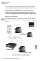
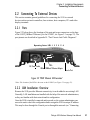
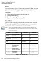
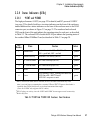
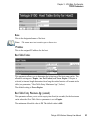
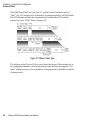
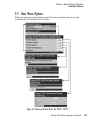
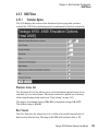
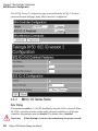
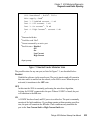
1
9150
Wireless Gateway
User Manual
August 24, 2002
ISO 9001 Certified
Quality Management System
Part No. 80440.G
© Copyright 2002 by Psion Teklogix Inc., Mississauga, Ontario
This document and the information it contains is the property of Psion Teklogix Inc.,
is issued in strict confidence, and is not to be reproduced or copied, in whole or in
part, except for the sole purpose of promoting the sale of Psion Teklogix manufactured goods and services. Furthermore, this document is not to be used as a basis for
design, manufacture, or sub-contract, or in any manner detrimental to the interests of
Psion Teklogix Inc.
All trademarks are the property of their respective holders.
Return-To-Factory Warranty
Psion Teklogix warrants a return-to-factory warranty for a period of 90 days from
shipment or 120 days from shipment where Psion Teklogix installs the equipment.
The warranty on Psion Teklogix manufactured equipment does not extend to any
product that has been tampered with, altered, or repaired by any person other than an
employee of an authorized Psion Teklogix service organization. See Psion Teklogix
terms and conditions of sale for full details.
Service
When requesting service, please provide information concerning the nature of the
failure and the manner in which the equipment was used when the failure occurred.
Type, model, and serial number should also be provided. Before returning any
products to the factory, call the Customer Services Group for a Return
Authorization number.
Support Services
Psion Teklogix provides a complete range of product support services to its
customers. In North America, these services can be accessed through the Psion
Teklogix Helpdesk. The Helpdesk coordinates repairs and training, helps you to
troubleshoot problems over the phone and arranges for technicians or engineers to
come to your site. For contact information and a listing of worldwide offices, please
refer to Appendix A: “Support Services And Worldwide Offices”.
Disclaimer
Every effort has been made to make this material complete, accurate, and up-todate. Psion Teklogix Inc. reserves the right to make changes without notice and shall
not be responsible for any damages, including but not limited to consequential
damages, caused by reliance on the material presented, including but not limited to
typographical errors.
Declaration Of Conformity
Product:
Application of Council
Directives:
Conformity Declared
to Standards:
9150 Wireless Gateway
EMC Directive:89/336/EEC
Low Voltage Directive:73/23/EEC
EN 55022: 1994; Class B; ETS 300 328: 1996
EN 50082-1:1997; ETS 300 683:1997; EN 55024:1998
EN 61000-4-2; ±4kV CD; ±8kV AD
EN 61000-4-3; 3V/m, 80-1000 MHz, 80% AM(1kHz)
EN 61000-4-4; ±1kV Signal lines; ±2kV Power lines
EN 61000-4-5; ±2kV Comm.; ±1kV Differ., ±1kV on I/O lines
EN 61000-4-6; 3VRMS, 150kHz-80MHz, 1kHz 80% AM
EN 61000-4-11; AC Mains Ports
EN 60950: 1992 + A1 + A2 + A3 + A4 + A11
Manufacturer:
PSION TEKLOGIX INC.
2100 Meadowvale Blvd.
Mississauga, Ontario; Canada L5N 7J9
Year of Manufacture:
1998
Manufacturer’s Address
in the European
Community:
PSION TEKLOGIX S.A.
La Duranne
135 Rue Rene Descartes
BP 421000
13591 Aix-En-Provence
Cedex 3; France
Type of Equipment:
Information Technology Equipment
Equipment Class:
Commercial and Light Industrial
Manufacturer:
Hector Perez
Director of Engineering
Psion Teklogix Inc. Ontario
Legal Representative
in Europe:
Dominique Binckly
Vice President International Sales
Psion Teklogix S.A. France
Declaration Of Conformity
Product:
Application of Council
Directives:
Conformity Declared
to Standards:
9150DC Wireless Gateway
EMC Directive:89/336/EEC
Low Voltage Directive:73/23/EEC
EN 55022: 1998; Class B
EN 55024: 1998
EN 61000-4-2; ±4kV CD; ±8kV AD
EN 61000-4-3; 3V/m, 80-1000 MHz, 80% AM (1kHz)
EN 61000-4-4; 0.5kV on DC lines; 0.5kV on I/O
EN 61000-4-5; ±0.5kV on DC lines; ±1kV on I/O lines
EN 61000-4-6; 3Vrms, 0.15-80 MHz; 1kHz 80% AM
Manufacturer:
PSION TEKLOGIX INC.
2100 Meadowvale Blvd.
Mississauga, Ontario; Canada L5N 7J9
Year of Manufacture:
2001
Manufacturer’s Address in
the European Community: PSION TEKLOGIX S.A.
La Duranne
135 Rue Rene Descartes
BP 421000
13591 Aix-En-Provence
Cedex 3; France
Type of Equipment:
Information Technology Equipment
Equipment Class:
Commercial and Light Industrial
Manufacturer:
Hector Perez
Director of Engineering
Psion Teklogix Inc. Ontario
Legal Representative
in Europe:
Dominique Binckly
Vice President International Sales
Psion Teklogix S.A. France
Declaration Of Conformity
Product:
Application of Council
Directives:
Conformity Declared
to Standards:
9100 PowerBaseT
EMC Directive:89/336/EEC
Low Voltage Directive:73/23/EEC
EN 55022: 1998; Class B
EN 55024: 1998
EN 61000-4-2; ±4kV CD; ±8kV AD
EN 61000-4-3; 3V/m, 80-1000 MHz, 80% AM (1kHz)
EN 61000-4-4; 1kV on AC lines; 0.5kV on I/O
EN 61000-4-5; ±2kV Com/±1kV Diff on AC; ±1kV on I/O
EN 61000-4-6; 3Vrms, 0.15-80 MHz; 1kHz 80% AM
EN 61000-4-11; Voltage dips and interruptions on AC
EN 61000-3-2; Harmonic current emissions
EN 61000-3-3; Voltage fluctuation and flicker on AC line
Manufacturer:
PSION TEKLOGIX INC.
2100 Meadowvale Blvd.
Mississauga, Ontario; Canada L5N 7J9
Year of Manufacture:
2001
Manufacturer’s Address in
the European Community: PSION TEKLOGIX S.A.
La Duranne
135 Rue Rene Descartes
BP 421000
13591 Aix-En-Provence
Cedex 3; France
Type of Equipment:
Information Technology Equipment
Equipment Class:
Commercial and Light Industrial
Manufacturer:
Hector Perez
Director of Engineering
Psion Teklogix Inc. Ontario
Legal Representative
in Europe:
Dominique Binckly
Vice President International Sales
Psion Teklogix S.A. France
TABLE
OF CONTENTS
Caution To Users . . . . . . . . . . . . . . . . . . . . . . . . . . . . . . . . . . . vii
Chapter 1: Introduction
1.1
1.2
1.3
1.4
1.5
About This Manual . . . . . . . . . . . . . . . . . . .
Text Conventions . . . . . . . . . . . . . . . . . . . .
About The 9150 . . . . . . . . . . . . . . . . . . . . .
1.3.1 Access Point Functions . . . . . . . . . . .
1.3.2 Base Station Functions . . . . . . . . . . .
1.3.3 Mini-Controller Functions. . . . . . . . . .
Radio Options . . . . . . . . . . . . . . . . . . . . . .
Radio Protocols . . . . . . . . . . . . . . . . . . . . .
1.5.1 IEEE 802.11b Protocol . . . . . . . . . . .
1.5.1.1 Inter-Access Point Protocol (IAPP) .
1.5.1.2 Psion Teklogix’ 802.IQ Protocol . .
1.5.1.3 802.1X Security . . . . . . . . . . .
1.5.2 Adaptive Polling/Contention Protocol . . .
1.5.3 Wlan Protocol . . . . . . . . . . . . . . . .
.
.
.
.
.
.
.
.
.
.
.
.
.
.
.
.
.
.
.
.
.
.
.
.
.
.
.
.
.
.
.
.
.
.
.
.
.
.
.
.
.
.
.
.
.
.
.
.
.
.
.
.
.
.
.
.
.
.
.
.
.
.
.
.
.
.
.
.
.
.
.
.
.
.
.
.
.
.
.
.
.
.
.
.
.
.
.
.
.
.
.
.
.
.
.
.
.
.
.
.
.
.
.
.
.
.
.
.
.
.
.
.
. 3
. 4
. 4
. 6
. 6
. 6
. 7
. 7
. 8
. 9
. 9
. 11
. 13
. 13
.
.
.
.
.
.
.
.
.
.
.
.
.
.
.
.
.
.
.
.
.
.
.
.
.
.
.
.
.
.
.
.
.
.
.
.
.
.
.
.
.
.
.
.
.
.
.
.
.
.
.
.
.
.
.
.
.
.
.
.
.
.
.
.
.
.
.
.
.
.
.
.
.
.
.
.
.
.
.
.
.
.
.
.
.
.
.
.
.
.
.
.
.
.
.
.
. 17
. 17
. 17
. 18
. 18
. 19
. 19
. 19
. 21
. 21
. 21
. 22
Chapter 2: Installation Requirements
2.1
2.2
Choosing The Right Location. . . . . . . .
2.1.1 Environment . . . . . . . . . . .
2.1.1.1 9150 Wireless Gateway .
2.1.1.2 9100 PowerBaseT . . . .
2.1.2 Maintenance . . . . . . . . . . .
2.1.3 Power And Antenna Cables . . .
2.1.3.1 Power . . . . . . . . . .
2.1.3.2 Antennas . . . . . . . .
Connecting To External Devices . . . . . .
2.2.1 Ports . . . . . . . . . . . . . . .
2.2.2 LAN Installation: Overview . . .
2.2.3 LAN Installation: Ethernet . . .
.
.
.
.
.
.
.
.
.
.
.
.
.
.
.
.
.
.
.
.
.
.
.
.
.
.
.
.
.
.
.
.
.
.
.
.
.
.
.
.
.
.
.
.
.
.
.
.
.
.
.
.
.
.
.
.
.
.
.
.
.
.
.
.
.
.
.
.
.
.
.
.
Teklogix 9150 Wireless Gateway User Manual
i
Contents
2.3
2.2.3.1 9150T Wireless Gateway . . . . . . . . . .
2.2.3.2 9150DC Wireless Gateway . . . . . . . . .
2.2.3.3 Ethernet Cabling . . . . . . . . . . . . . . .
2.2.3.4 9100 PowerBaseT Mid-Span Power Supply
2.2.4 Status Indicators (LEDs) . . . . . . . . . . . . . . .
2.2.4.1 9150T and 9150DC . . . . . . . . . . . . .
2.2.5 Connecting A Video Display Terminal . . . . . . .
Changing The Configuration With A Web Browser. . . . . . .
.
.
.
.
.
.
.
.
.
.
.
.
.
.
.
.
.
.
.
.
.
.
.
.
.
.
.
.
.
.
.
.
22
22
23
24
27
27
28
28
.
.
.
.
.
.
.
.
.
.
.
.
.
.
.
.
.
.
.
.
.
.
.
.
.
.
.
.
.
.
.
.
.
.
.
.
.
.
.
.
.
.
.
.
.
.
.
.
.
.
.
.
.
.
.
.
.
.
.
.
.
.
.
.
.
.
.
.
.
.
.
.
.
.
.
.
.
.
.
.
.
.
.
.
.
.
.
.
.
.
.
.
.
.
.
.
.
.
.
.
.
.
.
.
.
.
.
.
.
.
.
.
31
31
33
35
36
36
38
40
41
42
42
43
44
44
44
45
49
50
51
52
54
56
58
58
59
60
61
61
Chapter 3: 9150 Main Configuration
3.1
3.2
3.3
3.4
3.5
3.6
ii
Configuration Main Menu . . . . . . . . . . . . . . . . . . .
Configuring The IP Address . . . . . . . . . . . . . . . . . .
Accessing The Menus . . . . . . . . . . . . . . . . . . . . .
General Configuration Menu Options . . . . . . . . . . . . .
3.4.1 Interfaces . . . . . . . . . . . . . . . . . . . . . .
3.4.1.1 10BaseT Ethernet . . . . . . . . . . . . .
3.4.1.2 100BaseT Ethernet. . . . . . . . . . . . .
3.4.1.3 Slot n: PC Card Radio . . . . . . . . . . .
3.4.2 Users . . . . . . . . . . . . . . . . . . . . . . . .
3.4.3 SNMP . . . . . . . . . . . . . . . . . . . . . . .
3.4.3.1 MapRF . . . . . . . . . . . . . . . . . . .
3.4.3.2 System Parameters. . . . . . . . . . . . .
3.4.3.3 Enable Proxy for non-IP terminals . . . .
3.4.3.4 Proxy throttling . . . . . . . . . . . . . .
3.4.3.5 SNMP Communities and Trap Receivers .
3.4.4 Redundancy . . . . . . . . . . . . . . . . . . . .
3.4.5 SNTP . . . . . . . . . . . . . . . . . . . . . . .
3.4.6 TCP/IP Parameters . . . . . . . . . . . . . . . . .
3.4.6.1 Route Table . . . . . . . . . . . . . . . .
3.4.6.2 Host Table . . . . . . . . . . . . . . . . .
3.4.6.3 Network Interface Configuration Protocol
3.4.6.4 DNS . . . . . . . . . . . . . . . . . . . .
3.4.7 Serial Ports Parameters. . . . . . . . . . . . . . .
3.4.7.1 Console Port . . . . . . . . . . . . . . . .
3.4.7.2 Serial Port . . . . . . . . . . . . . . . . .
Access Point/Base Station/Mini-Controller Menus . . . . . .
Miscellaneous Commands Menu Options . . . . . . . . . . .
3.6.1 System Info. . . . . . . . . . . . . . . . . . . . .
Teklogix 9150 Wireless Gateway User Manual
.
.
.
.
.
.
.
.
.
.
.
.
.
.
.
.
.
.
.
.
.
.
.
.
.
.
.
.
Contents
3.6.2
Reboot Unit . . . . . . . . . . . . . . . . . . . . . . . . . . 62
Chapter 4: Access Point Configuration
4.1
4.2
4.3
4.4
4.5
4.6
4.7
Overview . . . . . . . . . . . . . . . . . . . . . . . . . . . . . . . . . 65
General Configuration Menu: Interfaces . . . . . . . . . . . . . . . . . 66
4.2.1 IEEE 802.11 Direct Sequence Radio Parameters Menu . . . 66
4.2.1.1 802.IQ Version 1 Configuration Menu . . . . . . . . 68
4.2.1.2 802.IQ v1/v2 Common Features Section . . . . . . . 69
4.2.1.3 802.IQ v1 Configuration Section . . . . . . . . . . . 70
4.2.1.4 802.11 Radio Information . . . . . . . . . . . . . . . 72
4.2.1.5 Basic Service Set (BSS) Configuration . . . . . . . . 75
4.2.1.6 Wireless Distribution System (WDS) Configuration . 76
4.2.1.7 802.1X Authenticator Configuration . . . . . . . . . 79
Access Point Configuration Menu Options . . . . . . . . . . . . . . . . 81
MAC Bridge Parameters . . . . . . . . . . . . . . . . . . . . . . . . . 81
4.4.1 General Configuration . . . . . . . . . . . . . . . . . . . . . 83
4.4.1.1 Bridge Spanning Tree Algorithm . . . . . . . . . . . 85
4.4.2 Address Filters: MAC Address . . . . . . . . . . . . . . . . 87
4.4.3 Protocol Filters. . . . . . . . . . . . . . . . . . . . . . . . . 89
4.4.3.1 Ethernet II Filters . . . . . . . . . . . . . . . . . . . 92
4.4.3.2 LLC Filters . . . . . . . . . . . . . . . . . . . . . . 93
4.4.3.3 SNAP Filters . . . . . . . . . . . . . . . . . . . . . 94
4.4.3.4 Storm Detection . . . . . . . . . . . . . . . . . . . . 95
Mobility Configuration . . . . . . . . . . . . . . . . . . . . . . . . . . 96
4.5.1 IAPP Parameters. . . . . . . . . . . . . . . . . . . . . . . . 97
Mobile IP Parameters . . . . . . . . . . . . . . . . . . . . . . . . . . . 98
4.6.1 Mobile IP Configuration. . . . . . . . . . . . . . . . . . . . 99
4.6.1.1 Mobile Agent Parameters . . . . . . . . . . . . . . . 99
4.6.1.2 Mobile Node Parameters . . . . . . . . . . . . . . 100
4.6.1.3 Supported Features . . . . . . . . . . . . . . . . . 101
4.6.1.4 Gratuitous ARP Configuration . . . . . . . . . . . 101
4.6.1.5 Security Configuration . . . . . . . . . . . . . . . 102
802.1X Authenticator Parameters. . . . . . . . . . . . . . . . . . . . 103
4.7.1 802.1X General Parameters . . . . . . . . . . . . . . . . . 103
4.7.2 RADIUS General Parameters . . . . . . . . . . . . . . . . 103
4.7.3 RADIUS Servers . . . . . . . . . . . . . . . . . . . . . . 104
Teklogix 9150 Wireless Gateway User Manual
iii
Contents
Chapter 5: Base Station Configuration
5.1
5.2
5.3
5.4
5.5
Overview. . . . . . . . . . . . . . . . . . . . . . . . . . . .
General Configuration Menu: Interfaces . . . . . . . . . . .
5.2.1 TekLAN Parameters . . . . . . . . . . . . . . . .
5.2.1.1 Radio . . . . . . . . . . . . . . . . . . . .
5.2.1.2 Wireless LAN Parameters . . . . . . . . .
5.2.2 Narrow Band Radio Parameters . . . . . . . . . .
5.2.2.1 General Options . . . . . . . . . . . . . .
5.2.2.2 TRX7370 Radio Card Parameters . . . . .
5.2.2.3 Connectivity Options: Base Station Mode.
5.2.2.4 Connectivity Options: RRM Mode . . . .
Base Station Configuration Menu Options . . . . . . . . . .
5.3.1 Base Stations . . . . . . . . . . . . . . . . . . . .
5.3.2 RRM Groups . . . . . . . . . . . . . . . . . . . .
5.3.2.1 Configure New RRM Group . . . . . . .
5.3.2.2 RRM Group Menu. . . . . . . . . . . . .
5.3.3 Radio Link Features . . . . . . . . . . . . . . . .
Hosts Menu . . . . . . . . . . . . . . . . . . . . . . . . . .
Host Menu Options . . . . . . . . . . . . . . . . . . . . . .
5.5.1 9010 / TCP/IP . . . . . . . . . . . . . . . . . . .
5.5.1.1 General Host Options . . . . . . . . . . .
5.5.1.2 Emulation Options . . . . . . . . . . . . .
5.5.1.3 Protocol Options . . . . . . . . . . . . . .
5.5.1.4 Function Key Mappings . . . . . . . . . .
.
.
.
.
.
.
.
.
.
.
.
.
.
.
.
.
.
.
.
.
.
.
.
.
.
.
.
.
.
.
.
.
.
.
.
.
.
.
.
.
.
.
.
.
.
.
.
.
.
.
.
.
.
.
.
.
.
.
.
.
.
.
.
.
.
.
.
.
.
.
.
.
.
.
.
.
.
.
.
.
.
.
.
.
.
.
.
.
.
.
.
.
. 107
. 110
. 110
. 111
. 113
. 114
. 116
. 116
. 120
. 125
. 126
. 126
. 128
. 128
. 134
. 136
. 140
. 143
. 144
. 144
. 145
. 146
. 146
.
.
.
.
.
.
.
.
.
.
.
.
.
.
.
.
.
.
.
.
.
.
.
.
.
.
.
.
.
.
.
.
.
.
.
.
.
.
.
.
.
.
.
.
. 149
. 151
. 152
. 155
. 157
. 158
. 158
. 158
. 170
. 173
. 174
Chapter 6: Mini-Controller Configuration
6.1
6.2
6.3
6.4
iv
Overview. . . . . . . . . . . . . . . . . . .
Mini-Controller Configuration Menu . . . .
Hosts Menu . . . . . . . . . . . . . . . . .
Host Menu Options . . . . . . . . . . . . .
6.4.1 General Options . . . . . . . . .
6.4.2 9010 Emulations . . . . . . . . .
6.4.3 3274/Telnet . . . . . . . . . . .
6.4.3.1 Emulation Options . . . .
6.4.3.2 Protocol Options . . . . .
6.4.3.3 Function Key Mappings .
6.4.4 5250/Telnet . . . . . . . . . . . .
Teklogix 9150 Wireless Gateway User Manual
.
.
.
.
.
.
.
.
.
.
.
.
.
.
.
.
.
.
.
.
.
.
.
.
.
.
.
.
.
.
.
.
.
.
.
.
.
.
.
.
.
.
.
.
.
.
.
.
.
.
.
.
.
.
.
.
.
.
.
.
.
.
.
.
.
.
.
.
.
.
.
.
.
.
.
.
.
.
.
.
.
.
.
.
.
.
.
.
.
.
.
.
.
.
.
.
.
.
.
Contents
6.5
6.4.4.1 Emulation Options . . . . . . . . . . . . .
6.4.4.2 Protocol Options . . . . . . . . . . . . . .
6.4.4.3 Function Key Mappings. . . . . . . . . . .
6.4.5 ANSI/Telnet . . . . . . . . . . . . . . . . . . . . .
6.4.5.1 Emulation Options . . . . . . . . . . . . .
6.4.5.2 Protocol Options . . . . . . . . . . . . . .
6.4.5.3 Function Key Mappings. . . . . . . . . . .
6.4.6 RF Modem/Telnet . . . . . . . . . . . . . . . . . .
6.4.6.1 Emulation Options . . . . . . . . . . . . .
6.4.6.2 ANSI Telnet Protocol Options (RF Modem)
6.4.6.3 Function Key Mappings. . . . . . . . . . .
802.IQ V2 Features Menu. . . . . . . . . . . . . . . . . . . .
6.5.1 802.IQ Version 2 Configuration . . . . . . . . . . .
6.5.1.1 802.IQ v1/v2 Common Features . . . . . .
6.5.1.2 802.IQ v2 Configuration Sub-Screen . . . .
.
.
.
.
.
.
.
.
.
.
.
.
.
.
.
.
.
.
.
.
.
.
.
.
.
.
.
.
.
.
.
.
.
.
.
.
.
.
.
.
.
.
.
.
.
.
.
.
.
.
.
.
.
.
.
.
.
.
.
.
174
185
188
189
189
192
199
200
200
200
201
201
201
202
203
Chapter 7: 9100 Monitoring/Diagnostics
7.1
7.2
Fault Monitoring . . . . . . . . .
7.1.1 Low Current Detection
7.1.2 High Current Detection
7.1.3 Power Monitoring . . .
Diagnostics and Status Reporting .
.
.
.
.
.
.
.
.
.
.
.
.
.
.
.
.
.
.
.
.
.
.
.
.
.
.
.
.
.
.
.
.
.
.
.
.
.
.
.
.
.
.
.
.
.
.
.
.
.
.
.
.
.
.
.
.
.
.
.
.
.
.
.
.
.
.
.
.
.
.
.
.
.
.
.
.
.
.
.
.
.
.
.
.
.
.
.
.
.
.
.
.
.
.
.
207
207
207
208
208
Specifications For The 9150 Wireless Gateway
8.1.1 Physical Description . . . . . . . . .
8.1.2 9150T Power Requirements . . . . .
8.1.3 9150DC Power Requirements . . . .
8.1.4 Processor And Memory . . . . . . .
8.1.5 Environmental Requirements . . . .
8.1.6 Network Interfaces . . . . . . . . .
8.1.7 PC Card Radios . . . . . . . . . . .
8.1.8 Approvals . . . . . . . . . . . . . .
Specifications For The 9100 PowerBaseT . . .
8.2.1 Physical Description . . . . . . . . .
8.2.2 Power Requirements. . . . . . . . .
8.2.3 Network Interface . . . . . . . . . .
.
.
.
.
.
.
.
.
.
.
.
.
.
.
.
.
.
.
.
.
.
.
.
.
.
.
.
.
.
.
.
.
.
.
.
.
.
.
.
.
.
.
.
.
.
.
.
.
.
.
.
.
.
.
.
.
.
.
.
.
.
.
.
.
.
.
.
.
.
.
.
.
.
.
.
.
.
.
.
.
.
.
.
.
.
.
.
.
.
.
.
.
.
.
.
.
.
.
.
.
.
.
.
.
.
.
.
.
.
.
.
.
.
.
.
.
.
.
.
.
.
.
.
.
.
.
.
.
.
.
.
.
.
.
.
.
.
.
.
.
.
.
.
.
.
.
.
.
.
.
.
.
.
.
.
.
213
213
213
213
213
214
214
214
215
216
216
216
216
Chapter 8: Specifications
8.1
8.2
Teklogix 9150 Wireless Gateway User Manual
v
Contents
8.3
8.2.4 Electrical Safety Approvals . . . . . . . . . . . . . . . . . 216
Lucent/Agere WaveLAN PC Card
Regulatory Information . . . . . . . . . . . . . . . . . . . . . . . . . 217
Appendices
Appendix A: Support Services And Worldwide Offices
A.1 Support Services . . . . . . . . . . . . . . . . . . . . . . . . . . . . .A-1
A.1.1 Canada and U.S.A: Technical Support and Repair Services.A-1
A.1.2 International Support . . . . . . . . . . . . . . . . . . . . .A-1
A.2 Worldwide Offices . . . . . . . . . . . . . . . . . . . . . . . . . . . .A-3
A.3 Worldwide Web . . . . . . . . . . . . . . . . . . . . . . . . . . . . .A-4
Appendix B: Port Pinouts And Cable Diagrams
B.1
B.2
B.3
B.4
Console Port . . . . . . . . . . . . . . . . . . . . . . . .
Serial Cable Descriptions . . . . . . . . . . . . . . . . .
RJ-45 Connector Pinouts (10BaseT/100BaseT Ethernet) .
9100 PowerBaseT Console Port Pinout . . . . . . . . . .
.
.
.
.
.
.
.
.
.
.
.
.
.
.
.
.
.
.
.
.
.
.
.
.
. B-1
. B-2
. B-3
. B-4
.
.
.
.
.
.
.
.
.
.
.
.
.
.
.
.
.
.
.
.
.
.
.
.
.
.
.
.
.
.
. C-1
. C-1
. C-8
C-14
C-15
Appendix C: MAC Bridge Protocol Filters and OUIs
C.1 Ethernet II Types (RFC 1700) . . . . . . .
C.1.1 Listing by Description . . . . .
C.1.2 Listing By Type (Hexadecimal)
C.2 DSAP/SSAP Types . . . . . . . . . . . .
C.3 OUI Values. . . . . . . . . . . . . . . . .
Index
vi
.
.
.
.
.
.
.
.
.
.
.
.
.
.
.
.
.
.
.
.
.
.
.
.
.
.
.
.
.
.
.
.
.
.
.
.
.
.
.
.
. . . . . . . . . . . . . . . . . . . . . . . . . . . . . . . . . . . . . . . . . . . I
Teklogix 9150 Wireless Gateway User Manual
CAUTION TO USERS
This equipment has been tested and found to comply with the limits for a Class B
digital device, pursuant to Part 15 of the FCC rules. These limits are designed
to provide reasonable protection against harmful interference when the equipment
is operated in a commercial environment. This equipment generates, uses and
can radiate radio frequency energy and, if not installed and used in accordance
with the instruction manual, may cause harmful interference to radio communications. Operation of this equipment in a residential area is likely to cause harmful
interference, in which case the user is required to correct the interference at personal
expense. The transmitters supplied are not to be operated within the frequency band
406 - 406.1 MHz.
RF EXPOSURE
Warning:
To satisfy FCC RF exposure requirements for base station
transmitting devices, a separation distance should be maintained
between the antenna of this device and persons during device
operation, as shown in the table below. To ensure compliance,
operations at closer than this distance is not recommended.
Antenna Type
Antenna Gain
Minimum Separation
1/2 Wave
2 dBi
24 dBi
12 dBi
20 cm
15 ft. (4.6 m) high and 10 ft. (3 m) away
15 ft. (4.6 m) high and 10 ft. (3 m) away
CONIFER
Mobile Mark
Changes or modifications not expressly approved by Psion Teklogix Inc. can void
the user’s authority to operate the equipment.
An unshielded plug or cable may cause radiation interference. All peripheral
devices must be used with properly shielded interface cables and external filters as
required. The shield must be connected directly to the chassis of the peripheral
device.
Teklogix 9150 Wireless Gateway User Manual
vii
Safety Summary
IMPORTANT SAFETY INSTRUCTIONS
This safety information is for the protection of both operating and service personnel.
DO NOT OPERATE IN AN EXPLOSIVE ATMOSPHERE
Operating Teklogix equipment where explosive gas is present may result in
an explosion.
DO NOT REMOVE COVERS OR OPEN ENCLOSURES
To avoid injury, the equipment covers and enclosures should only be
removed by qualified service personnel. Do not operate the equipment
without the covers and enclosures properly installed.
DO NOT HOLD ANTENNA
To avoid discomfort due to the local heating effect of radio frequency
energy, do not touch the antenna when a 9150 is transmitting.
CONNECTION TO OUTDOOR ANTENNA
Outdoor antenna to be earthed in accordance with International Standard
EN 50083-1 (1993), “Cabled Distribution Systems for Television and
Sound Signals - Safety Requirements”.
ANSCHLUß AN ANTENNENNANLAGEN
Außenantennennanlagen müssen nach nationalen oder internationalen
Normen (z.B. EN50083-1(1993) geerdet werden.
viii
Teklogix 9150 Wireless Gateway User Manual
1
INTRODUCTION
1.1 About This Manual . . . . . . . . . . . . . . . . . .
1.2 Text Conventions. . . . . . . . . . . . . . . . . . . .
1.3 About The 9150 . . . . . . . . . . . . . . . . . . . .
1.3.1 Access Point Functions . . . . . . . . . .
1.3.2 Base Station Functions . . . . . . . . . . .
1.3.3 Mini-Controller Functions . . . . . . . . .
1.4 Radio Options . . . . . . . . . . . . . . . . . . . . .
1.5 Radio Protocols . . . . . . . . . . . . . . . . . . . .
1.5.1 IEEE 802.11b Protocol. . . . . . . . . . .
1.5.1.1 Inter-Access Point Protocol (IAPP) .
1.5.1.2 Psion Teklogix’ 802.IQ Protocol . .
1.5.1.3 802.1X Security . . . . . . . . . . .
1.5.2 Adaptive Polling/Contention Protocol . . .
1.5.3 Wlan Protocol . . . . . . . . . . . . . . .
.
.
.
.
.
.
.
.
.
.
.
.
.
.
.
.
.
.
.
.
.
.
.
.
.
.
.
.
. . . .3
. . . .4
. . . .4
. . . .6
. . . .6
. . . .6
. . . .7
. . . .7
. . . .8
. . . .9
. . . .9
. . . 11
. . . 13
. . . 13
Teklogix 9150 Wireless Gateway User Manual
1
Chapter 1: Introduction
About This Manual
1.1 About This Manual
This manual contains information about the installation, basic operation, and
configuration of the 9150 Wireless Gateway.
Chapter 1: Introduction
describes the 9150 and the radio protocols it supports.
Chapter 2: Installation Requirements
describes the physical installation of the Teklogix 9150 Wireless Gateway and
9100 PowerBaseT, and how to connect to the 9150 for configuration/diagnostics.
Chapter 3: 9150 Main Configuration
describes the web page options available from the main configuration menus.
Chapter 4: Access Point Configuration
describes the configuration for a 9150 used as an access point device between
wired and wireless networks.
Chapter 5: Base Station Configuration
describes the configuration for a 9150 used as a base station or remote radio
module (RRM) linked to a network controller.
Chapter 6: Mini-Controller Configuration
describes the configuration for a 9150 used as a mini-controller.
Chapter 7: 9100 Monitoring/Diagnostics
describes the fault monitoring, diagnostics and status reporting procedures for
the 9100 PowerBaseT.
Chapter 8: Specifications
outlines the performance specifications for the 9150T, 9150DC and 9100.
Appendix A: Support Services And Worldwide Offices
presents information for technical support, contacts and the Psion Teklogix
worldwide web address.
Appendix B: Port Pinouts And Cable Diagrams
includes pinouts and diagrams of the ports and cables for the 9150.
Appendix C: MAC Bridge Protocol Filters and OUIs
presents tables of values for Ethernet II and DSAP/SSAP types, and OUI.
Teklogix 9150 Wireless Gateway User Manual
3
Chapter 1: Introduction
Text Conventions
1.2 Text Conventions
Note:
Notes highlight additional helpful information.
Important:
These statements provide particularly important instructions or
additional information that is critical to the operation of the
computer and other equipment.
Warning:
These statements provide important information that may prevent
injury, damage to the equipment, or loss of data.
1.3 About The 9150
The 9150 Wireless Gateway is designed to support a wide variety of system configurations. Using the IEEE 802.11b Wireless LAN Standard, the 9150 is capable of
operating as a transparent bridge (access point) between wireless and wired networks.
This allows wireless clients to access the network and also move seamlessly between
the 9150s in the network. The 9150 can also operate as a Teklogix base station, remote
radio module (RRM) or a mini-controller, and become part of a mapRF system.
Because the 9150 provides Ethernet connectivity, it can be added to an existing
LAN. The 9150T provides the high-performance of 100Mb/s Fast Ethernet LANs,
as well as 10Mb/s. The 9150DC edition incorporates most of the features of the
high-performance 9150T, but is DC-powered, eliminating the need for AC wiring.
For detailed information on LAN connectivity, please refer to page 21.
The 9150 supports Type II PCMCIA cards so that multiple radio interfaces are possible. The 9150 also has dual-radio functionality. It can support several combinations of radio types to function as both a mini-controller and base station, access
point and base station, or access point and mini-controller. For details, see “Radio
Options” on page 7.
The 9150 Flash memory holds the boot code, configuration parameters and firmware. The 9150 Configuration program allows various parameter settings to be
changed, added or deleted. The Flash can be reconfigured remotely via the network
using a standard HTML Web Browser such as Netscape or MS Internet Explorer
(for instructions, see Chapter 3: “9150 Main Configuration”).
4
Teklogix 9150 Wireless Gateway User Manual
Chapter 1: Introduction
About The 9150
Figure 1.1 The 9150 Wireless Gateway - Front View
Figure 1.2 The 9150T Wireless Gateway - Bottom View
Figure 1.3 The 9150DC Wireless Gateway - Bottom View
Teklogix 9150 Wireless Gateway User Manual
5
Chapter 1: Introduction
Access Point Functions
1.3.1 Access Point Functions
As an access point connected to a wired network, the 9150 Wireless Gateway forms
a communication link between Teklogix RF terminals or wireless access point
clients and a Teklogix Network Controller or a host computer. It communicates over
an IEEE 802.11b RF data link with terminals, and over a cable with the network
controller or a host computer. The 9150 can be connected to the network through an
Ethernet connection. The diagram in Figure 4.1 on page 65 illustrates a 9150 access
point connection between a Teklogix 9400 Network Controller on Ethernet and
IEEE 802.11 wireless devices.
Two 9150 Wireless Gateways can be used as an 802.11b bridge connecting two separate wired networks. The 9150 can also be used as an 802.11b wireless access point
to extend coverage area or for locations difficult to wire (see Figure 1.4 on page 10).
For information on the 9150 as an access point, see “IEEE 802.11b Protocol” on
page 8 and Chapter 4: “Access Point Configuration”.
1.3.2 Base Station Functions
As a base station or Remote Radio Module (RRM) connected to a wired network,
the 9150 provides a link between the local area network and the wireless network
consisting of Teklogix mobile terminals, and wireless base stations such as the 9150
Wireless Gateway. The 9150 and 9400 Network Controller (or host using a Teklogix
Software Development Kit) communicate using the 9010 proprietary protocol with
TCP/IP over Ethernet connectivity. Wlan protocol enables the wired 9150 to communicate with 9150s without cable attachments (see Figure 5.1 on page 108).
For information on configuring the 9150 as a base station or RRM, see Chapter 5:
“Base Station Configuration”. For Wlan, see “Wlan Protocol” on page 13.
1.3.3 Mini-Controller Functions
The 9150 is equipped with some emulation capabilities, allowing it to act as a minicontroller. When a 9150 is configured as a mini-controller, Teklogix terminals can
emulate an ANSI, 5250 or 3274 terminal through the 9150 rather than through a
9400 Network Controller.
To configure the 9150 as a mini-controller, see Chapter 6: “Mini-Controller Configuration”. For a generalized system diagram, see Figure 6.1 on page 150.
6
Teklogix 9150 Wireless Gateway User Manual
Chapter 1: Introduction
Radio Options
1.4 Radio Options
The 9150 supports Type II PCMCIA cards so that multiple radio interfaces are possible.
There is one internal and one external PC card slot available. The type of PCMCIA
radio card installed in the 9150 is dependent on your wireless network. Currently
supported radios are:
•
TRX7370 Narrow Band DSP (available in either two level or four level
modulation, with bit rates of 4800 b/s and 9600 b/s, or 9600 b/s and 19200
b/s, respectively).
•
TekLAN 902 MHz DS Spread Spectrum (TRX7410).
•
Lucent WaveLAN IEEE 802.11 DSSS 2.4 GHz (TRX7431 - up to 11Mb/s).
The 9150 can support several combinations of radio types, operating on different
channels, to function as both a mini-controller and base station, access point and
base station, or access point and mini-controller. The 902 MHz, 2.4 GHz (802.11
and TekLAN) and Narrow Band radios can be used in any combination, with the
exception of dual TekLAN or dual Narrow Band radios.
Note:
The 9150DC supports dual 802.11 radios, but not Narrow Band or
TekLAN 902 MHz radios. For details on the 9150DC, see page 22.
Important:
The radio in the terminal must match the radio in the 9150 Wireless Gateway. If changing radio types in the 9150, DO NOT “hot
swap” the PC cards: Turn the 9150 off before changing the radio.
1.5 Radio Protocols
RF protocols allow terminals to communicate with a base station by sharing the use
of a radio channel in an efficient way. Teklogix systems use one of three types of RF
protocols: the Teklogix Adaptive Polling/Contention protocol, the Teklogix Wireless
LAN (Wlan) protocol, or the non-proprietary IEEE 802.11b protocol. When used as
a base station, the 9150 uses either the Adaptive Polling/Contention protocol or the
Wlan protocol. These protocols cannot be mixed on a single system. When used as
an access point device, the 9150 employs the IEEE 802.11b protocol. The protocols
are described in the following sections.
Teklogix 9150 Wireless Gateway User Manual
7
Chapter 1: Introduction
IEEE 802.11b Protocol
1.5.1 IEEE 802.11b Protocol
The IEEE 802.11b protocol is an OSI standard for Wireless Local Area Networks
(WLANs). With this standard, any IEEE 802.11b radio can communicate with any
other similarly-equipped device. However, IEEE 802.11b does not provide a standard for a total WLAN system. IEEE 802.11b solely standardizes two communications layers: Physical (PHY) and Medium Access Control (MAC). Three different
PHY layer media are covered: 2.4 GHz Direct Sequence Spread Spectrum radio,
2.4 GHz Frequency Hopping Spread Spectrum radio, and infrared. Each station
in a WLAN system has its own unique MAC address.
Important:
Equipment using one physical medium (e.g. Frequency Hopping
versus Direct Sequence) will not interoperate with equipment
using a different physical medium.
IEEE 802.11b uses 2.4 GHz radios of relatively low power. The range is limited
to no more than a hundred feet or so, depending on the conditions, and is usually
restricted to “line of sight” operation. Therefore, most wireless networks need more
than one coverage area, with terminals moving between the areas. To integrate
those areas, systems using IEEE 802.11b protocol for their wireless networks
require an IEEE 802.11b-equipped bridge device (or access point), such as the
9150 Wireless Gateway.
Using bridging software, the 9150 Wireless Gateway enables communication
between any wireless IEEE 802.11b-equipped stations and LAN stations operating
on Ethernet. The 9150 itself is resident on the LAN and functions as a MAC bridge,
providing transparent integration between the stations on the wireless and
wired networks.
Each terminal is associated with one 9150. A frame from an RF terminal is sent to
the 9150 that the terminal is associated with. The terminal puts a destination MAC
address in the frame, which specifies a hardware address on the wired LAN side.
Because the receiving 9150 is connected to an Ethernet network, it encapsulates the
data in an Ethernet frame, including the destination MAC address specified by the
terminal. The 9150 then sends the frame onto the physical network; the frame is
picked up by whichever device is at the destination hardware address.
When sending frames from the LAN side, the sending device puts the MAC address
of the terminal in the frame header. Whichever 9150 has that terminal associated
with it, takes the frame and passes it over the RF to the terminal. By passing frames
in this way, the 9150 is acting as a MAC bridge.
8
Teklogix 9150 Wireless Gateway User Manual
Chapter 1: Introduction
IEEE 802.11b Protocol
1.5.1.1
Inter-Access Point Protocol (IAPP)
The Inter-Access Point Protocol (IAPP) is an extension to the IEEE 802.11b protocol. IAPP facilitates roaming of mobile stations across different Basic Service Sets
(see Note below) and specifies how access points communicate with each other.
Note:
A Basic Service Set (BSS) is a set of stations (terminals) controlled by a
single coordination function, in this case by the 9150 Wireless Gateway
functioning as an access point within the terminals’ radio coverage area.
In a multiple-9150 system, IAPP informs the other 9150 Wireless Gateways when a
new 9150 becomes active, and enables the awareness of the 9150s of each other.
With IAPP, an IEEE 802.11b system can operate on one or more channels, with
terminals moving between the 9150s. Although each terminal is associated with one
9150, it can re-associate with another 9150 to maintain uninterrupted communications. The newly-associated 9150 will receive the terminal’s data frames and pass
them onto the LAN. Returning frames are no longer accepted by the original 9150,
which has disassociated from that terminal. The returning frames are now accepted
by the newly-associated 9150 and passed over the RF to the terminal.
1.5.1.2
Psion Teklogix’ 802.IQ Protocol
802.IQ is a Psion Teklogix proprietary optimized protocol that enables terminals to
operate on a wireless LAN in a network that supports both TCP/IP and 802.IQ protocol simultaneously. 802.IQ protocol is available in two versions: 802.IQv1 and
802.IQv2. The 9150 can support both versions of the protocol at the same time (terminals must use only one).
802.IQv1 protocol is a wireless LAN routing scheme that provides greater performance in an 802.11b wireless network than is possible with TCP/IP routing. The
9150 bridges the 802.IQv1 wireless and TCP/IP wired networks. A terminal can
communicate with the 9150 access point using either TCP/IP or 802.IQv1 protocol,
which makes possible a system with dual-operability.
802.IQv2 protocol is an enhanced version of the 802.IQv1 protocol that transports
packets over the UDP layer. It provides all the 802.IQv1 functionality, with the added
features of software upgrade capability over RF, the ability to add third-party access
points between controllers and terminals, and integration into the MapRF system if desired.
For detailed information on configuring the 9150 as an 802.IQv1 access point, see
“802.IQ Version 1 Configuration Menu” on page 68. For information on configuring the 9150 as an 802.IQv2 mini-controller, see “802.IQ V2 Features Menu” on
page 201. Please see Figure 1.4 on page 10 for a generalized system diagram.
Teklogix 9150 Wireless Gateway User Manual
9
Chapter 1: Introduction
IEEE 802.11b Protocol
9150
Wireless Gateway
Host
ETHERNET TCP/IP
9100 PowerBaseT
9400 Network Controller
9150DC Wireless Gateway
Figure 1.4 9150 Wireless Gateway: Wireless Access Point Configuration
10
Teklogix 9150 Wireless Gateway User Manual
Chapter 1: Introduction
IEEE 802.11b Protocol
1.5.1.3
802.1X Security
The 9150 can perform as part of an 802.1X system.
802.1X is an IEEE standard approved in June 2001 that enables authentication and
key management for IEEE 802 local-area networks. Originally developed for wired
networks, 802.1X defines the changes necessary to the operation of a MAC bridge
in order to support port-based access control.
802.1X provides a means for MAC bridges, such as the 9150 in access point mode,
to block packet traffic from individual ports until appropriate authentication for the
port has occurred. For authentication, 802.1X defines a protocol that is used to
encapsulate higher layer authentication exchanges for transport over IEEE 802
LANs.
The 802.1X standard defines:
•
How MAC bridges perform port based access control
•
A encapsulation protocol for higher layer authentication
•
A method for delivering encryption key data from access point to station
802.1X does not define encryption methods or authentication methods.
Parts Of An 802.1X System
There are three parts to an 802.1X system:
Wireless Link
Wired Link
Supplicant
•
Authenticator
Authentication Server
Supplicant
The “supplicant” is a network device that must be authenticated before its
packet traffic will be forwarded to the wired network. The supplicant
Teklogix 9150 Wireless Gateway User Manual
11
Chapter 1: Introduction
IEEE 802.11b Protocol
connects to the authenticator, which communicates on its behalf to the
authentication server.
The Psion Teklogix 7035, 8255, and 8260 terminals can act as supplicants.
•
Authenticator
The “authenticator” is a MAC bridge that blocks packets originating from
supplicants from being bridged to the wired network until the supplicant
has been successfully authenticated. The authenticator does not authenticate
the supplicant but instead relays an authentication exchange between the
supplicant and the authentication server using an appropriate transport protocol for each.
The Psion Teklogix 9150 access point can act as an authenticator.
•
Authentication Server
The “authentication server” is responsible for authenticating the supplicant
upon request from the authenticator.
Authentication in an 802.1X system is performed using the Extensible Authentication Protocol (EAP). Originally developed for PPP, EAP is a simple protocol that
defines a basic authentication messaging exchange between two parties. EAP is
extensible because it allows for support of different authentication methods.
The EAP messaging exchange takes place between the supplicant and the authentication server. The supplicant sends and receives EAP messages encapsulated in the
EAPOL protocol, while the authentication server typically sends and receives EAP
messages encapsulated in the RADIUS protocol. Between them, the authenticator
accepts and repackages the EAP messages in the appropriate protocol for delivery to
either the supplicant or the authentication server.
Although the authenticator does not actively participate in EAP messaging, it does
passively monitor the EAP exchange between a supplicant and authentication
server. When it receives indication that the supplicant has been successfully
authenticated, the authenticator unblocks the bridge port for the supplicant, which is
then accepted as part of the wireless network.
Psion Teklogix devices use the MD5-Challenge authentication method.
12
Teklogix 9150 Wireless Gateway User Manual
Chapter 1: Introduction
Adaptive Polling/Contention Protocol
1.5.2 Adaptive Polling/Contention Protocol
The Adaptive Polling/Contention protocol is always used on Narrow Band radio
systems with baud rates of up to 19.2 kb/s, and may also be used on Spread Spectrum systems at higher rates.
Terminals operating with this protocol do not transmit unless they receive polls from
the 9150. Terminals are generally polled en masse. Following each poll, groups of
terminals are assigned response windows in which they may respond to the poll.
If a “collision” occurs – more than one terminal attempts to respond in a particular
window – the 9150 that is polling divides and reassigns that group until the
colliding terminals can respond without a collision.
Adaptive features of this protocol allow the response windows to be adjusted to
accommodate high or low RF traffic conditions, and to prevent data from being
queued too long when a particular terminal has a burst of data to send or receive.
Systems using adaptive polling/contention can use the cellular option so that
terminal operators can roam the site, maintaining uninterrupted communication as
they pass between coverage areas. If cellular base is not enabled, a “RESET: Press
Enter” message appears on the terminal screen each time an operator moves from
one base station coverage area to another.
1.5.3 Wlan Protocol
The Wlan (Wireless LAN) protocol is used only on Spread Spectrum radio systems
at bit rates of 122kb/s and higher. The Wlan protocol allows base stations to be
added to a system without cable connections. A Wlan system consists of a minimum
of one wired base station and zero or more wireless base stations. It can operate on
either one channel – usually the case – or on multiple channels.
When a Wlan system is operating, base stations do not send out polls. Instead, both
wired and wireless base stations regularly broadcast routing information, indicating
the available routes back to the controller. Both terminals and wireless base stations
receive these broadcasts, determine the best communication route, and send their
messages. If a better route becomes available, the terminal or wireless base will
change communication paths.
Teklogix 9150 Wireless Gateway User Manual
13
Chapter 1: Introduction
Wlan Protocol
Only one base station or terminal may transmit at one time. When the channel
is clear, a combination of preset priorities and random choices determines who
“goes next”. Even if two transmitters attempt to send at the same time, message
acknowledgements and retransmissions prevent any data from being lost.
Terminals moving through the Wlan communicate with the base stations that
provide the best communication path to a wired base station. If multiple channels
are used, the terminal looks for a better channel only if it cannot find an acceptable
path back on its current channel.
For detailed information on configuring the 9150 as a base station, please see
Chapter 5: “Base Station Configuration”. For a generalized system diagram, see
Figure 1.5.
9150
Wireless Gateway
Host
ETHERNET
TCP/IP
9400 Network Controller
9150 Wireless Gateway
Figure 1.5 9150 Base Station/RRM Configuration
14
Teklogix 9150 Wireless Gateway User Manual
INSTALLATION REQUIREMENTS
2
2.1 Choosing The Right Location . . . . . . . . . . . . . . . . . . 17
2.1.1 Environment . . . . . . . . . . . . . . . . . . . . . 17
2.1.1.1 9150 Wireless Gateway . . . . . . . . . . . . 17
2.1.1.2 9100 PowerBaseT . . . . . . . . . . . . . . . 18
2.1.2 Maintenance . . . . . . . . . . . . . . . . . . . . . 18
2.1.3 Power And Antenna Cables . . . . . . . . . . . . . 19
2.1.3.1 Power . . . . . . . . . . . . . . . . . . . . . 19
2.1.3.2 Antennas . . . . . . . . . . . . . . . . . . . . 19
2.2 Connecting To External Devices. . . . . . . . . . . . . . . . . 21
2.2.1 Ports . . . . . . . . . . . . . . . . . . . . . . . . . 21
2.2.2 LAN Installation: Overview . . . . . . . . . . . . . 21
2.2.3 LAN Installation: Ethernet. . . . . . . . . . . . . . 22
2.2.3.1 9150T Wireless Gateway . . . . . . . . . . . 22
2.2.3.2 9150DC Wireless Gateway . . . . . . . . . . 22
2.2.3.3 Ethernet Cabling . . . . . . . . . . . . . . . . 23
2.2.3.4 9100 PowerBaseT Mid-Span Power Supply . 24
2.2.4 Status Indicators (LEDs) . . . . . . . . . . . . . . . 27
2.2.4.1 9150T and 9150DC . . . . . . . . . . . . . . 27
2.2.5 Connecting A Video Display Terminal . . . . . . . 28
2.3 Changing The Configuration With A Web Browser. . . . . . . 28
Teklogix 9150 Wireless Gateway User Manual
15
Chapter 2: Installation Requirements
Choosing The Right Location
Warning:
The 9150 must be installed by qualified Psion Teklogix personnel.
2.1 Choosing The Right Location
Typically, Psion Teklogix conducts a site survey in the plant and then recommends
the preferred locations for the 9150s. These locations provide good radio coverage,
minimize the distance to the host computer or network controller, and meet the
environmental requirements.
2.1.1 Environment
2.1.1.1
9150 Wireless Gateway
The 9150 should be located in a well-ventilated area and should be protected from
extreme temperature fluctuations (i.e. direct heater output, shipping doors or
direct sunlight). If a protective cover is required, it must have enough ventilation
to maintain the 9150’s surface at or near room temperature.
Refer to Chapter 8: “Specifications” for a more detailed description of environmental requirements. Keep in mind that the long term stability of this equipment will
be enhanced if the environmental conditions are less severe than those listed in
this manual.
The 9150 should be situated away from the path of vehicles and free from water or
dust spray. The 9150 should only be mounted in the upright position, as shown in
Figure 2.1 on page 18. This orientation minimizes the risk of water entering the
9150, should the unit accidentally be sprayed.
The 9150 is attached to a vertical surface using four fasteners on the rear plate (type
of fasteners are dependent on mounting surface). The top two holes in the rear plate
are slots, allowing the unit to be hung in position before the remaining bolts are
installed, thus easing installation. The bolts used for installation are SAE 1/4-20.
Teklogix 9150 Wireless Gateway User Manual
17
Chapter 2: Installation Requirements
Maintenance
Mounting Slot
Cable Tie Mount
Mounting Hole
Figure 2.1 9150 Installation Position
2.1.1.2
9100 PowerBaseT
The 9100 PowerBaseT is a 19-inch rack-mounted device intended for installation in
the same environment as your hub or switch. For detailed information on the 9100,
please refer to page 24.
2.1.2 Maintenance
The 9150 has no internal option switches and does not require physical access; all
configuration settings are done remotely (see Chapter 3: “9150 Main Configuration”). Environmental and radio communication considerations do still apply.
18
Teklogix 9150 Wireless Gateway User Manual
Chapter 2: Installation Requirements
Power And Antenna Cables
2.1.3 Power And Antenna Cables
2.1.3.1
Power
To prevent accidental disconnection and stress on the 9150, antenna and power
cables should be secured within 30 cm of the unit. Secure the cables with ties to
the cable tie mounts on the 9150 (see Figure 2.1 on page 18). A single phase power
outlet (range 100 to 240 VAC rated 1.0A minimum) should be installed within one
metre (3.1 feet) of the 9150. The 9150 automatically adjusts to input within that
power range. The power cable is removable and is available in the power type specific to your location.
To eliminate the need for AC wiring, the 9150DC Wireless Gateway is powered
over its Ethernet connection. For detailed information, please see page 22.
Warning:
2.1.3.2
To avoid electric shock, the power cord protective grounding
conductor must always be connected to ground.
Antennas
The type of antenna required for each installation depends on the coverage requirements and the frequencies used. There are several omnidirectional antennas available from Psion Teklogix. Generally, a site survey determines the appropriate
antenna. Psion Teklogix can also provide special, directional antennas. Consult
Psion Teklogix service personnel for more information.
Warning:
Equipment requires professional installation. The installer is
responsible for ensuring that the 2.4 GHz antennas, 24dBi grid
dish (P/N 21267) and 24dBi dish (P/N 21265), are used exclusively
for fixed, point-to-point operation; and fixed, point-to-point
operation excludes the use of point-to-multipoint system, omnidirectional applications, and multiple co-located intentional radiators transmitting the same information. The maximum output
power from the radio transmitter is 32 mW.
Teklogix 9150 Wireless Gateway User Manual
19
Chapter 2: Installation Requirements
Power And Antenna Cables
Warning:
Never operate the 9150 without a suitable antenna or a dummy load.
Connection to Outdoor Antenna: Outdoor antenna to be earthed in
accordance with International Standard EN 50083-1 (1993),
“Cabled Distribution Systems for Television and Sound Signals Safety Requirements”. The antenna must be installed by a
qualified service person and installed according to local electrical
installation codes. The antenna should be located such that it is
always at least 15 ft (4.6 m) high and 10 ft (3 m) from the user and
other people working in the area.
Warning:
For RF safety considerations, users are not allowed to approach
close to the antenna.
Psion Teklogix supplies the coaxial cable required to connect the 9150 to the
antenna. When determining the location of the antenna, the coverage requirements
of the antenna are considered in conjunction with the environmental requirements of
the 9150.
The coaxial cable must be routed and secured using wire anchors and/or coaxial nail
clips. A few extra inches of cable are required near the antenna and the 9150 to
make disconnection easier.
20
Teklogix 9150 Wireless Gateway User Manual
Chapter 2: Installation Requirements
Connecting To External Devices
2.2 Connecting To External Devices
This section contains general guidelines for connecting the 9150 to external
devices such as network controllers, base stations, host computers, PCs and video
display terminals.
2.2.1 Ports
Figure 2.2 below shows the locations of the port and power connectors on the base
of the 9150T [100BaseT Ethernet]; for the 9150DC, see Figure 2.3 on page 23). The
port pinouts are described in Appendix B: “Port Pinouts And Cable Diagrams”.
Operating Status LED: 1 2 3 4 5 6
Yellow
Green
AC Power Socket
LEDs
10BaseT/100BaseT Ethernet Adaptor
Console Port
Figure 2.2 9150T Ethernet LED Locations*
*Note: The location of the LEDs is the same on the 9150DC (see Figure 2.3 on page 23).
2.2.2 LAN Installation: Overview
Because the 9150 provides Ethernet connectivity, it can be added to an existing LAN.
Generally, LAN installations are handled with the help of the network administrators,
as they are familiar with their network and its configuration.
Once the 9150 is installed, connected and powered on, the system administrator can
access the unit to check the configuration and to assign the 9150 its unique IP address.
This may be done through the Console port or through the network (see “Connecting
Teklogix 9150 Wireless Gateway User Manual
21
Chapter 2: Installation Requirements
LAN Installation: Ethernet
A Video Display Terminal” on page 28 and “Changing The Configuration With A
Web Browser” on page 28). Subsequent changes in the network, such as the addition
of stations or users, would also require that the 9150 configuration be changed.
Important:
Once the 9150 is configured and rebooted the first time, the DHCP
or Bootp option should be disabled—unless the 9150 obtains its IP
address from a server, or the system administrator intends to
update the software through bootp. For detailed information, see
“Network Interface Configuration Protocol” on page 54.
2.2.3 LAN Installation: Ethernet
2.2.3.1
9150T Wireless Gateway
The 9150T is a high-performance controller that supports 100Mb/s Fast Ethernet
LANs, as well as 10Mb/s, with both full and half duplex operation.
It comes equipped with:
•
Note:
10BaseT/100BaseT card (using a category-5 twisted pair cable, an RJ-45
connector, running at a rate of 10 or 100Mb/s).
The 9150T does not support any connection type other than Ethernet
10BaseT and 100BaseT.
See Figure 2.2 on page 21 for the connector locations. Since these ports are autoselecting, jumper or configuration settings are not required. The maximum packet
size supported over the network is 1500 bytes. This parameter is not set at the 9150,
but should be set at the host. For a description of port pinouts, please refer to Appendix B: “Port Pinouts And Cable Diagrams”.
2.2.3.2
9150DC Wireless Gateway
The 9150DC incorporates most of the features of the 9150T. However, while the
9150T is AC-powered, the 9150DC Wireless Gateway is DC-powered, eliminating
the need for AC wiring. The 9150DC is powered through a Category 5 ethernet
cable that carries power and data signals simultaneously.
The 9150DC is connected to the 9100 PowerBaseT, a remote power module that
inserts 48VDC power on the spare conductors of the ethernet cable to the 9150DC
(for detailed information on the 9100, see page 24; for a system diagram, see
22
Teklogix 9150 Wireless Gateway User Manual
Chapter 2: Installation Requirements
LAN Installation: Ethernet
Figure 2.5 on page 25). Inside the 9150DC, a DC/DC converter is used to step down
the +48 V provided by the 9100 to the +5 V required to power the main components
of the gateway.
The 9150DC may also be powered via the Auxiliary Supply (48 V DC) power jack,
which is adjacent to the ethernet RJ-45 connector (see Figure 2.3). For a description
of RJ-45 port pinouts, refer to Appendix B: “Port Pinouts And Cable Diagrams”.
LED: 1 2 3 4 5 6
Yellow
Green
Ground Screw
DC Power Jack
LEDs
10/100BaseT Ethernet Adaptor
Console Port
Figure 2.3 The 9150DC Wireless Gateway
Notes: The 9150DC does not support any connection type other than Ethernet
10BaseT and 100BaseT.
The 9150DC supports dual 802.11 radios, but does not support Narrow
Band or TekLAN 902 MHz radios.
2.2.3.3
Ethernet Cabling
The maximum cable segment length allowed between repeaters for both the 9150T
and 9150DC (10BaseT/100BaseT Ethernet cabling) is 100 m.
Note:
For the 9150DC (see “Important” note on page 24), this cable length is
measured from hub to 9150, including the mid-span insertion of the 9100
PowerBaseT.
Important:
For Main Logic Board (MLB) P/N 30183-301 Rev F only: When
connecting the RJ-45 Ethernet cable to the 9150T (AC power version), ensure that the snap-on ferrite for cables (P/N 97776) is
placed on the cable as closely as possible to the RJ-45 jack. To
determine which version of the MLB is resident in your 9150,
please contact Psion Teklogix Support Services (see page A-1).
Teklogix 9150 Wireless Gateway User Manual
23
Chapter 2: Installation Requirements
LAN Installation: Ethernet
2.2.3.4
9100 PowerBaseT Mid-Span Power Supply
Overview
The 9100 PowerBaseT module is designed to provide power over Ethernet and may
be referred to as a “mid-span power supply” in that it intercepts the Ethernet cables
between a hub/switch and the DC-powered 9150DC, as illustrated in Figure 2.5 on
page 25. The 9100 has an internal, universal AC/48VDC power supply and routes
DC power to each of its independent Data + 48V output Ports, following successful
detection of a suitable powered device (a 9150DC). The Resistor Detection method
is employed for this purpose, following application of power to the 9100, or connection of a powered device to a powered-on Port. The 9100 determines whether each
connected device needs to be powered or not by determining if there is a signature
resistor in the powered device between the 4/5 and 7/8 “spare” wire pairs. Subsequent disconnection of such a device is also detected. There are four identical, independent resistor/transistor networks, one for each output port. 48VDC is supplied
via the unused pairs of a standard Ethernet Category 5 cable, while the Ethernet data
lines (4 of the 8 conductors in the cable) are passed through the 9100 to the 9150DC.
The 9150DC can accept power via either the unused pairs, or via the data pairs of a
10/100BaseT system connected to a suitable Power Over Ethernet switch/hub.
Important:
The 9100 does not contain any transceivers (the data signals are
passed through) and is therefore subject to the 100 m cable length
limitation (including the cable from the hub/switch to the 9100
PowerBaseT and any subsequent length added to the 9150DC).
The 9100 PowerBaseT provides power for up to four 9150DCs (13 Watts per
channel maximum), connected by twisted pair cables up to 100 m in length. See
page 216 for power specifications.
19" Rack Mount
RJ-45 Ports include LEDs for Powered Lines
Console Port
Figure 2.4 The 9100 PowerBaseT
24
Teklogix 9150 Wireless Gateway User Manual
Chapter 2: Installation Requirements
LAN Installation: Ethernet
9150DC
Wireless Gateway
9150DC
Wireless Gateway
9150DC
Wireless Gateway
Powered Ethernet
Powered Ethernet
Non-powered Ethernet
9150
Wireless Gateway
Powered Ethernet
Powered Ethernet
9150DC
Wireless Gateway
9100 PowerBaseT
SWITCH/HUB
ETHERNET TCP/IP
Host
9400 Network Controller
Figure 2.5 9100 PowerBaseT System Architecture
Teklogix 9150 Wireless Gateway User Manual
25
Chapter 2: Installation Requirements
LAN Installation: Ethernet
Functions
The 9100 PowerBaseT delivers 13 Watts per port for a total of 52 Watts. Power supplied to each of the four Ethernet ports is protected from over-voltage and current
limiting within the power supply by the 9100’s microcontroller. Its primary
functions are:
1.
2.
3.
4.
Resistor Detection (described in Overview on page 24).
Fault Monitoring (page 207).
Power Monitoring (page 208).
Diagnostics and Status Reporting (page 208).
Status Indicators
The LEDs present at each port on the front panel of the 9100 (Figure 2.4 on page
24) indicate the status of the 9100 and the individual ports, as determined by the
microcontroller. Table 2.1 below shows the LED state meanings.
Note:
Once a fault/abnormal condition is detected, the LED indicators will
continue to blink until the condition has been corrected, with or without
manual intervention.
Status
Notes
Yellow LED
Normal
Device present and
powered
On
On
Normal / Fault
Device not connected /
not detected
Off
On
Fault
Undercurrent fault
(device disconnected)
Slow blink
On
Fault
Overcurrent fault
Fast blink
On
Fault
9100 main power
supply fault
Fast blink (all ports)
Fast blink (all ports)
Test Mode
Port in test mode
(enabled via console)
Fast blink
Fast blink
Test Mode
Port disabled
(via console)
Off
Slow blink
Table 2.1 LED Indicator States
26
Green LED
Teklogix 9150 Wireless Gateway User Manual
Chapter 2: Installation Requirements
Status Indicators (LEDs)
2.2.4 Status Indicators (LEDs)
2.2.4.1
9150T and 9150DC
The high-performance 9150T (see page 22 for details) and DC-powered 9150DC
(see page 22 for details) both have six status indicators on the front of the enclosure,
and an additional two status indicators on the base of the enclosure next to the RJ-45
connector port, as shown in Figure 2.2 on page 21. The numbered and coloured
LEDs on the front of the unit indicate the operating status for each port, as described
in Table 2.2. The coloured LEDs beside the RJ-45 port indicate the operating status of
the resident 10BaseT/100BaseT card, as described in Table 2.3 on page 28.
LED
Number
Name
Function
Colour
1
Ethernet link
Link indicator for 10BaseT/100BaseT:
ON = good link; OFF = no link
yellow
2
Ethernet activity
Ethernet LAN activity (Rx/Tx)
green
3
PC Card A status1
PC Card A activity (Rx/Tx)
yellow
4
PC Card B status1
PC Card B activity (Rx/Tx)
green
5
SLIM2
SLIM card activity
yellow
Power
LED flashing = BIST3 running/error detected
LED On solid = BIST3 Passed
LED Off = no power to unit
green
6
1When a TekLAN 902 MHz radio is installed, the PC Card status LEDs blink only when
data is received from or transmitted to a terminal. When a TRX7370 narrow band radio is
installed, these LEDs blink for all received and transmitted data traffic.
(Note: the 9150DC only supports 802.11 radios.)
2LED #5 shows no activity, since the 9150T and 9150DC do not support serial connectivity.
3Built-in Self-Test.
Table 2.2 9150T And 9150DC LED Functions: Front Enclosure
Teklogix 9150 Wireless Gateway User Manual
27
Chapter 2: Installation Requirements
Connecting A Video Display Terminal
LED Colour
Status
Function
Green
ON
100BaseT speed selected
Green
OFF
10BaseT speed selected
Yellow
ON
Full duplex operation selected. (10BaseT or 100BaseT)
Yellow
OFF
Half duplex operation selected. (10BaseT or 100BaseT)
Table 2.3 9150T And 9150DC Ethernet LED Functions: Base Of Enclosure
2.2.5 Connecting A Video Display Terminal
An ANSI compatible video display terminal (e.g., DEC VT220 or higher), or a PC
running terminal emulation, is used for diagnostic purposes and to configure the
9150’s IP address for the first time (necessary before the 9150 can be accessed using
a Web Browser; see “Configuring The IP Address” on page 31).
The terminal is connected to the port labelled “Console” on the 9150 (see Figure 2.2
on page 21). This port is normally set to operate at 19,200 b/s, with 8 bits, 1 stop bit,
and no parity. To comply with Part 15 of the FCC rules for a Class B computing
device, only the cable supplied (Part no. 19387) should be used.
2.3 Changing The Configuration With A Web Browser
The 9150 Flash memory can be reconfigured remotely via the network using a standard HTML Web Browser such as Netscape Navigator (version 4.05 or later) or MS
Internet Explorer (version 4.0 or later). See Chapter 3: “9150 Main Configuration”
for instructions on changing the parameters and general configuration settings.
For configuration information on setting up the 9150 as an access point device, refer
to Chapter 4: “Access Point Configuration”.
For configuration information on setting up the 9150 as a base station, refer to
Chapter 5: “Base Station Configuration”.
For configuration information on setting up the 9150 as a mini-controller, refer to
Chapter 6: “Mini-Controller Configuration”.
28
Teklogix 9150 Wireless Gateway User Manual
9150 MAIN CONFIGURATION
3.1
3.2
3.3
3.4
3
Configuration Main Menu . . . . . . . . . . . . . . . . . . . . 31
Configuring The IP Address . . . . . . . . . . . . . . . . . . . 31
Accessing The Menus . . . . . . . . . . . . . . . . . . . . . . 33
General Configuration Menu Options . . . . . . . . . . . . . . 35
3.4.1 Interfaces . . . . . . . . . . . . . . . . . . . . . . . 36
3.4.1.1 10BaseT Ethernet . . . . . . . . . . . . . . . 36
3.4.1.2 100BaseT Ethernet . . . . . . . . . . . . . . 38
3.4.1.3 Slot n: PC Card Radio . . . . . . . . . . . . . 40
3.4.2 Users . . . . . . . . . . . . . . . . . . . . . . . . . 41
3.4.3 SNMP . . . . . . . . . . . . . . . . . . . . . . . . 42
3.4.3.1 MapRF . . . . . . . . . . . . . . . . . . . . . 42
3.4.3.2 System Parameters. . . . . . . . . . . . . . . 43
3.4.3.3 Enable Proxy for non-IP terminals . . . . . . 44
3.4.3.4 Proxy throttling . . . . . . . . . . . . . . . . 44
3.4.3.5 SNMP Communities and Trap Receivers . . . 44
3.4.4 Redundancy . . . . . . . . . . . . . . . . . . . . . 45
3.4.5 SNTP . . . . . . . . . . . . . . . . . . . . . . . . . 49
3.4.6 TCP/IP Parameters . . . . . . . . . . . . . . . . . . 50
3.4.6.1 Route Table . . . . . . . . . . . . . . . . . . 51
3.4.6.2 Host Table . . . . . . . . . . . . . . . . . . . 52
3.4.6.3 Network Interface Configuration Protocol . . 54
3.4.6.4 DNS . . . . . . . . . . . . . . . . . . . . . . 56
3.4.7 Serial Ports Parameters . . . . . . . . . . . . . . . 58
3.4.7.1 Console Port . . . . . . . . . . . . . . . . . . 58
3.4.7.2 Serial Port . . . . . . . . . . . . . . . . . . . 59
Teklogix 9150 Wireless Gateway User Manual
29
3.5 Access Point/Base Station/Mini-Controller Menus
3.6 Miscellaneous Commands Menu Options . . . . .
3.6.1 System Info . . . . . . . . . . . . . . .
3.6.2 Reboot Unit. . . . . . . . . . . . . . .
30
Teklogix 9150 Wireless Gateway User Manual
.
.
.
.
.
.
.
.
.
.
.
.
.
.
.
.
.
.
.
.
.
.
.
.
. 60
. 61
.61
.62
Chapter 3: 9150 Main Configuration
Configuration Main Menu
3.1 Configuration Main Menu
The 9150’s flash memory can be reconfigured remotely via the network using a
standard HTML web browser such as Netscape Navigator (version 4.05 or later) or
MS Internet Explorer (version 4.0 or later).
Note:
To ensure that the 9150 configuration screens appear properly when
using Netscape Navigator, in your browser go to Edit/Preferences/
Appearance/Colors. Make sure that the box for “Always use my colors,
overriding document” is NOT checked.
The 9150 Configuration program allows various configuration parameter settings to
be changed, added or deleted.
Important:
The 9150 must be warm-rebooted after parameter changes are
made, including configuring the IP address (see below), in order
for the changes to take effect. For details, see “Reboot Unit” on
page 62.
3.2 Configuring The IP Address
Before the configuration menus can be accessed using your web browser, the 9150
must be assigned an IP address using a PC console connection. Virtually any PC
can be connected to the console port of the 9150, provided that the PC has a serial
port and a terminal communication program such as the Windows® HyperTerminal®
utility or Procomm® Plus for Windows. These programs emulate an ANSI terminal
such as VT220 or higher. Cable no. 19387 should be used to connect the PC to the
9150. Make sure the communications settings on your PC are set to 8 bits, 1 stop, no
parity, and that the bit rate of the serial port matches that of the 9150 console port
(19,200 b/s).
After the PC is attached and turned on, press the <RETURN> key several times
until the “>” prompt appears. The commands used to configure IP addresses are
described here. For the command to flash upgrade the 9150 software using TFTP,
please refer to page 55.
If your system uses a DHCP or BOOTP server to assign IP addresses, make sure
that the appropriate option is enabled (see “Network Interface Configuration Protocol” on page 54). Once enabled, and the 9150 is rebooted, you will be able to access
the 9150 configuration menus through the Web Browser, using the IP address
Teklogix 9150 Wireless Gateway User Manual
31
Chapter 3: 9150 Main Configuration
Configuring The IP Address
identified in the server's address table. If you do not use a server, make sure that the
DHCP or BOOTP option is disabled and continue with the configuration commands to manually assign an IP address.
Important:
When your configuration is completed, the changes should be
saved to flash by entering the following command (commands are
case-sensitive):
>cfg commitcache
To display the bootp setting:
>cfg get system.dobootp
To enable bootp:
>cfg put system.dobootp 1
To disable bootp:
>cfg put system.dobootp 0
To display the default IP address:
>cfg get interface.1.defaultipaddress
To configure the default IP address (xxx.xxx.xxx.xxx represents the IP address):
>cfg put interface.1.defaultipaddress xxx.xxx.xxx.xxx
To display the default gateway:
>cfg get system.defaultgateway
To configure the default gateway:
>cfg put system.defaultgateway xxx.xxx.xxx.xxx
To display the default subnetmask:
>cfg get interface.1.defaultsubnetmask
To configure the default subnetmask:
>cfg put interface.1.defaultsubnetmask xxx.xxx.xxx.xxx
32
Teklogix 9150 Wireless Gateway User Manual
Chapter 3: 9150 Main Configuration
Accessing The Menus
3.3 Accessing The Menus
When the web browser is pointed to the 9150’s IP address, a name and password
dialog box appears. The password is comprised of alphanumeric characters and is
case-sensitive. If you change the password (see “Users” on page 41), set all 9150s to
the same password, and write it down in a secure place.
A default user name “user” and the password “123456” are created on 9150 system
startup if no users are already configured. You can use the default to enter the
Configuration Main Menu for the first time. For security, change this default name
and password immediately after entering the configuration menus. Should you accidentally delete your user names, re-booting the 9150 will re-create the default name
and password so that you can get back in to the unit.
After the 9150 accepts the password, it displays the Configuration Main Menu. The
9150 software automatically detects the system information of the unit, and most of
the parameters have already been properly configured for each site.
Warning:
Parameters should not be altered without a clear understanding of
how they operate. Parameters that are incorrectly set can increase
response time or cause communication difficulties.
•
To highlight and move through the different options, use the <TAB> key
or mouse pointer.
•
To view and select the items in the listboxes, either press the <UP> or
<DOWN> arrow keys or click on the arrow at the side of the menu and
highlight the item.
•
To enter the related configuration sub-menu dialog box, highlight
“Configure” and either press <ENTER> or click on the “Configure” button.
•
Where string entry parameters are given in the menus, changes are keyed
in. Numerical parameters can be entered as hexadecimal values. Precede
hexadecimal values with “0x”.
•
To leave a menu page, select either the <OK> or <Cancel> button at
the bottom of the page. Selecting <OK> will save your changes and
exit the page, while selecting <Cancel> will exit the page without saving
the changes.
Important:
Do not use the web browser’s <Back> button to leave a page.
Teklogix 9150 Wireless Gateway User Manual
33
Chapter 3: 9150 Main Configuration
Accessing The Menus
Figure 3.1 9150 Configuration Main Menu: View From Browser
34
Teklogix 9150 Wireless Gateway User Manual
Chapter 3: 9150 Main Configuration
General Configuration Menu Options
3.4 General Configuration Menu Options
The General Configuration menu on the Configuration Main Menu page presents
five options of sub-menus: Interfaces, Users, SNMP, TCP/IP Parameters, and Serial
Ports Parameters.
Figure 3.2 Overview Of General Configuration Menus
Teklogix 9150 Wireless Gateway User Manual
35
Chapter 3: 9150 Main Configuration
Interfaces
3.4.1 Interfaces
The pull-down menu shown for the Interfaces option indicates which interfaces
have been detected in use by the 9150.
3.4.1.1
10BaseT Ethernet
For the selection 10BaseT Ethernet, entering the “Configure” dialog box will open
the Onboard Ethernet Parameters page for that Ethernet connection, which shows
the 9150’s physical (hardware) address and IP address parameters.
Physical Address
A unique Physical Address is assigned by Psion Teklogix personnel for each 9150.
The values entered for this parameter are presented in hexadecimal in descending
order beginning with the MSB (Most Significant Byte), the highest value, and
ending with the LSB (Least Significant Byte), the lowest value. The allowable value
for each field ranges from 00 to FF.
Warning:
36
It is not advisable to modify the Physical Address. However, if
these values are to be changed, the Network Administrator must
assign a unique address to each Ethernet station on the network,
including all 9150s.
Teklogix 9150 Wireless Gateway User Manual
Chapter 3: 9150 Main Configuration
Interfaces
IP Parameters
Each 9150 that is connected to a local network has a unique IP address designated
for it. The 10BaseT Ethernet IP Parameters used to assign the IP address are
accessed by entering the “Configure” dialog box.
IP Address
The Current IP Address shown in the read-only field is the IP address currently set
on the 9150. The Default IP Address text box allows you to change the value of the
IP address.
The IP address must be a unique value on the network, so that each 9150 in your
system can be identified. The acceptable value ranges from 0.0.0.0 to
239.255.255.255.
Note:
The value 255.255.255.255 is reserved for the broadcast address.
Subnet Mask
The Current Subnet Mask shown in the read-only field is the subnet mask currently
set on the 9150. The Default Subnet Mask text box allows you to change the value of
the subnet mask.
The 9150 uses the Subnet Mask, its own IP address, and the destination IP address to
determine if a packet should be sent on the local network or to a remote segment. If
the destination is found on the local network, the packet is sent directly to its destination. If the destination resides on a remote network, the packet is routed to the
gateway. Enter your subnet mask in “xxx.xxx.xxx.xxx” notation.
Important:
The maximum packet size supported is 1500 bytes. This parameter is not set at the 9150, but should be set at the host.
The acceptable values range from 0.0.0.0 to 255.255.255.255.
Teklogix 9150 Wireless Gateway User Manual
37
Chapter 3: 9150 Main Configuration
Interfaces
3.4.1.2
100BaseT Ethernet
For the selection 100BaseT Ethernet, entering the “Configure” dialog box will open
the Onboard Fast Ethernet Parameters page for that Ethernet connection, which
shows the 9150’s physical (hardware) address, and give access to the IP address, and
Media Speed and Operating Mode parameters.
Physical Address
A unique Physical Address is assigned by Psion Teklogix personnel for each 9150.
The values entered for this parameter are presented in hexadecimal in descending
order beginning with the MSB (Most Significant Byte), the highest value, and
ending with the LSB (Least Significant Byte), the lowest value. The allowable value
for each field ranges from 00 to FF.
Warning:
38
It is not advisable to modify the Physical Address. However, if
these values are to be changed, the Network Administrator must
assign a unique address to each Ethernet station on the network,
including all 9150s.
Teklogix 9150 Wireless Gateway User Manual
Chapter 3: 9150 Main Configuration
Interfaces
IP Parameters
Each 9150 that is connected to a local network has a unique IP address designated
for it. The IP Parameters used to assign the IP address are accessed by entering the
“Configure” dialog box.
IP Address
The Current IP Address shown in the read-only field is the IP address currently set
on the 9150. The Default IP Address text box allows you to change the value of the
IP address.
The IP address must be a unique value on the network, so that each 9150 in your
system can be identified. The acceptable value ranges from 0.0.0.0 to
239.255.255.255.
Note:
The value 255.255.255.255 is reserved for the broadcast address.
Subnet Mask
The Current Subnet Mask shown in the read-only field is the subnet mask currently
set on the 9150. The Default Subnet Mask text box allows you to change the value of
the subnet mask.
The 9150 uses the Subnet Mask, its own IP address, and the destination IP address to
determine if a packet should be sent on the local network or to a remote segment. If
the destination is found on the local network, the packet is sent directly to its destination. If the destination resides on a remote network, the packet is routed to the
gateway. Enter your subnet mask in “xxx.xxx.xxx.xxx” notation.
Important:
The maximum packet size supported is 1500 bytes. This parameter is not set at the 9150, but should be set at the host.
Teklogix 9150 Wireless Gateway User Manual
39
Chapter 3: 9150 Main Configuration
Interfaces
Media Speed and Operating Mode
You can choose the operational mode of the 9150T by selecting the media speed,
either 10 or 100 Mbps, and the operational mode, either full or half duplex. If the
parameter value is left at the default, Auto detection, the 9150T’s physical interface
will be detected, and the speed and mode will be set automatically.
Select the media speed and mode from the drop-down list. The values are:
Auto detection, 100 Mbps Full Duplex, 100 Mbps Half Duplex, 10 Mbps Full
Duplex, or 10 Mbps Half Duplex.
The default value is Auto detection.
Important:
3.4.1.3
If the mode chosen for the 9150 is incorrect, it will become inaccessible from the network when it is rebooted. If this occurs, the
9150 will have to be re-configured using the console.
Slot n: PC Card Radio
Each PC Card (PCMCIA Card) radio resident in the 9150 will be located in one of
two Slots: A or B. Selecting a PC card will open the sub-menu for that radio.
IEEE 802.11 DS: See “IEEE 802.11 Direct Sequence Radio Parameters Menu” on
page 66 for details on setting the radio parameters for the PC card.
TekLAN Card: See “TekLAN Parameters” on page 110 for details on setting the
radio and Wlan parameters.
Teklogix Narrowband: See “Narrow Band Radio Parameters” on page 114 for
details on setting the radio and polling parameters.
40
Teklogix 9150 Wireless Gateway User Manual
Chapter 3: 9150 Main Configuration
Users
3.4.2 Users
The Users option provides security for access to the 9150 Configuration menus.
New individuals and their passwords can be added by selecting “[#] Create New” in
the listbox before entering the “Configure” dialog box.
Name
The name should be comprised of alphanumeric characters only, is case-sensitive,
and should not contain spaces. The minimum length of the name is 4 characters, the
maximum length is 32 characters.
The default value is user.
Password
The password should be comprised of alphanumeric characters only, is casesensitive, and should not contain spaces. The minimum length of the password is 6
characters, the maximum length is 32 characters.
The default value is 123456.
Teklogix 9150 Wireless Gateway User Manual
41
Chapter 3: 9150 Main Configuration
SNMP
Individual names and their assigned passwords may be changed or deleted in the
“Configure” dialog box for this option by selecting the name in the listbox
and then opening the “Configure” dialog box.
3.4.3 SNMP
SNMP (Simple Network Management Protocol) is the protocol that governs
network management and the monitoring of network devices and their functions,
including those in MapRF systems.
3.4.3.1
MapRF
The 9150 is fully compatible with Psion Teklogix’ MapRF network management
software. For complete details on MapRF, please refer to the MapRF User Guide.
Manual configuration of a 9150 in a MapRF system is minimal. The following
parameters must be correctly configured:
•
“10BaseT Ethernet” on page 36 and “100BaseT Ethernet” on page 38. The
IP address, default gateway and subnet mask must be correctly configured
for MapRF, either directly in the web pages or dynamically through
DHCP/Bootp (see “Network Interface Configuration Protocol” on page
54).
•
SNMP must be enabled (see page 44).
Some parameters may need to be configured, depending on your firmware version.
These are listed below. To determine whether the firmware version in your 9150
already supports these parameters through SNMP, please contact Psion Teklogix
Support Services (see Appendix A: “Support Services And Worldwide Offices” ).
42
•
“Serial Ports Parameters” on page 58.
•
“Mobile IP Configuration” on page 99.
•
“TekLAN Parameters” on page 110.
•
“Narrow Band Radio Parameters” on page 114.
Teklogix 9150 Wireless Gateway User Manual
Chapter 3: 9150 Main Configuration
SNMP
•
“RRM Groups” on page 128.
The SNMP “Configure” page, entered from the Configuration Main Menu page,
allows various network management parameters to be set or changed.
3.4.3.2
System Parameters
Name, Contact, Location
The entries in these parameters set the name, contact and location identifiers for this
specific 9150 Wireless Gateway. The entries should be of 7-bit, US-ASCII character
type and not more than 78 characters. The name and location are then shown as the
sub-heading of each Configuration page. In the following example the identifier
appears as “Unit 12 [Warehouse A: Pillar 32B]”.
Teklogix 9150 Wireless Gateway User Manual
43
Chapter 3: 9150 Main Configuration
SNMP
Enabled
When this parameter is enabled (√), the 9150 will respond to SNMP inquiries and
provide SNMP information. For the 9150 to operate with MapRF, the checkbox
must be enabled. The default setting is enabled.
3.4.3.3
Enable Proxy for non-IP terminals
When this parameter is enabled (√), the 9150 acts as a proxy within the MapRF
manager, for managing terminals without IP addresses. This option should be used
only when the 9150 is acting as the Cellular Master (mini-controller).
3.4.3.4
Proxy throttling
To ensure that increased radio traffic due to the 9150 acting as proxy does not create
a problem, the amount of traffic can be controlled by setting it to 100, 500, or 1000
bytes per second. The default is Disabled.
3.4.3.5
SNMP Communities and Trap Receivers
These parameter settings allow the network administrator to define the network
environment and determine the type of access allowed (read_only or read_write)
for each area name and IP address. The Name entries should be of 7-bit, US-ASCII
character type and not more than 255 characters. The trapDest IP addresses determine which SNMP manager’s stations will receive SNMP Traps from the 9150.
44
Teklogix 9150 Wireless Gateway User Manual
Chapter 3: 9150 Main Configuration
Redundancy
The 9150 sends the “Cold Start” Trap on reboot or power up.
Important:
Any parameters that are changed in the SNMP Communities and
Trap Receivers menu must also be changed in the MapRF manager.
3.4.4 Redundancy
The Redundancy Parameters “Configure” page, entered from the Configuration
Main Menu page, allows the user to set various options for the redundant (backup)
operation of the 9150.
This feature enables two similarly-configured 9150s to operate in parallel. One
9150 is designated as the primary 9150, and manages communication to the rest
of the Teklogix system. The other 9150 is designated as the secondary 9150, and
remains idle. Both 9150s communicate with one or two arbiters, extremely stable
devices on the network, such as a host, which serve as a reference for the status of
the network itself.
Both the primary and secondary 9150s must be connected to the network, and each
9150 is aware of the other’s IP address. The secondary 9150 polls the primary 9150,
and the primary 9150 responds, exchanging information about their status. There
may not be more than one secondary 9150.
If the secondary 9150 cannot communicate with the primary 9150, but can communicate with one or both arbiters, it assumes that the primary 9150 is not working.
It then becomes the primary and assumes control of the Teklogix backbone on
the network.
When the first 9150 comes online again, it assumes secondary status while the
second 9150 continues as the primary. If the 9150s cannot communicate with the
arbiter, they assume that the network is not working.
Teklogix 9150 Wireless Gateway User Manual
45
Chapter 3: 9150 Main Configuration
Redundancy
Important:
Note:
Both 9150s must be configured identically, with the exception of
their unique IP addresses and the Backup IP Address parameter,
which is the IP address of the other 9150.
When control of the Teklogix system is passed from one 9150 to the other,
sessions between hosts and terminals are closed, and terminals and bases
are reset.
Enabled
When this checkbox is enabled (√), the 9150 uses the Redundancy feature. A
second 9150, appropriately configured, and arbiters must be present on the network
for the feature to operate properly.
The default is disabled.
Preferred Primary
This parameter decides which 9150 becomes primary if both want to be primary.
The checkbox should be enabled (√) in only one of the redundant pair of 9150s.
The default is enabled.
46
Teklogix 9150 Wireless Gateway User Manual
Chapter 3: 9150 Main Configuration
Redundancy
Backup IP Address
The Backup IP Address parameter contains the address of the other 9150 with which
this 9150 communicates. The default value is 0.0.0.0.
Note:
The Backup IP address cannot be the same as the Alias IP address
(page 48).
Poll Interval, Poll Timeout And Poll Tries Parameters
The next three parameters are closely related. When this 9150 acts as the secondary
device, it polls the primary 9150 at intervals specified by the Poll Interval parameter. After each poll, this 9150 waits for a reply for the length of time specified by the
Poll Timeout parameter. If there is no reply during this time period, the 9150 sends
another poll to the other 9150. The total number of polls sent while this 9150 waits
for the response is specified by the Poll Tries parameter. If no response is received to
the polls, the 9150 then pings the arbiter(s) to determine the status of the network.
Poll Interval
This parameter contains the interval, in seconds, at which this 9150 communicates
with the other 9150.
The range of values is 1 to 9999, the default is 10.
Poll Timeout
This parameter contains the interval, in seconds, during which this 9150 waits for a
reply after sending a poll to the other 9150. If there is no reply, it sends another poll
to the other 9150.
The range of values is 1 to 9999, the default is 2.
Poll Tries
This parameter contains the number of times this 9150 will re-send a poll to the
other 9150, before assuming that it cannot be reached.
The usable range of values is 2 to 7, the default is 3. The value can go as high as 9.
Teklogix 9150 Wireless Gateway User Manual
47
Chapter 3: 9150 Main Configuration
Redundancy
Alias IP Address
This parameter contains the alias IP address, identical for both this and the other
9150 in the redundancy system. The primary 9150 presents the alias IP address to
the network, as well as its own unique IP address. The secondary 9150 only presents
its unique IP address to the network.
When the secondary 9150 becomes the primary, it starts to use the alias IP address
as well as its unique address, while the other 9150 stops using the alias IP address.
Wireless devices in the system which communicate directly with the Teklogix
network controller’s IP address, such as terminals using TCP Direct, may communicate with the alias IP address. They will then communicate with whichever of the
two redundant 9150s is the primary.
This address must be the same on both the primary and secondary 9150.
The default address is 0.0.0.0.
Note:
The Alias IP address cannot be the same as the Backup IP address
(page 47).
Arbiter 1 IP Address
This parameter contains the address of a device on the network which is known to
be reliable. Both 9150s ping this device; if they receive no reply, they ping Arbiter 2
if so configured (see page 48), otherwise they assume that the network is not operating. This address should be the same on both the primary and secondary 9150s.
Arbiter 1 must always be configured when Redundancy is enabled. The default
value is the loop-back address 127.0.0.1.
Arbiter 2 IP Address
This parameter contains the address of an optional second device on the network
which is known to be reliable. Both 9150s ping this device if they receive no reply
from Arbiter 1. If they receive no reply from Arbiter 2, they assume that the network
is not operating. This address should be the same on both the primary and secondary
9150s. If the default address is configured, Arbiter 2 won’t be used in the protocol.
The default address is 0.0.0.0.
48
Teklogix 9150 Wireless Gateway User Manual
Chapter 3: 9150 Main Configuration
SNTP
3.4.5 SNTP
SNTP (Simple Network Time Protocol) is the protocol that enables the network to
maintain an accurate system time. The SNTP Parameters “Configure” page, entered
from the Configuration Main Menu page, allows the user to set the options.
Enabled
When this checkbox is enabled (√), the 9150 automatically sends requests to the
SNTP server to retrieve the time in GMT (Greenwich Mean Time) format. The 9150
then sets the current local time using the Time Zone Offset value (see page 49).
The default is enabled.
Server Address
This parameter contains the IP address of the SNTP server. If the server address is
specified, the 9150 sends unicast messages to the server to retrieve the time. If the
address is not specified (i.e. 0.0.0.0.), the 9150 retrieves the broadcast messages.
The default value is 0.0.0.0.
Refresh Rate
This parameter contains the interval, in minutes, at which the 9150 retrieves
the time. The range of values is 1 to 1440 minutes. The default value is 60.
Time Zone Offset
The Time Zone Offset is the difference between the GMT and the local time where
the 9150 is located. If you are not sure of your time zone offset, you can get the
GMT by using the console command “ ?T ” five minutes after booting up the 9150.
Teklogix 9150 Wireless Gateway User Manual
49
Chapter 3: 9150 Main Configuration
TCP/IP Parameters
The 9150 will retrieve the GMT and you can determine the offset value.
The range of values is -1339 to 1339 minutes. The default value is -240.
(This default represents Eastern Standard Time, Canada, with Daylight Saving.)
Note:
The 9150 does not automatically compensate for Daylight Saving time.
3.4.6 TCP/IP Parameters
If the 9150 is situated on a wired network, it uses TCP/IP. A Routing Table, Host
Table, DHCP, Bootp, and DNS options are available to resolve IP addressing issues.
Note:
The term host in this context refers to any device with an IP address,
including parts of the Teklogix system such as controllers, the 9150, and
associated base stations.
This use of host is common in the networking field. It should be
distinguished from Psion Teklogix’s use of host versus terminal.
50
Teklogix 9150 Wireless Gateway User Manual
Chapter 3: 9150 Main Configuration
TCP/IP Parameters
3.4.6.1
Route Table
Routing Table
The routing table is used when the 9150 and the host are not connected directly on a
single physical network segment.
Packets are routed between network segments to the network connections,
depending on the packets’ destination addresses and on the contents of the 9150’s
Host and Routing tables.
To add an entry to the 9150’s routing table, select “Configure” beside “[#] Add
Entry” in the listbox. This will open the New Routing Table Entry menu.
New Routing Table Entry
Entry Name
This is the designated name of the entry.
Destination Type
Select a destination type for this entry from the drop-down list, either Host or Net.
Router IP Address
Enter the router’s IP address in this textbox. This device must be on the same subnet
as the 9150, and must be capable of sending packets to the host. If the host is on
the same subnet as the 9150, enter its address here and in the Destination IP
Address textbox.
Destination IP Address
Enter the IP address of the host. If the host is on the same subnet as the 9150, enter
its address here and in the Router IP Address textbox.
Teklogix 9150 Wireless Gateway User Manual
51
Chapter 3: 9150 Main Configuration
TCP/IP Parameters
3.4.6.2
Host Table
If no external DNS server is available, the 9150 may resolve host names to IP
addresses using its internal host table.
Host Table
Hosts are added to the table by selecting “Configure” beside “[#] Add Entry” in the
listbox. This will open the New Host Table Entry menu where a new host name and
IP address can be entered.
An existing host’s name and IP address may be edited in the Host Table Entry menu
by selecting “Configure” beside the host name in the listbox.
The host may also be deleted from the table. When choosing to delete a host, you
will be prompted for confirmation of the deletion, which will give you the opportunity to cancel the action.
52
Teklogix 9150 Wireless Gateway User Manual
Chapter 3: 9150 Main Configuration
TCP/IP Parameters
Name
This is the designated name of the host.
Note:
The name must not contain space characters.
IP Address
This is the assigned IP address for the host.
Host Table Entries
This parameter allows you to determine the behaviour of the host name cache. The
allowable settings are: Expire, Are Not Cached, and Never Expire. If Expire is
selected, a timeout length determines how long the cached entries will remain in the
table (see parameter, “Host Table Entry Maximum Age”, below).
The default setting is Never Expire.
Host Table Entry Maximum Age (seconds)
This parameter allows you to set the expiry time limit (in seconds) for the host name
cache when the Host Table Entries parameter is set to Expire.
The minimum allowable value is 30. The default value is 600.
Teklogix 9150 Wireless Gateway User Manual
53
Chapter 3: 9150 Main Configuration
TCP/IP Parameters
3.4.6.3
Network Interface Configuration Protocol
The 9150 has designated default IP addresses for itself and the network Gateway.
Alternatively, the IP address of the 9150 can be assigned by either a DHCP Server
or BOOTP Server, if one is appropriately configured on the network.
If either the DHCP or BOOTP option is chosen from the Network Interface Configuration Protocol drop-down list, the 9150 will broadcast a request to the appropriate
server, as described in the following sections.
The default setting is None.
Important:
Once the 9150 is configured and rebooted the first time, the
Network Interface Configuration Protocol parameter should be
disabled (set to None), unless the 9150 obtains its IP address from
a DHCP or bootp server, or unless the system administrator
intends to update the software through bootp.
DHCP
The Dynamic Host Configuration Protocol provides a mechanism for allocating IP
addresses dynamically so that addresses can be reused when hosts no longer require
them, and also ensures that a particular address is not duplicated. The 9150 can
obtain the following parameters from an appropriately configured DHCP Server: IP
address, subnet mask, and IP address lease time (see DHCP Lease Time on
page 55). The DNS Domain Name/Server IP addresses (see page 56) and SNTP
Server IP address (see page 49) will also be requested from the DHCP Server.
54
Teklogix 9150 Wireless Gateway User Manual
Chapter 3: 9150 Main Configuration
TCP/IP Parameters
Select DHCP for the 9150 to automatically broadcast a request for DHCPconfigured addresses to all hosts on the local Ethernet network.
BOOTP
The primary purpose of the Bootstrap Protocol (BOOTP) is to assign a designated
IP address to the appropriate 9150 on the network, and to update the 9150 software.
When the BOOTP option is selected from the Network Interface Configuration Protocol drop-down list, the 9150 automatically broadcasts a request for IP address,
subnet mask, and flash image file name, to all hosts on the local Ethernet network,
including the Wireless Distribution System (WDS) links.
BOOTP servers search the bootptab files for a hardware address match for the 9150
that initiated the request for address. (Bootptab files list each hardware address with a
corresponding IP address, and the flash image file.) The host with a matching hardware address in its bootp table replies to the request, sending the appropriate IP
address and, if needed, the image file to the 9150.
Software Upgrade Using TFTP
The 9150 software may be upgraded by using a TFTP server instead of BOOTP.
Contact the TFTP server and download the new image file by connecting the 9150 to
a PC console (for details refer to page 31) and entering the following command line:
>net tftp <servername><imagefile>
The image file will be loaded after the 9150 is rebooted.
Note:
This command is available for all version C and later releases of
software, and for version B55. Do not use if B52 is the current version
of the software.
DHCP Lease Time
This parameter defines the length of time (in days) that the 9150 is requesting for the
lease on its IP address and subnet mask. The default setting is 0 (zero), which
requests the maximum lease time configured at the DHCP Server.
Teklogix 9150 Wireless Gateway User Manual
55
Chapter 3: 9150 Main Configuration
TCP/IP Parameters
Default Gateway Address
The Default Gateway Address creates an identifiable communication link between
the 9150 and a network other than the one to which the 9150 is directly wired. The
Gateway Address shown in the read-only field is the address currently assigned by
the network administrator. The text box allows you to change the value of the address.
The acceptable values for the Default Gateway IP address range from 0.0.0.0 to
239.255.255.255.
Note:
3.4.6.4
Setting the Gateway IP Address to 0.0.0.0 disables this feature.
A communication link will not exist between sub-networks.
DNS
Domain Name System allows users to locate destinations on the TCP/IP network by
domain (host) name. The DNS server maintains a database of host names and their
corresponding IP addresses. For example, if the server was presented with the name
“www.teklogix.com”, it would return the IP address: “207.219.2.3”.
DNS Resolver Enabled
When this parameter is enabled (√), the 9150 will use the DNS Name Server identified by the IP address entered in the DNS Name Server parameter.
DNS Default Domain
This is the default domain name for this 9150.
56
Teklogix 9150 Wireless Gateway User Manual
Chapter 3: 9150 Main Configuration
TCP/IP Parameters
DNS Name Server 1
This is the IP address of the first designated DNS Name Server. The DNS Resolver
will first contact this server to resolve a name query. If the query isn’t resolved, the
DNS Resolver will then contact the second DNS Name Server.
DNS Name Server 2
This is the IP address of the second designated DNS Name Server.
Teklogix 9150 Wireless Gateway User Manual
57
Chapter 3: 9150 Main Configuration
Serial Ports Parameters
3.4.7 Serial Ports Parameters
These parameters allow you to set the baud rates for the console port and the serial
port. The Serial Ports Parameters “Configure” page, is entered from the Configuration Main Menu page.
3.4.7.1
Console Port
Baudrate:
The default baud rate for the console port is 19200 b/s.
58
Teklogix 9150 Wireless Gateway User Manual
Chapter 3: 9150 Main Configuration
Serial Ports Parameters
Modem Initialization String:
The 9150 sends this string of ASCII characters through the console port when it
reboots.
Send It Now:
Select this checkbox to send the modem initialization string without rebooting the
9150. The 9150 sends the string when the user presses the OK button.
Default:
This is the default modem initialization string.
3.4.7.2
Serial Port
Baudrate: The default baud rate for the serial port is 19200 b/s.
Teklogix 9150 Wireless Gateway User Manual
59
Chapter 3: 9150 Main Configuration
Access Point/Base Station/Mini-Controller Menus
3.5 Access Point/Base Station/Mini-Controller Menus
The 9150 is capable of operating as a transparent bridge (access point) between the
wireless and wired networks, and also as a mini-controller or base station. For these
operations, the parameters in these pages must be set appropriately. For detailed
information on the sub-menus and to set up the 9150 as a base station, see
Chapter 5: “Base Station Configuration”. To configure an access point device,
see Chapter 4: “Access Point Configuration”. To configure the 9150 as a minicontroller, see Chapter 6: “Mini-Controller Configuration”.
60
Teklogix 9150 Wireless Gateway User Manual
Chapter 3: 9150 Main Configuration
Miscellaneous Commands Menu Options
3.6 Miscellaneous Commands Menu Options
There are two miscellaneous commands: System Info and Reboot Unit.
3.6.1 System Info
The System Information, hardware and software, for the 9150 Wireless Gateway
unit is detected automatically and summarized in this page. The screen is shown on
page 62.
Teklogix 9150 Wireless Gateway User Manual
61
Chapter 3: 9150 Main Configuration
Reboot Unit
3.6.2 Reboot Unit
This option opens a dialog box which allows you to remotely “warm” reboot
the 9150.
If the OK button is chosen, the 9150 will be rebooted, the LEDs will turn off
momentarily, and the following message will be received:
Important:
62
If changing radio types in the 9150, and therefore changing the
Radio Type parameter (see page 111), the unit must be powered
OFF and ON again (“cold” rebooted). Rebooting with the Reboot
Unit option will not implement the radio parameter change.
Teklogix 9150 Wireless Gateway User Manual
ACCESS POINT CONFIGURATION
4
4.1 Overview . . . . . . . . . . . . . . . . . . . . . . . . . . . . . . . . . 65
4.2 General Configuration Menu: Interfaces . . . . . . . . . . . . . . . . 66
4.2.1 IEEE 802.11 Direct Sequence Radio Parameters Menu . . . . 66
4.2.1.1 802.IQ Version 1 Configuration Menu . . . . . . . . 68
4.2.1.2 802.IQ v1/v2 Common Features Section . . . . . . . 69
4.2.1.3 802.IQ v1 Configuration Section . . . . . . . . . . . 70
4.2.1.4 802.11 Radio Information . . . . . . . . . . . . . . . 72
4.2.1.5 Basic Service Set (BSS) Configuration . . . . . . . . 75
4.2.1.6 Wireless Distribution System (WDS) Configuration . 76
4.2.1.7 802.1X Authenticator Configuration . . . . . . . . . 79
4.3 Access Point Configuration Menu Options . . . . . . . . . . . . . . . 81
4.4 MAC Bridge Parameters. . . . . . . . . . . . . . . . . . . . . . . . . 81
4.4.1 General Configuration . . . . . . . . . . . . . . . . . . . . 83
4.4.1.1 Bridge Spanning Tree Algorithm . . . . . . . . . . . 85
4.4.2 Address Filters: MAC Address . . . . . . . . . . . . . . . 87
4.4.3 Protocol Filters . . . . . . . . . . . . . . . . . . . . . . . . 89
4.4.3.1 Ethernet II Filters . . . . . . . . . . . . . . . . . . . 92
4.4.3.2 LLC Filters . . . . . . . . . . . . . . . . . . . . . . 93
4.4.3.3 SNAP Filters. . . . . . . . . . . . . . . . . . . . . . 94
4.4.3.4 Storm Detection . . . . . . . . . . . . . . . . . . . . 95
4.5 Mobility Configuration . . . . . . . . . . . . . . . . . . . . . . . . . 96
4.5.1 IAPP Parameters . . . . . . . . . . . . . . . . . . . . . . . 97
4.6 Mobile IP Parameters . . . . . . . . . . . . . . . . . . . . . . . . . . 98
4.6.1 Mobile IP Configuration . . . . . . . . . . . . . . . . . . . 99
4.6.1.1 Mobile Agent Parameters . . . . . . . . . . . . . . . 99
Teklogix 9150 Wireless Gateway User Manual
63
4.6.1.2 Mobile Node Parameters . . . .
4.6.1.3 Supported Features . . . . . . .
4.6.1.4 Gratuitous ARP Configuration.
4.6.1.5 Security Configuration . . . . .
4.7 802.1X Authenticator Parameters . . . . . . . .
4.7.1 802.1X General Parameters . . . . .
4.7.2 RADIUS General Parameters . . . .
4.7.3 RADIUS Servers . . . . . . . . . . .
64
Teklogix 9150 Wireless Gateway User Manual
.
.
.
.
.
.
.
.
.
.
.
.
.
.
.
.
.
.
.
.
.
.
.
.
.
.
.
.
.
.
.
.
.
.
.
.
.
.
.
.
.
.
.
.
.
.
.
.
.
.
.
.
.
.
.
.
.
.
.
.
.
.
.
.
. . . 100
. . . 101
. . . 101
. . . 102
. . . 103
. . . 103
. . . 103
. . . 104
Chapter 4: Access Point Configuration
Overview
4.1 Overview
The 9150 can operate as an access point device between wired networks and IEEE
802.11b wireless networks. Using IEEE 802.11b protocol, the 9150 provides a
transparent bridge between Teklogix or client terminals and a network controller or
host. For an overview of IEEE 802.11b, please refer to “IEEE 802.11b Protocol” on
page 8. For operation as an access point, the parameters in the following pages must
be set appropriately.
Note:
The 9150 main parameters should first be set up as described in
Chapter 3: “9150 Main Configuration”.
9150
Wireless Gateway
ETHERNET
TCP/IP
9400
Network Controller
Figure 4.1 9150 Access Point Configuration
Teklogix 9150 Wireless Gateway User Manual
65
Chapter 4: Access Point Configuration
General Configuration Menu: Interfaces
4.2 General Configuration Menu: Interfaces
The pull-down menu shown for the Interfaces option indicates which interfaces have
been detected in use by the 9150, including any 802.11 PCMCIA radio:
•
IEEE 802.11 DS:
Lucent WaveLAN IEEE 802.11 DSSS 2.4 GHz.
Selecting IEEE 802.11 DS radio type from the drop-down list and pressing
“Configure” will open the radio parameters page for that radio.
4.2.1 IEEE 802.11 Direct Sequence Radio Parameters Menu
When the Lucent WaveLAN IEEE 802.11 DSSS 2.4 GHz PCMCIA card is installed
in the 9150, the IEEE 802.11 Direct Sequence Radio Parameter screen shown on
the next page is opened from the Interfaces main menu.
66
Teklogix 9150 Wireless Gateway User Manual
Chapter 4: Access Point Configuration
IEEE 802.11 Direct Sequence Radio Parameters Menu
Teklogix 9150 Wireless Gateway User Manual
67
Chapter 4: Access Point Configuration
IEEE 802.11 Direct Sequence Radio Parameters Menu
4.2.1.1
802.IQ Version 1 Configuration Menu
This parameter accesses the 802.IQv1 sub-screen that enables Psion Teklogix’ proprietary enhanced 802.11b protocol, as described in “802.IQ v1 Sub-Screen”, below,
and in “Psion Teklogix’ 802.IQ Protocol” on page 9. For information on 802.IQv2,
please refer to “802.IQ Version 2 Configuration” on page 201.
802.IQ v1 Sub-Screen
802.IQ is an optimized proprietary Psion Teklogix protocol that enables terminals to
operate on a wireless LAN in a network that supports both TCP/IP and 802.IQ protocol simultaneously.
802.IQv1 protocol is a wireless LAN protocol that provides greater performance in
an 802.11b wireless network than is possible with TCP/IP.
The 9150 bridges the 802.IQv1 wireless and TCP/IP wired networks. A terminal can
communicate with the 9150 access point using either TCP/IP or 802.IQv1 protocol.
Important:
802.IQ should only be enabled on wired 9150s.
Do not configure 802.IQ on wired 9150s bridging networks, since
802.IQ beacons would be sent through the WDS link from one
network to the other (see “Wireless Distribution System (WDS)
Configuration” on page 76).
The 802.IQv1 sub-screen is entered from the 802.IQ version 1 Configuration menu
on the IEEE 802.11 Direct Sequence Radio Parameters page.
68
Teklogix 9150 Wireless Gateway User Manual
Chapter 4: Access Point Configuration
IEEE 802.11 Direct Sequence Radio Parameters Menu
4.2.1.2
802.IQ v1/v2 Common Features Section
Auto Startup
This parameter enables ( √ ) 802.IQ immediately when the 9150 is rebooted. When
the 9150 is operating as a base station under a network controller or a 9150 minicontroller, this parameter must be disabled.
The default value is disabled.
Important:
If Auto Startup is set incorrectly, terminals may not operate correctly.
Beacon Period
An 802.IQ beacon is a broadcast sent out to all 802.IQ-enabled terminals. The
beacon allows terminals to determine when they have roamed between base stations. It enables a terminal to determine whether or not the base station or controller
Teklogix 9150 Wireless Gateway User Manual
69
Chapter 4: Access Point Configuration
IEEE 802.11 Direct Sequence Radio Parameters Menu
was rebooted and, if so, how to recover. If the controller was rebooted, the terminal
closes all sessions and fully re-initializes. If the base station was rebooted, or if the
terminal moved to a different 9150, a warm initialize is done (no data will be lost).
The Beacon Period parameter acceptable value ranges from 1 to 20 seconds. The
default value is 2.
Terminal Offline Timeout
This parameter sets the time (in minutes) before the 802.IQ task on the 9150 will
send an offline message to the cellular master declaring the terminal offline.
The acceptable value ranges from 1 to 240. The default value is 5.
4.2.1.3
802.IQ v1 Configuration Section
Enabled
This parameter enables ( √ ) or disables the 802.IQ feature. The default value is disabled.
Initial RTT
The parameter Initial RTT (Round-Trip Time) is used to help determine the elapsed
time, in milliseconds, between an “access point” transmission and a “terminal”
acknowledgement. The access point continuously adjusts the acceptable round trip
time, calculating the average elapsed time over a number of transmissions for each
terminal. If an acknowledgement takes longer to receive than the average round trip
time calculated, the access point will resend the transmission.
Because access point(s) cannot calculate an average round trip time without a
number of transmissions, a starting point or “Initial Round Trip Time” is required.
The access point uses the time assigned to the “Initial RTT” parameter as a starting
value for round trip calculations. Once the access point begins transmitting and
receiving data to and from the terminal, this value will be adjusted to reflect the
actual average round trip time between transmissions and acknowledgements.
The acceptable value ranges from 10 to 10000. The default value is 1000.
70
Teklogix 9150 Wireless Gateway User Manual
Chapter 4: Access Point Configuration
IEEE 802.11 Direct Sequence Radio Parameters Menu
Protocol Type ID
This parameter identifies the 802.IQ protocol type, in order to avoid conflicts with
other generated ethernet type packets that use the same protocol type.
The acceptable value ranges from 1501 to 65535. The default value is 2457.
Important:
The Protocol Type ID default value is rarely changed. If the protocol type is changed, all terminal devices must be changed to match.
Forward 802.IQ Packets Only
When bridging packets between the wireless and wired systems, this parameter
enables the 9150 to automatically filter out and discard all non-802.IQ packets.
The default setting is disabled.
Give Higher Priority To 802.IQ Data
When enabled ( √ ), this feature queues 802.IQ packets ahead of all other packet
types (excluding voice packets, if applicable). If the parameter is disabled, 802.IQ
packets are not prioritized and are treated like any other packet type.
The default setting is enabled.
Teklogix 9150 Wireless Gateway User Manual
71
Chapter 4: Access Point Configuration
IEEE 802.11 Direct Sequence Radio Parameters Menu
4.2.1.4
802.11 Radio Information
The parameters in this section set general information about the Lucent WaveLAN
IEEE 802.11 DSSS PCMCIA card installed in the 9150.
Physical Address
This parameter shows the hardware address (MAC address) of the radio card.
A globally unique MAC address is assigned to each card by the card manufacturer.
The value cannot be changed.
AP Radio Name
Some customer sites use Lucent's WaveManager/Client software to monitor access
point (AP) radio coverage performance. To identify each AP, the monitor uses the
radio card's name. The identification can be configured here to give each radio card
a unique name.
The AP Radio Name is an alphanumeric character string of up to 32 characters. The
default value is tkx9150.
72
Teklogix 9150 Wireless Gateway User Manual
Chapter 4: Access Point Configuration
IEEE 802.11 Direct Sequence Radio Parameters Menu
Regulatory Domain
The regulatory domain value identifies the regulatory body’s country code for the
RF regulations with which the radio complies. For the USA, the regulatory body is
the FCC, for Canada it's Industry Canada, and for Europe it's ETSI. The hex value in
brackets beside the name is the code (as specified in the IEEE 802.11b standard) for
that domain. The country codes that are decoded into a name are listed below. For
other country codes the name portion will be replaced with “Unknown”.
Regulatory Body
Domain Code
Country
FCC-USA
0x10
USA (for DS radios this is also the code used
for Canada)
Industry Canada
0x20
Canada (currently only for FH radios, this may
change in the future)
ETSI-Europe
0x30
Most of Europe
Spain
0x31
Spain
France
0x32
France
MKK-Japan
0x40
Japan
Fixed Multicast Rate
This parameter allows you to choose the multicast rate of the installed 802.11, 2.4
GHz TRX7431 radio.
The allowable values for TRX7431 are: Auto, 1, 2, 5.5, or 11Mb/s.
If Auto is chosen, the rate will automatically be set to the radio card’s default
multicast rate.
WEP Implemented on the card
This parameter shows whether the radio card installed on the 9150 supports the
Wired-Equivalent Privacy feature, referred to as WEP. This feature allows you to
encrypt radio traffic to prevent electronic eavesdropping. WEP is available in either
64-bit or 128-bit encryption for the TRX7431 radio. If WEP is not implemented by
the radio card, the WEP parameters are non-functional.
The allowable values are Yes or No, and cannot be changed.
Teklogix 9150 Wireless Gateway User Manual
73
Chapter 4: Access Point Configuration
IEEE 802.11 Direct Sequence Radio Parameters Menu
WEP Enable
Enabling ( √ ) this parameter makes WEP available for the radio.
The default is disabled.
Hide WEP Keys
This parameter controls access to the WEP keys by replacing the visible key values
with the hidden values “ **** ” when the option is enabled ( √ ). To activate this feature, the WEP key values must first be entered and then submitted by pressing “OK”
at the bottom of the page. Then, by going back into the IEEE 802.11 Direct
Sequence Radio Parameters menu page (the key values will be visible), enable the
Hide WEP Keys option, and submit the data again. This time you will see that the
key values have been hidden. The feature is now set and remains enabled.
To disable the feature or change any of the WEP key values, you must enter and
then submit ALL of the existing and/or new key values. When you go back to the
menu pages, the key values will be visible again. The default is disabled.
WEP Tx Key
This parameter specifies which WEP Key the 9150 will use when transmitting.
The allowable values are 1 to 4. The default value is 1.
WEP Encryption Key 1 to 4
This parameter allows you to set the encryption key for either 64-bit or 128-bit
encryption. Acceptable values for a key parameter are shown in Table 4.1.
64-bit Encryption
128-bit Encryption (available with TRX7431 radio only)
5 ASCII characters
13 ASCII characters
“0x”, followed by 10 hex digits
“0x”, followed by 26 hex digits
Table 4.1 WEP Encryption Key Values
Note:
Although the user specifies 40-bit and 104-bit keys, these keys are actually composed with a 24-bit-long “Initialization Vector” generated inside
the radio card, making up the 64- and 128-bit keys.
Important:
74
The 9150 must be rebooted for changes to these parameters to
take effect.
Teklogix 9150 Wireless Gateway User Manual
Chapter 4: Access Point Configuration
IEEE 802.11 Direct Sequence Radio Parameters Menu
4.2.1.5
Basic Service Set (BSS) Configuration
The 9150 facilitates roaming of terminals across Basic Service Sets (BSS). For a
detailed description, please see “Inter-Access Point Protocol (IAPP)” on page 9.
Enabled
This parameter enables ( √ ) or disables the BSS feature.
ESSID
This is the Extended Service Set Identifier parameter. The ESSID is an alphanumeric
character string of up to 32 characters and is case-sensitive. If your network
includes devices that use the DOS ODI Driver, select alphabetical characters in
uppercase only to allow the DOS ODI devices to connect to the network as well.
Note:
The ESSID should be the same for all devices in a system.
Allow Broadcast ESSID
This parameter enables ( √ ) or disables the Broadcast ESSID feature. By default,
this parameter is unchecked: the association of stations that provide an ESSID that is
not equal to this 9150’s ESSID is NOT allowed. This prevents the 9150 from being
associated with any station (802.11 device within radio range) that has its ESSID set
to “ANY” (the broadcast SSID).
The default is disabled.
Channel
This parameter sets the operating channel for this radio, as determined by the system
administrator. For a listing of the allowable channels for each country, please see
“PC Card Radios” on page 214.
Teklogix 9150 Wireless Gateway User Manual
75
Chapter 4: Access Point Configuration
IEEE 802.11 Direct Sequence Radio Parameters Menu
Data Rate
The Data Rate parameter allows you to choose whether to fix the data rate (Fixed n)
or set a maximum automatic transmission rate (Auto n) for the BSS channel of the
installed TRX7431 radio. The data rate can also be configured to automatically use
the maximum transmission rate possible for the radio (Auto).
Important:
The 9150 must be rebooted for changes to this parameter to
take effect.
The range of values is: Auto, Fixed 1, Fixed 2, Auto 2, Fixed 5.5, Auto 5.5, or
Fixed 11Mb/s.
The default setting is Auto.
4.2.1.6
Wireless Distribution System (WDS) Configuration
The 9150 Wireless Gateway can be used as an 802.11b wireless access point (AP) to
extend coverage area or for locations difficult to wire; or two 9150s can be used as
an 802.11b bridge connecting two separate wired networks.
The 9150 access points are linked to each other in the Wireless Distribution System
(WDS). To do this, each of the 9150s in the WDS must be configured to identify the
other access points in the system, using their MAC addresses as described in the following parameter. Examples of various configuration scenarios are provided in
Figure 4.2 on page 77 through Figure 4.5 on page 78.
Note:
76
The Basic Service Set (BSS) operates independently of the WDS. However, the BSS and WDS share the same bandwidth. For information on
BSS, please refer to “Basic Service Set (BSS) Configuration” on page 75.
Teklogix 9150 Wireless Gateway User Manual
Chapter 4: Access Point Configuration
IEEE 802.11 Direct Sequence Radio Parameters Menu
MAC Address Of Remote AP
Each wireless access point linked to this 9150 must be identified by entering its
MAC address here, and the connection must also be enabled ( √ ). Up to six WDS
links can be supported. This 9150’s MAC address must also be configured and
enabled on each of the other access points linked to it in the Wireless Distribution
System.
Important:
If there are two radio cards in the wireless 9150 access point, one
radio should be configured for the WDS link, and the other for BSS
coverage. If both radio cards are set for the WDS, one will be automatically disabled.
Figure 4.2 WDS Configurations: One Hop To The Backbone
Figure 4.3 WDS: More Than One Hop To The Backbone
Teklogix 9150 Wireless Gateway User Manual
77
Chapter 4: Access Point Configuration
IEEE 802.11 Direct Sequence Radio Parameters Menu
Figure 4.4 WDS: Multiple APs Connected To One AP On The Backbone
Figure 4.5 WDS: Multiple APs Connected To Another Wireless AP
78
Teklogix 9150 Wireless Gateway User Manual
Chapter 4: Access Point Configuration
IEEE 802.11 Direct Sequence Radio Parameters Menu
4.2.1.7
802.1X Authenticator Configuration
These parameters govern the configuration of the 9150 when it acts as an
authenticator in an 802.1X system. 802.1X is an enhancement to 802.11 which
provides greater security.
Mobile devices (“supplicants”) request access to the wireless 802.11 network;
the 9150, acting as an “authenticator”, passes their requests on to a separate
“authentication server”.
If the server approves the authentication request, the 9150 opens a port for the
supplicant, and then acts as a bridge, passing packets between the supplicant and the
wired network. If the server denies the authentication request, the 9150 discards
supplicant packets addressed to the wired network.
Port Control
This parameter specifies how the authenticator handles the port that it assigns to the
supplicant. The default value is Auto. If this parameter is set to ForceAuthorized,
the 9150 allows any supplicant to connect. If this parameter is set to ForceUnAuthorized, the 9150 allows no supplicant to connect.
Teklogix 9150 Wireless Gateway User Manual
79
Chapter 4: Access Point Configuration
IEEE 802.11 Direct Sequence Radio Parameters Menu
Quiet Period
This parameter specifies the number of seconds during which the 9150 ignores
authentication requests on a port, after receiving a message denying connection
from the authentication server. Using this delay makes brute force attempts to break
security less practical. The default value is 1 second.
TX Period
This parameter specifies the retransmit time for authentication requests from the
supplicant during establishment of authentication. The default is 30 seconds.
Supplicant Timeout
After this number of seconds, the 9150 decides that the supplicant is not responding
to messages during the authentication process. The default value is 30 seconds.
Server Timeout
When the 9150 does not receive a response from the authentication server after this
number of seconds, the 9150 assumes that the authentication server (the RADIUS
server) is down or not able to respond. It sends an “authentication failed” message to
the supplicant. The default value is 30 seconds.
Max Requests
This is the maximum number of times the 9150 will retransmit an EAP request to a
supplicant before it ends the current authentication session. The default value is 2.
Transmit WEP Key
When this parameter is enabled ( √ ), the 9150 relays to the supplicant the “session
key” received from the RADIUS server. For this feature to work, the supplicant
must be capable of using the TLS authentication method.
Reauthentication Enabled,
Reauthentication Period
When the Reauthentication Enabled parameter is checked ( √ ), the 9150 requires
connected devices (clients) to reauthenticate themselves after the period of time (in
seconds) specified by Reauthentication Period. The default values are disabled and
3600.
80
Teklogix 9150 Wireless Gateway User Manual
Chapter 4: Access Point Configuration
Access Point Configuration Menu Options
4.3 Access Point Configuration Menu Options
The Access Point Configuration main menu consists of four sub-menus:
MAC Bridge Parameters, Mobility Configuration, Mobile IP Parameters, and
802.1X Authenticator Parameters.
4.4 MAC Bridge Parameters
The MAC Bridge parameters consist of protocol filters that direct the 9150 to
forward or discard frames that contain a known protocol type. This enables the 9150
to be selective of what types of frames will be bridged over the radio, in order to
limit traffic on busy networks. Filtering frames is based on the protocol information
in the frame. This is discussed in detail in “Protocol Filters” on page 89.
The MAC Bridge Parameters page is entered from the Access Point Configuration
menu on the first page, as shown above.
Figure 4.6 on page 82 charts the pages for the MAC bridge filters. Entering “OK” or
“Cancel” in the individual Filter pages will return you to the Bridge Parameters
page.
Teklogix 9150 Wireless Gateway User Manual
81
Chapter 4: Access Point Configuration
MAC Bridge Parameters
Figure 4.6 Overview Of MAC Bridge Configuration Menus
82
Teklogix 9150 Wireless Gateway User Manual
Chapter 4: Access Point Configuration
General Configuration
4.4.1 General Configuration
Access Point Mode Enabled
When this 9150 is used only as an 802.IQ base station and not as an access point,
this parameter should be disabled to reduce CPU time. Only broadcast and
multicast frames will be passed through. Enable ( √ ) this parameter for the 9150
functioning as an access point.
The default value is enabled.
Address Filters Enabled
The checkbox in this parameter enables or disables the Address Filters function. If
filtering is enabled ( √ ), the 9150 can filter out frames based on destination MAC
addresses. The list of MAC addresses for filtering is set by the Address Filters
option on page 87. Frames are filtered and either forwarded or discarded, depending
on the rest of the settings in this configuration. If filtering is disabled, no filtering
will be done based on MAC addresses.
Address Filters Default Action
This parameter determines which Address Filters Default Action (discard or forward) will be performed when the Address Filters Enabled parameter is checked
(√). If an address does not match any of the addresses set in the Address Filters
configuration (see page 87), then it will take the Address Filters Default Action
selected in this parameter.
Teklogix 9150 Wireless Gateway User Manual
83
Chapter 4: Access Point Configuration
General Configuration
For example, the Address Filters Default Action may be to discard all frames destined for addresses not matched in the configuration database. Therefore if the
address type field is not matched, the frame will be discarded. But if an address type
field is matched in the database, the frame will be forwarded for that address.
Conversely, if the default action is to forward all frames destined for addresses
not matched in the configuration database, those frames will be passed on for
those addresses, but frames for an address type field matched in the database will
be discarded.
Protocol Filters Enabled
The checkbox in this parameter enables or disables the Protocol Filters function. If
filtering is enabled ( √ ), frames are filtered and either forwarded or discarded,
depending on the rest of the settings in this configuration. If filtering is disabled, no
filtering will be done based on protocol frames.
Protocol Default Action
This parameter determines which Protocol Default Action (discard or forward) will
be performed when the Protocol Filters Enabled parameter is checked (√). Each
Protocol Filter (see page 89) also has a forward/discard action associated with it. If a
frame does not match any of the filters set in the Protocol Filters configuration, then
it will take the Protocol Default Action selected in this parameter.
For example, the Protocol Default Action may be to discard all frames. If a type
field is matched in the configuration database, and the Filters action is forward, the
frame will be passed on. If the field is not matched, then the frame will be discarded. Therefore if you want only IP frames forwarded, after selecting the appropriate IP Type in the Ethernet II Filters (see page 92) the discard setting here will
drop all frames containing other protocol types.
Important:
84
If Protocol Filters Enabled is checked, and the Protocol Default
Action is discard, an HTTP browser will not be able to access the
9150’s configuration pages unless an ARP filter is defined to
forward ARP packets. To do this, configure Ethernet II Filters to
forward protocol type 0x0806 (ARP) packets (see page 92). Alternatively, you can create a static entry in the ARP table on the computer that is running the browser.
Teklogix 9150 Wireless Gateway User Manual
Chapter 4: Access Point Configuration
General Configuration
4.4.1.1
Bridge Spanning Tree Algorithm
The Spanning Tree Algorithm and its Bridge Protocol work to support and maintain
MAC Bridge performance.
Important:
These parameters are set with optimum default values. Do not
adjust these values without discussing the effects with your Psion
Teklogix representative.
Bridge Priority
This parameter helps a network manager select the active topology of the Bridged
Local Area Network by influencing the selection of the Root Bridge. The 2-octet
value is appended as the most significant portion of a bridge ID. A lower numerical
value for the bridge priority makes the bridge more likely to become the root.
The default value is 61440 (which equals 0xF000 in hexadecimal notation).
Teklogix 9150 Wireless Gateway User Manual
85
Chapter 4: Access Point Configuration
General Configuration
Bridge Max Age
The value of the Maximum Age parameter sent in a Configuration BPDU (Bridge
Protocol Data Unit) when the 9150 is the Root or is attempting to become the Root.
The Maximum Age is the message age at which a received configuration message is
judged “too old” and is discarded. If the selected value is too small, then occasionally the spanning tree will configure unnecessarily, possibly causing temporary loss
of connectivity in the network. If the selected value is too large, the network will
take longer than necessary to adjust to a new spanning tree after a topological event
such as the restarting or crashing of a bridge or link. A conservative value is to
assume a delay variance of 2 seconds per hop. The value recommended by IEEE
802.1d is 20 seconds.
The default value is 20.
Bridge Hello Time
The time interval between the transmission of Configuration BPDUs by a 9150 that
is the Root or is attempting to become the Root.
The recommended time is 2 seconds. Shortening the time will make the protocol
more robust, in case the probability of loss of configuration messages is high.
Lengthening the time lowers the overhead of the algorithm (because the interval
between transmission of configuration messages will be larger).
The default value is 2.
Bridge Forward Delay
The value of the Forward Delay parameter sent in a Configuration BPDU when the
9150 is the Root or is attempting to become the Root.
The Forward Delay temporarily prevents a bridge from starting to forward data
packets to and from a link until news of a topology change has spread to all parts of
a bridged network. This should give all links that need to be turned OFF in the new
topology time to do so before new links are turned ON.
The default value is 15.
86
Teklogix 9150 Wireless Gateway User Manual
Chapter 4: Access Point Configuration
Address Filters: MAC Address
Root Port Priority
The Root Port Priority parameter sets the initial priority value assumed by the Root
Port. The default value is 128.
Set Port Priority
The Set Port Priority parameter sets the prioritization of each enabled port. A lower
numerical value for the port priority makes the port more likely to become the designated port. Port Number 1 corresponds to the wired interface; Port Numbers 2 to
7 correspond to WDSLinks 1 to 6. To set the priority, enter the port number in the
textbox and then press the “Configure” button. Then enter the priority number for
that port in the textbox.
Valid values range from 0 to 255. The default value is 128.
4.4.2 Address Filters: MAC Address
The 9150 can use a list of destination MAC addresses to filter out frames. The MAC
addresses are those of any terminals associating with the 9150. If Address Filters
Enabled on page 83 is checked ( √ ) and Address Filters Default Action (page 83) is
set to discard, then any frame destined for any address in the list will be forwarded.
If Address Filters Default Action is set to forward, then those frames will be discarded. Addresses are added to the filter list by entering the “Configure” dialogue
box from the Bridge Parameters menu.
Teklogix 9150 Wireless Gateway User Manual
87
Chapter 4: Access Point Configuration
Address Filters: MAC Address
Name
This is any name you wish to use to describe this terminal.
Address
This parameter provides the corresponding MAC address for the terminal.
Address Type
This parameter defines whether the source or destination address of the frame
should be used to determine the filter action. The destination address has priority
over the sources address. Therefore, when a frame is filtered, if its destination
address is set for discarding but its source address is set for forwarding, the frame
will be discarded.
The default setting is destination.
Filter Action Including Broadcast And Multicast Frames
This parameter shows the filter action set in the “Address Filters Default Action” on
page 83, which either forwards or discards frames based on the MAC address configured here. If the action is shown as “Forward”, the frames for this address will be
discarded. If the action is “Discard”, the frames will be forwarded. The parameter is
not configurable in this menu.
88
Teklogix 9150 Wireless Gateway User Manual
Chapter 4: Access Point Configuration
Protocol Filters
4.4.3 Protocol Filters
When the 9150 receives frames, it can forward or discard the messages by filtering
the protocol Type fields encapsulated in the frame. The filtering is done on three
types of Ethernet headers: Ethernet II, LLC and SNAP.
Figure 4.7 on page 90 illustrates the Ethernet header formats. The parameters to
configure these filters are described in the sections which follow.
Note:
Throughout these menus, the values for all the protocol types are, by convention, entered in hexadecimal, preceded by “0x”.
The fields for a basic IEEE 802.3 Ethernet frame consist of a six-byte destination
MAC address, followed by a six-byte source MAC address, and a two-byte protocol
Type. The final fields in a frame are the Data field and the FCS field (Frame Check
Sequence, or CRC). If the Type field contains a value that is greater than or equal to
“0x0600”, it is assumed to be the protocol identifier for an Ethernet II header. This
field is used to determine which protocol is being used in the frame, and this is what
can be filtered (see “Ethernet II Filters” on page 92).
If the protocol Type is less than “0x05DC”, then the value is interpreted as a Length
field instead. It is assumed that an IEEE 802.2 Logical Link Control (LLC) header is
to follow the Length. This header consists of the Destination Service/Source Service
Access Point (DSAP/SSAP) and Control fields (see “LLC Filters” on page 93).
Teklogix 9150 Wireless Gateway User Manual
89
Chapter 4: Access Point Configuration
Protocol Filters
If the DSAP and SSAP are both “0xAA”, and the Control field has a value of
“0x03”, the LLC header will be followed by an extension which is a SNAP header.
The SNAP header includes the Organizational Unit Identifier (OUI) and the
protocol type (see “SNAP Filters” on page 94).
Figure 4.7 Ethernet Frame Types
The listboxes in the Protocol Filters option show the protocol filters already set in
the configuration database. Selecting a protocol name and then opening the “Configure” dialog box gives a list of parameter settings that can be modified or deleted
for that protocol.
90
Teklogix 9150 Wireless Gateway User Manual
Chapter 4: Access Point Configuration
Protocol Filters
Figure 4.8 Protocol Filters Main Menu And Sub-menus
New filters can be added by selecting “[#] Create New” in the listbox before entering the “Configure” dialog box. Once a filter is created, the option to delete it can be
found on its configuration page (for example, see “Ethernet II Filters” on page 92).
When choosing to delete a filter, you will be prompted for confirmation of the deletion, which will give you the opportunity to cancel the action.
Teklogix 9150 Wireless Gateway User Manual
91
Chapter 4: Access Point Configuration
Protocol Filters
If a hexadecimal number is entered that is outside the minimum or maximum allowable value for these parameters, you will receive an alert that the Type value is
invalid for the specified protocol.
4.4.3.1
Ethernet II Filters
Name
This is any name you wish to use to describe this Ethernet II filter.
Action
This parameter can be set to either forward or discard frames with protocol types
that match this filter.
Type
The value entered in this parameter must be a four-digit hexadecimal number
ranging from 0x0600 to 0xFFFF, which represents the Ethernet II protocol type you
wish to filter. For example, if you only use TCP/IP, create two protocol filters, one to
forward IP (Type 0x0800) and the other to forward ARP (Type 0x0806). For a
listing of Ethernet II types, see “Ethernet II Types (RFC 1700)” on page C-1.
92
Teklogix 9150 Wireless Gateway User Manual
Chapter 4: Access Point Configuration
Protocol Filters
4.4.3.2
LLC Filters
Name
This is any name you wish to use to describe this LLC filter.
Action
This parameter can be set to either forward or discard frames with protocol types
that match this filter.
DSAP/SSAP
The value entered in the Destination Service/Source Service Access Point
(DSAP/SSAP) parameter must be a four-digit hexadecimal number ranging from 0
to 0xFFFF, where the first pair of digits is the DSAP and the last pair is the SSAP.
For a listing of DSAP/SSAP types, see “DSAP/SSAP Types” on page C-14.
Teklogix 9150 Wireless Gateway User Manual
93
Chapter 4: Access Point Configuration
Protocol Filters
4.4.3.3
SNAP Filters
Name
This is any name you wish to use to describe this SNAP (SubNet Access Protocol)
filter.
Action
This parameter can be set to either forward or discard frames with protocol types
that match this filter.
OUI
The value entered in this parameter must be a six-digit hexadecimal number ranging
from 0 to 0xFFFFFF, which is the Organization Unique Identifier. When this
parameter is enabled ( √ ), the OUI will be filtered.
Type
The value entered in this parameter must be a four-digit hexadecimal number
ranging from 0 to 0xFFFF, which represents the SNAP type you wish to filter.
When this parameter is enabled ( √ ), this Type will be filtered.
For a short listing of OUI values, see “OUI Values” on page C-15.
94
Teklogix 9150 Wireless Gateway User Manual
Chapter 4: Access Point Configuration
Protocol Filters
4.4.3.4
Storm Detection
This filter parameter can prevent broadcast/multicast storms from spreading
throughout the network. Network storms can burden radio traffic with unnecessary
data transmissions.
Enabled
This parameter enables ( √ ) or disables the Storm Detection filters.
Threshold
The maximum number of broadcast/multicast frames that should be received in one
second is defined in this parameter. When that threshold is exceeded, a broadcast
storm is declared. Every broadcast/multicast frame received will be discarded until
it is determined that the storm is over (see Restart, below). Setting the value for
Threshold is determined by the characteristics of your network.
The default value is 200.
Restart
The broadcast storm is determined to be over when the number of broadcast frames
received for a one second period is less than or equal to the value entered in this
parameter. Setting the value for Restart is determined by the characteristics of
your network.
The default value is 150.
Teklogix 9150 Wireless Gateway User Manual
95
Chapter 4: Access Point Configuration
Mobility Configuration
4.5 Mobility Configuration
The Mobility Configuration page is entered from the Access Point Configuration
menu on the first page.
Going to the Mobility Configuration page opens the IAPP Parameters options.
The Inter-Access Point Protocol (IAPP) is an extension to the IEEE 802.11b
protocol. In a multiple-9150 system, IAPP facilitates roaming of mobile stations
(terminals) among the 9150s, and enables communication and awareness between
the 9150s.
Every terminal is associated with one 9150, but it can re-associate with another
9150 to maintain uninterrupted communications. The association is “handed over”
from one 9150 to the next. The newly-associated 9150 will receive the terminal’s
data frames and pass them onto the LAN. Returning frames are no longer accepted
by the original 9150, which has disassociated from that terminal. Returning frames
are now accepted by the newly-associated 9150 and passed over the RF to the terminal.
To implement these procedures and coordinate the 9150s, IAPP specifies two
message types: Announce and Handover.
96
Teklogix 9150 Wireless Gateway User Manual
Chapter 4: Access Point Configuration
IAPP Parameters
In IAPP Announce procedures, when the 9150 is initialized, it sends an IP multicast
message to inform the other 9150s in the network that it has become active. It also
informs the other 9150s of its continued operation (‘alive’ status) by periodically
multicasting the Announce beacon.
The Handover protocol is intended to inform the old 9150 that a terminal has been
associated with a new 9150, and to update the filter tables of intermediate MACbridges to correctly forward frames destined for the terminal. The newly-associated
9150 sends a Handover request to the old 9150, which disassociates itself and
acknowledges the request.
Important:
These parameters are set with optimum default values. Do not
adjust these values without discussing the effects with your Psion
Teklogix representative.
4.5.1 IAPP Parameters
Announce Period
The Announce Period parameter indicates the number of seconds between
Announce broadcasts. For further information, see “Mobility Configuration” on
page 96.
Handover Timeout
If there is no response to the Handover request by the 9150 within the time specified
in the Handover Timeout parameter, the request is retransmitted. If no response is
received after a number of retries (set in the Handover Retries parameter, below),
the 9150 will complete the reassociation procedure itself. For further information,
see “Mobility Configuration” on page 96.
Handover Retries
This parameter sets the number of times the 9150 will transmit a Handover request
to the disassociated 9150, before it completes the association transfer itself. See also
Handover Timeout, above.
Delay Double
The Delay Double parameter doubles the amount of Handover Timeout between
Handover Retries. For example, if the first retry is after 500 milliseconds, the next
Handover request is sent after 1 second, followed by a retry after 2 seconds, etc.
Teklogix 9150 Wireless Gateway User Manual
97
Chapter 4: Access Point Configuration
Mobile IP Parameters
4.6 Mobile IP Parameters
Mobile IP is used to allow mobile nodes (i.e. terminals) to roam seamlessly between
different TCP/IP subnets (10.16.xxx.xxx -> 10.128.xxx.xxx), through foreign and
home “agents” (9150s), which act as proxies. When the terminal roams away from
its home network, the home agent will take all packets destined for the mobile node,
and send them on to the foreign agent, which relays the packets to the “node” (terminal).
98
Teklogix 9150 Wireless Gateway User Manual
Chapter 4: Access Point Configuration
Mobile IP Configuration
4.6.1 Mobile IP Configuration
Enable Mobile IP
This parameter enables ( √ ) or disables the Mobile IP feature.
The default is disabled.
4.6.1.1
Mobile Agent Parameters
Advertisement Lifetime
This parameter is the maximum length of time (in seconds) that the advertisement is
considered valid in the absence of further advertisements. If the mobile node does
not get an advertisement within this period of time, it will assume it has lost contact
with that agent. It will then attempt to register any other agent that it has heard.
The acceptable value ranges from 3 to 30. The default value is 10.
Minimum Advertisement Interval
This parameter is the minimum period of time (in seconds) between advertisements.
The nominal interval at which the agent advertisements are sent should be 1/3 of the
Advertisement Lifetime parameter value. This allows the mobile node to miss three
successive advertisements before deleting the agent from its list of valid agents.
The acceptable value ranges from 1 to 10. The default value is 3.
Maximum Advertisement Interval
This parameter is the maximum period of time (in seconds) between advertisements.
The nominal interval at which the agent advertisements are sent should be 1/3 of the
Advertisement Lifetime parameter value. This allows the mobile node to miss three
successive advertisements before deleting the agent from its list of valid agents.
The acceptable value ranges from 1 to 10. The default value is 4.
Teklogix 9150 Wireless Gateway User Manual
99
Chapter 4: Access Point Configuration
Mobile IP Configuration
4.6.1.2
Mobile Node Parameters
Registration Lifetime
This parameter is the maximum registration lifetime that a terminal will register for,
in seconds. This value depends on the dynamics of your system. A few tenths of
seconds to a few minutes seem appropriate. The value 65535 is equivalent to
“infinite” for the parameter using it. If the terminal requests a value that is larger
than the value configured in the Home Agent, the registration will be rejected and
the terminal will have to retry with a lower value.
The acceptable value ranges from 300 to 65535. The default value is 65535.
Maximum Number Of Bindings Per Mobile Node
This parameter represents the maximum number of simultaneously available
agents for each mobile node. It should be set to a reasonable value, according to the
maximum number of base stations that can be in the mobile node's range simultaneously. Some margin should be taken since although being short on the number of
agents will not prevent the system from working, it is not ideal.
The acceptable value ranges from 1 to 5. The default value is 1.
Maximum Number Of Registered Mobile Nodes
This parameter is the maximum number of terminals that can register with this 9150
acting as a home agent.
The acceptable value ranges from 1 to 255. The default value is 128.
Maximum Number Of Visiting Mobile Nodes
This parameter is the maximum number of terminals that can communicate to the
home agent via this 9150 acting as a foreign agent.
The acceptable value ranges from 1 to 255. The default value is 128.
100
Teklogix 9150 Wireless Gateway User Manual
Chapter 4: Access Point Configuration
Mobile IP Configuration
4.6.1.3
Supported Features
Allow Simultaneous Binding
This parameter enables ( √ ) multiple (simultaneous) bindings.
The default value is disabled.
Replay Protection
This parameter enables ( √ ) time-stamp based replay protection. The mobile node
and home agent values for this parameter must match.
The default value is disabled.
4.6.1.4
Gratuitous ARP Configuration
Delay Between Gratuitous ARPs
This parameter is the delay (in seconds) between gratuitous ARP retransmissions.
The acceptable value ranges from 1 to 5. The default value is 2.
Number of Retries
This parameter is the maximum number of sent gratuitous ARPs on the home network, when the home agent accepts a registration from a mobile node.
The acceptable value ranges from 1 to 5. The default value is 3.
Teklogix 9150 Wireless Gateway User Manual
101
Chapter 4: Access Point Configuration
Mobile IP Configuration
4.6.1.5
Security Configuration
Security Parameter Index (SPI)
This parameter is the Security Parameter Index (SPI) of association with the home
agent. The SPI value must match the SPI value on the mobile node.
The minimum acceptable value is 256. The default value is 333.
Security Key (MD5)
The Security Key parameter is in ASCII text with a maximum length of 16 bytes.
The agent key must also match the key on the mobile node.
The default value is TEKLOGIXTEKLOGIX.
Replay Protection Timing Slack
This parameter provides Timestamp-based replay protection.
Important:
102
In order for this parameter to operate, SNTP must also be enabled
(see “SNTP” on page 49).
Teklogix 9150 Wireless Gateway User Manual
Chapter 4: Access Point Configuration
802.1X Authenticator Parameters
4.7 802.1X Authenticator Parameters
4.7.1 802.1X General Parameters
Enabled
This parameter enables ( √ ) the 802.1X authenticator.
4.7.2 RADIUS General Parameters
These parameters apply to the RADIUS authentication server.
Deadline
If the authenticator considers a RADIUS authentication server to be unreachable (in
other words, the server has not replied after all of the authentication requests
allowed by the Retries parameter), the authenticator won't try to connect to the same
Teklogix 9150 Wireless Gateway User Manual
103
Chapter 4: Access Point Configuration
RADIUS Servers
server during this period. (This duration is given in minutes.) Subsequent authentication requests are immediately sent to the next authentication server in the 9150’s
list. See also the Timeout and Deadline parameters.
Timeout
This parameter sets the maximum amount of time (in seconds) that the 9150’s
authenticator waits for the authentication server to reply after it sends an authentication request. See also the Deadline and Retries parameters.
Retries
This parameter sets the total number of times (including the first time) that the 9150
will send an authentication request to the authentication server. See also the Timeout
and Deadline parameters.
4.7.3 RADIUS Servers
This part of the screen lists the authentication servers in the order by which they will
be contacted for authentication. If server 1 is not contactable, the 9150 will attempt
to contact sever 2, and so on. This is governed by the Deadline, Timeout, and Retries
parameters.
IP Address
This is the IP address of the authentication server.
Server Key
The server key functions like a password; the authenticator provides it to the authentication server. The authentication server must have a matching key for this specific
access point. The key is an ASCII string.
104
Teklogix 9150 Wireless Gateway User Manual
BASE STATION CONFIGURATION
5.1 Overview . . . . . . . . . . . . . . . . . . . . . . . . . . . . . . .
5.2 General Configuration Menu: Interfaces . . . . . . . . . . . . . .
5.2.1 TekLAN Parameters . . . . . . . . . . . . . . . . . . .
5.2.1.1 Radio. . . . . . . . . . . . . . . . . . . . . . . .
5.2.1.2 Wireless LAN Parameters . . . . . . . . . . . . .
5.2.2 Narrow Band Radio Parameters . . . . . . . . . . . . .
5.2.2.1 General Options . . . . . . . . . . . . . . . . . .
5.2.2.2 TRX7370 Radio Card Parameters . . . . . . . . .
5.2.2.3 Connectivity Options: Base Station Mode . . . .
5.2.2.4 Connectivity Options: RRM Mode . . . . . . . .
5.3 Base Station Configuration Menu Options . . . . . . . . . . . . .
5.3.1 Base Stations . . . . . . . . . . . . . . . . . . . . . . .
5.3.2 RRM Groups . . . . . . . . . . . . . . . . . . . . . . .
5.3.2.1 Configure New RRM Group . . . . . . . . . . .
5.3.2.2 RRM Group Menu. . . . . . . . . . . . . . . . .
5.3.3 Radio Link Features . . . . . . . . . . . . . . . . . . .
5.4 Hosts Menu . . . . . . . . . . . . . . . . . . . . . . . . . . . . .
5.5 Host Menu Options . . . . . . . . . . . . . . . . . . . . . . . . .
5.5.1 9010 / TCP/IP . . . . . . . . . . . . . . . . . . . . . .
5.5.1.1 General Host Options . . . . . . . . . . . . . . .
5.5.1.2 Emulation Options . . . . . . . . . . . . . . . . .
5.5.1.3 Protocol Options . . . . . . . . . . . . . . . . . .
5.5.1.4 Function Key Mappings . . . . . . . . . . . . . .
5
107
110
110
111
113
114
116
116
120
125
126
126
128
128
134
136
140
143
144
144
145
146
146
Teklogix 9150 Wireless Gateway User Manual
105
Chapter 5: Base Station Configuration
Overview
5.1 Overview
The 9150 Wireless Gateway can function as either a wired or wireless Base Station,
or as a Remote Radio Module (RRM), using a radio link and Psion Teklogix proprietary protocols to facilitate communications with the terminals (see also “Radio Protocols” on page 7).
As a wired base station, the 9150 can communicate with both wireless base stations
and terminals using either Adaptive Polling/Contention or Wlan Protocols (see page
13), and is connected to the network controller over a network.
As a wireless base station, the 9150 communicates with the wired base station and
mobile terminals using the Wlan Protocol.
As an RRM, the operation and timing of the 9150’s radio link to the terminals is
directly controlled by a network controller that uses a timeplexing radio protocol
(see “Timeplexing And Cellular Switching”, below). It is connected to the network
controller over a network.
Timeplexing And Cellular Switching
There are two methods of operating on the radio link. The first method is called
cellular switching. It is similar in concept to cellular telephone systems. Here,
each base station uses a different radio channel. The terminals monitor the radio link
and automatically switch to the channel with best radio reception. This cellular
switching capability is transparent to the host.
The second method is called timeplexing. Here, all Remote Radio Module (RRM)
bases at the site use the same channel. Over a UDP/IP network, a network controller,
or the 9150 as a mini-controller, coordinates the polling sequence so that the RRMs
do not transmit simultaneously. This timeplexing capability is also transparent to the
host. Timeplexing is suited for sites with low transaction rates.
Cellular switching and timeplexing can be combined within one Teklogix system:
a site may operate on two or more channels, with several grouped timeplexed bases
using each channel, and cellular switching between the channels.
In all of these cases, the operator may move freely throughout the site without loss
of communication. The Teklogix system handles channel-switching and handovers
between bases without alerting the user.
Teklogix 9150 Wireless Gateway User Manual
107
Chapter 5: Base Station Configuration
Overview
9150
Wireless Gateway
Host
ETHERNET
TCP/IP
9400 Network Controller
9150 Wireless Gateway
Figure 5.1 9150 Base Station/RRM Configuration
For operation as a base station or RRM, the parameters in the Base Station Configuration pages on the Configuration Main Menu screen should be set appropriately, as
described in the sections that follow. In addition, the appropriate radio and host
parameters must be applied. The radio parameters are found in the Interfaces pages
for TekLAN and Narrow Band radios. See pages 110 and 114, respectively. The host
parameters are found in the Mini-Controller Configuration: Hosts pages, which can
be found starting on page 140. See Figure 5.2 on page 109 for an overview of the
menus involved.
Note:
108
The 9150 main parameters should first be set up as described in Chapter 3:
“9150 Main Configuration”. For details on the RF protocols, see page 13.
Teklogix 9150 Wireless Gateway User Manual
Chapter 5: Base Station Configuration
Overview
Figure 5.2 Overview Of Menus For Base Station Configuration
Teklogix 9150 Wireless Gateway User Manual
109
Chapter 5: Base Station Configuration
General Configuration Menu: Interfaces
5.2 General Configuration Menu: Interfaces
5.2.1 TekLAN Parameters
The pull-down menu shown for the Interfaces option in the 9150 Configuration
Main Menu page indicates which interfaces have been detected in use. Entering the
“Configure” dialog box for “Slot A: TekLAN Card”, opens the parameters page for
TekLAN, which presents both the radio and Wlan parameters.
Figure 5.3 Overview Of TekLAN Menus
110
Teklogix 9150 Wireless Gateway User Manual
Chapter 5: Base Station Configuration
TekLAN Parameters
5.2.1.1
Radio
Radio Type
The type of PC radio card installed on the 9150 is dependent on your wireless network. This parameter should be set to the installed radio. The TekLAN radio is the
TekLAN 902 MHz DS Spread Spectrum.
Important:
If changing radio types in the 9150, DO NOT “hot swap” the PC
cards: turn the 9150 off before changing the radio. Following this,
when changing the Radio Type parameter, the unit must be
powered OFF and ON again (“cold” rebooted). Rebooting with the
Reboot Unit option will not implement the radio parameter change.
Data Rate
This parameter determines the data rate (bit rate) for the radio channel. This is a
decimal value in bits per second. The acceptable value for the Data Rate parameter
for the TekLAN 902 MHz DS SS is 122kb/s.
Teklogix 9150 Wireless Gateway User Manual
111
Chapter 5: Base Station Configuration
TekLAN Parameters
Channel n Enabled
These parameters are used to enable ( √ ) or disable a channel. The number of channels available is determined by the type of radio installed. See “PC Card Radios” on
page 214 for the number of available channels for each radio type.
Active Channel
This parameter determines the current default radio channel.
Range
The federal agencies, Industry Canada and the Federal Communications Commission in the United States, as well as other country-specific agencies world-wide,
regulate the use of radio frequencies to ensure that communication conflicts are
avoided. See “PC Card Radios” on page 214 for the assigned frequencies for each
radio type.
The Range parameter determines which channels can be enabled and is set according to the approved frequency range in the country where the system is installed.
The TekLAN 902 MHz radio is only assigned the 902 MHz frequency.
Enable Card
This parameter enables the PC card ( √ ). The card may be disabled temporarily
when, for testing purposes, it is required that there be no radio interference.
Auto-Startup
This parameter enables ( √ ) polling immediately when the 9150 is rebooted. If
Auto-Startup is disabled, the 9150 will wait until polling is initialized from the
network controller. When the 9150 is operating as a Wlan base station under a
network controller, this parameter should be disabled.
112
Teklogix 9150 Wireless Gateway User Manual
Chapter 5: Base Station Configuration
TekLAN Parameters
5.2.1.2
Wireless LAN Parameters
The Wlan protocol can only be used with spread spectrum radios.
Important:
If your system is using the Wlan protocol, make sure that Operate
in Cellular Mode is enabled (see page 136) in the Radio Link Features sub-menu and that cellular mode is also set on the 9400/
Network Controller.
Base Number
This parameter is used to assign a unique address to each base station. As the terminals move from one base station to another, this address is transmitted by the base
stations to the terminals, identifying each 9150 on a multiple base station system.
The allowable range of base station numbers is 1 to 64.
Wired Network Connection
This parameter should be enabled ( √ ) if the 9150 is directly connected (wired) to
the network. If the 9150 is a wireless base station, this parameter should be disabled.
The default setting is enabled.
Timeout
This value is used to adjust Wlan performance and should be set to 10.
Teklogix 9150 Wireless Gateway User Manual
113
Chapter 5: Base Station Configuration
Narrow Band Radio Parameters
Max Priority
This value is used to adjust Wlan performance and should be set to 20.
Base Priority
The Base Priority parameter determines the number of priority transmit slots
reserved for each base station. The allowable range for this parameter is 0 to 100.
For optimal performance, this parameter should be set to a value of 2.
Message Duration
This parameter controls the duration of transmit slots to optimize communications
and decrease the likelihood of collisions. A Message Duration value of 1
translates into a slot duration of 130 micro seconds. The allowable range for this
parameter is 2 to 200. For optimal performance, this parameter should be set to 15.
Offline Timeout
This parameter determines the time in minutes that a terminal is allowed to be inactive before the 9150 declares it offline. An offline terminal is still considered part of
the system. Messages to offline terminals are queued at the 9150. The terminal
remains offline until it transmits any message. Values for this parameter range from
0 to 100. If the parameter is set to 0, terminals are never declared offline.
5.2.2 Narrow Band Radio Parameters
The pull-down menu shown for the Interfaces option on the 9150 Configuration
Main Menu page indicates which interfaces have been detected in use. For the selection “Slot A: Teklogix Narrowband”, entering the “Configure” dialog box will
display the Slot A TRX7370 Parameters menu for the TRX7370 Narrow Band PC
card radio, as shown in Figure 5.4 on page 115. The Slot A TRX7370 Parameters
menu has two configuration sub-menus:
“General Options”
When you select this sub-menu, the page displayed allows you to set the operating options for the 9150 in either base station or RRM mode, and to retrieve the
radio card’s permanent communications settings.
“Connectivity Options”
When you select this sub-menu, the 9150 displays the Parameters page of the
operating mode for which the 9150 is set (base station or RRM).
114
Teklogix 9150 Wireless Gateway User Manual
Chapter 5: Base Station Configuration
Narrow Band Radio Parameters
There is also a Main Menu button. When you select this button, the 9150 displays
the Configuration Main Menu (see page 109).
Figure 5.4 Overview Of Teklogix Narrow Band Menus
Teklogix 9150 Wireless Gateway User Manual
115
Chapter 5: Base Station Configuration
Narrow Band Radio Parameters
5.2.2.1
General Options
When you select this sub-menu, the page displayed allows you to set the operating
options for the 9150, and to retrieve the TRX7370 radio card’s permanent communications settings.
Enable Card
This parameter enables the PC card ( √ ). The card may be disabled temporarily
when, for testing purposes, it is required that there be no radio interference.
Important:
If changing radio types in the 9150, DO NOT “hot swap” the PC
cards: turn the 9150 off before changing the radio.
Operating Mode
This parameter allows you to set the operating mode of the 9150 as Base Station
or RRM.
5.2.2.2
TRX7370 Radio Card Parameters
Entering the “Get Card Parameters” dialog box will open the list of General, Frequencies, and Tuning Values parameters for the TRX7370 Narrow Band PC card
radio. These manufacturer’s settings are not configurable. The settings are shown on
pages 118 and 119.
116
Teklogix 9150 Wireless Gateway User Manual
Chapter 5: Base Station Configuration
Narrow Band Radio Parameters
Teklogix 9150 Wireless Gateway User Manual
117
Chapter 5: Base Station Configuration
Narrow Band Radio Parameters
General Parameters
Frequencies
118
Teklogix 9150 Wireless Gateway User Manual
Chapter 5: Base Station Configuration
Narrow Band Radio Parameters
Tuning Values
Teklogix 9150 Wireless Gateway User Manual
119
Chapter 5: Base Station Configuration
Narrow Band Radio Parameters
5.2.2.3
Connectivity Options: Base Station Mode
When you enter the Connectivity Options sub-menu for the 9150 set in base
station operating mode, the 9150 displays the Polling Protocol Parameters and
Radio Parameters.
120
Teklogix 9150 Wireless Gateway User Manual
Chapter 5: Base Station Configuration
Narrow Band Radio Parameters
Auto-Startup
This parameter enables ( √ ) polling immediately when the 9150 is rebooted.
If Auto-Startup is disabled, the 9150 will wait until polling is initialized from the
network controller.
Shared Channel
Shared Channel is only used in Holland to accommodate government requirements.
When enabled ( √ ), it imposes timing restrictions for polling. Every 2 seconds of
polling is followed by 0.5 seconds of silence—no polling occurs.
Further, if another carrier is detected on the channel, the 9150 will cease radio transmissions on that channel until the path is clear.
POLLING PROTOCOL PARAMETERS
Number of Poll Windows
This parameter defines the number of poll windows the 9150 will use. The value
assigned to this parameter is dependent on the number of terminals and the radio
link protocol used.
Table 5.1 on page 122 indicates how the value assigned to the Number of Poll
Windows parameter is determined.
Teklogix 9150 Wireless Gateway User Manual
121
Chapter 5: Base Station Configuration
Narrow Band Radio Parameters
Number of Terminals
Minimum # of Windows
1-16
17-81
82-256
2
3
4
Table 5.1 Number Of Poll Windows – Cellular Protocol
Size of Poll Windows
The value assigned to this parameter determines the largest message that can be
passed between the 9150 and the terminal in a normal poll window. The window
size can be adjusted to accommodate anywhere from 4 to 32 characters.
Larger windows increase the polling period and can increase the response time.
Smaller windows increase the number of message and long message polls, and can
also increase the response time.
Important:
In “Cellular” mode, the minimum value for this parameter is 8.
Maximum Message Segment Size
This parameter determines the largest single message that can be passed to a
terminal in message mode or from a terminal in long message mode. In a 9150 base
station, the value entered in this parameter must be greater than or equal to the value
entered in the network controller or 9150 mini-controller. The range of this parameter is between 32 and 116 characters. (Longer messages are broken into several
packets.) The default value is 100.
Number of Retries
This parameter determines how many times the 9150 attempts to resend a message
if an acknowledgement is not received from the terminal. (These retries do not
necessarily occur in consecutive polls because incomplete messages are returned to
the bottom of the message queue.) After all retries have been exhausted, the terminal
is declared “offline”. The 9150 does not transmit any messages to the terminal until
the terminal declares itself “online”. The allowable values range from 1 to 7.
122
Teklogix 9150 Wireless Gateway User Manual
Chapter 5: Base Station Configuration
Narrow Band Radio Parameters
Collision Size
This parameter reduces the probability that random noise on the radio link will be
interpreted as a collision between terminals. Response time increases when the 9150
resolves collisions unnecessarily.
Collision Size places an upper limit on the number of characters that are received
prior to the receipt of an error message (CRC, CD lost, etc.). If eight is the value of
this parameter, eight or less characters followed by an error message appearing over
the radio link are considered noise. If there are more than eight characters, it is considered a collision. Acceptable values range from 3 to 15.
Free Window Factor
The value entered in this parameter determines if “free window mode” will be used.
In free window mode, all terminals that are not assigned any other window can use
the free window.
Entering a value of 0 (zero) in this parameter disables free window mode. Increasing the value of this parameter increases the likelihood of a message being transmitted in the free window.
Message Mode Limit
This parameter defines an upper limit to the number of messages that must be
queued for transmission before message mode polling starts. Accepted values range
from 0 to 7, where 0 disables message mode.
Note:
The number of terminals and past events are also part of the algorithm
that determines whether or not to start message mode.
Callsign Period
A call sign is periodically transmitted as an audible Morse code signal. This
parameter specifies the interval in minutes between call sign transmissions.
Acceptable values range from 0 to 60. The federal agencies, Industry Canada and
the Federal Communications Commission in the United States, require that each
system transmit its own identification call sign every 15 minutes.
In countries where a call sign is not required, setting this parameter to 0 prevents the
transmission of any call signs, allowing for shorter poll time-outs in terminals and
faster channel switching.
Teklogix 9150 Wireless Gateway User Manual
123
Chapter 5: Base Station Configuration
Narrow Band Radio Parameters
Callsign String
This string can be a maximum of 10 characters long. All characters are either
numbers or letters. The prefix “DE” (from) is added to the beginning of the transmitted call sign.
RADIO PARAMETERS
Sync Delay
Important:
This parameter should not be changed from its factory setting
without a clear understanding of the timing of the radio protocol.
Sync Delay specifies the delay between the time of the base station transmission and
the first response window, measured in character times. The value assigned to this
parameter must be compatible with other base stations and terminals in the system.
The TRX7370 radio is available in either two level or four level modulation, providing baud rates of 4800 bps and 9600 bps, or 9600 bps and 19200 bps, respectively.
The default setting for a two level modulation narrow band radio, operating at 9600
baud, is 23.
The default setting for a four level modulation narrow band radio, operating at
19200 baud, is 31.
Remote Txon
Remote Txon accommodates the turn on time of the radio in terminals (remotes). It
specifies the number of fill characters sent to the radio before real data is output.
Since this parameter is based on character times, the number is dependent on the
radio link baud rate.
124
Teklogix 9150 Wireless Gateway User Manual
Chapter 5: Base Station Configuration
Narrow Band Radio Parameters
The value assigned to the Remote Txon parameter must be consistent across all
terminals and base station equipment. The allowable value range is 3 to 60.
Important:
This parameter should not be changed from its factory setting
without an understanding of the timing of the radio protocol.
Active Channel
This parameter determines the operating radio channel of the 9150. This makes
the channel available for channel searching by the terminals. The channel selected
must be one of those that have been configured with frequencies, as indicated on the
TRX7370 Radio Card Parameters page. See page 118 for the list of associated channels and frequencies.
5.2.2.4
Connectivity Options: RRM Mode
When you enter the Connectivity Options sub-menu for the 9150 set in RRM operating mode, the 9150 displays the RRM parameters.
Port
This parameter allows you to enter the port number of the 9150. The port number
can range from 1024 to 32767.
Important:
The port number entered here must match the port number entered
for this 9150 in the network controller’s RRM configuration.
Teklogix 9150 Wireless Gateway User Manual
125
Chapter 5: Base Station Configuration
Base Station Configuration Menu Options
5.3 Base Station Configuration Menu Options
The 9150 Wireless Gateway can operate as a base station or remote radio module
(RRM), facilitating the communications between terminals and wireless base stations and a network controller (Teklogix 9400 Network Controller or 9150 Wireless
Gateway), using a range of host platforms. Alternatively, the network controller can
be a host running a Teklogix SDK (handler). The 9150 can also act as a slave base
station to another 9150 on the network.
5.3.1 Base Stations
Base stations communicate over the radio link using Psion Teklogix proprietary
protocols. They can optionally carry IP data over these protocols. Base stations can
be connected to network controllers using TCP/IP over Ethernet networks. As a
base station communicating with terminals through a radio link, the 9150 uses the
Wireless LAN (Wlan) or Adaptive Polling/Contention RF protocols (see page 7 for
details on the protocols). The 9150 controls the radio link’s operation and timing.
Each base station uses a different radio channel, and terminals use cellular switching
to roam between stations.
The options and parameters on the following pages allow you to configure the 9150
as a master base station connected to up to 32 slave 9150 base stations over an
Ethernet network. The master 9150 is connected to a 9400 Network Controller, or
up to six hosts running TSDK (Teklogix Software Development Kit). From the Base
Stations option under Base Station Configuration (see Figure 5.2 on page 109),
entering “Configure” will open the “Configure New Base Station” page, which will
enable you to add a new slave base station to the system or change the parameters
on an existing slave base station.
126
Teklogix 9150 Wireless Gateway User Manual
Chapter 5: Base Station Configuration
Base Stations
Name
The name entered in this parameter is used as an alternate way of identifying the
IP address of a slave base station.
IP Address
This parameter provides the corresponding IP address for the slave base station.
The IP Address must be a unique value so that each slave base station can be identified on the network.
The acceptable value ranges from 0.0.0.0 to 239.255.255.255.
The default value for the IP port is 16100.
Protocol
IAC/EOR (TCP/IP) is the default protocol for the Ethernet connection.
Message Size
Message Size determines the largest single message that can be passed to a
terminal. The range of this parameter is between 32 and 380 characters. (Longer
messages are broken into several packets.)
For polling protocol base stations, the upper limit is 116.
Auto-Startup
When this parameter is enabled ( √ ), the slave base stations will start polling when
the master 9150 boots up. When Auto-Startup is disabled, the base stations will not
start polling until they receive a start polling command from the host.
Teklogix 9150 Wireless Gateway User Manual
127
Chapter 5: Base Station Configuration
RRM Groups
5.3.2 RRM Groups
While the 9150 can operate as a Remote Radio Module (RRM, see “Connectivity
Options: RRM Mode” on page 125), it can also control other RRMs. For a 9150 to
control RRMs, RRM groups must be configured. Once an RRM group has been
defined, from one to four RRMs can be members of a group (see “RRM Group
Menu” on page 134).
All RRMs in a group operate on the same radio channel. The 9150 coordinates the
transmissions of all the RRMs in a group (for this reason, the controlling 9150 is
sometimes referred to as the “Timeplexing Master”).
5.3.2.1
Configure New RRM Group
In this screen, shown on the next page, the user can set options for a new RRM
group. Each RRM must be a member of an RRM group; there may be more than one
RRM group configured in the 9150. An RRM group may contain from one to
four RRMs.
This screen is very similar to the one in “Connectivity Options: Base Station Mode”
on page 120, the difference being that the parameters configured in those radio
menus apply to the TRX7370 radio resident in the 9150, while the parameters configured here apply to the other, remote 9150s (the RRMs).
128
Teklogix 9150 Wireless Gateway User Manual
Chapter 5: Base Station Configuration
RRM Groups
Name
This textbox allows the user to enter a name for the new RRM group. The value is
any text string. The default is Unnamed RRM Group.
Teklogix 9150 Wireless Gateway User Manual
129
Chapter 5: Base Station Configuration
RRM Groups
Communication Protocol
This listbox allows you to select the protocol to be used for the connection to this
RRM group. The default is the TCP/IP protocol.
Enabled
The Enabled option must be turned on ( √ ) for the 9150 to function as an RRM
group controller. If this option is disabled, the 9150 automatically goes into base
station mode.
Auto-Startup
When this parameter is enabled ( √ ), the 9150 establishes communication with the
RRMs in this RRM group when it boots, and starts polling automatically.
When Auto-Startup is disabled, the 9150 establishes communication with the
RRMs in this group when it boots, but does not start polling in this RRM group until
a start polling command is received from the host.
Polling starts if at least one of the RRMs in the RRM group is operating when the
9150 boots.
Shared Channel
If this parameter is enabled ( √ ), the 9150 checks for other traffic on the radio
channel used by this RRM group, before polling.
If this parameter is disabled, the 9150 assumes that it has exclusive use of the radio
channel for this RRM group, and polls without checking for radio traffic.
This parameter is required for systems installed in the Netherlands.
POLLING PROTOCOL PARAMETERS
Warning:
130
These parameters are pre-configured for your system, and should
not be changed without a proper understanding of how they affect
the radio link.
Teklogix 9150 Wireless Gateway User Manual
Chapter 5: Base Station Configuration
RRM Groups
Number of Poll Windows
This textbox allows the user to specify the number of poll windows in which the
RRM listens for terminal responses after sending a poll. The allowable values range
from 2 to 4. The default value is 3.
Size of Poll Windows
This textbox allows the user to specify the size of the poll windows in which the
RRMs of this RRM group listen for terminal replies. The allowable values range
from 5 to 32. The default value is 8.
Maximum Message Segment Size
This textbox allows the user to specify the size of the largest message segment, in
bytes, that will be sent over the Teklogix radio network. Larger messages are broken
into parts. The allowable values range from 32 to 116. The default value is 100.
Number of Retries
This textbox allows the user to specify the number of times the RRM retransmits a
message to a terminal, after receiving no acknowledgement from the terminal,
before it declares the terminal offline. The allowable values range from 1 to 7. The
default value is 3.
Collision Size
This textbox allows the user to specify the smallest number of characters of noise
received by the RRM, that will be interpreted as interfering transmissions from
Teklogix equipment. When this threshold is exceeded, the RRM starts collision
resolution. The allowable values range from 3 to 10. The default value is 6.
Free Window Factor
This textbox allows the user to specify the probability that the RRM will include a
free window in its poll, during which any terminal may transmit. The allowable
values range from 0 to 7. The default value is 0.
Teklogix 9150 Wireless Gateway User Manual
131
Chapter 5: Base Station Configuration
RRM Groups
Message Mode Limit
This textbox allows the user to specify the probability of including a message-mode
poll in its poll transmission. The allowable values range from 3 to 7. The default
value is 4.
Callsign Period
This textbox allows the user to specify the amount of time between transmissions of
the callsign. This parameter is in minutes. A value of 0 (zero) indicates that no callsign is transmitted. The allowable values range from 0 to 60. The default value is 0.
Callsign String
This textbox allows the user to specify the text to be transmitted as the RRM’s callsign. The text is transmitted as Morse code. The default value is Teklogix.
RADIO PARAMETERS
Because some of the radio parameters are identical for a given group of timeplexed
RRMs, they may be configured by the user once on the 9150; the 9150 then passes
them to the RRMs in the group. These parameters include the synchronization delay
(Sync Delay), the remote transmit on-time (Remote Txon), and the channel number
to be used (Active Channel).
Although the TRX7370 narrow band radio in each RRM in the group is configured
separately, the 9150 assumes they will be configured identically. To ensure this, the
9150 looks at certain parameters returned by each of the RRMs. These parameters
include the radio baud rate and the transmit-on time.
These parameters are compared against the values returned by other RRMs within
the same group. Error messages are displayed should these values not match, but the
worst case value is chosen for use.
Warning:
These parameters are pre-configured for your system, and should
not be changed without a proper understanding of how they affect
the radio link.
Sync Delay
This textbox allows the user to specify the number of delay characters inserted
between the RRM’s transmission and the first response window. The allowable
values range from 3 to 45. The default value is 28.
132
Teklogix 9150 Wireless Gateway User Manual
Chapter 5: Base Station Configuration
RRM Groups
Remote Txon
This textbox allows the user to specify the number of fill characters sent by the terminal radios before the terminals send message data. The allowable values range
from 3 to 32. The default value is 13.
Active Channel
This textbox allows the user to specify the radio channel to be used by all the RRMs
in the RRM group. The allowable values range from 1 to 20. The default value is 1.
GROUP PARAMETERS
Combination
These textboxes allow the user to specify RRM subgroups called combinations.
If the coverage areas of two or more of the RRMs in this RRM group do not overlap,
the non-overlapping RRMs may poll at the same time. This improves system
response time and reduces the amount of signalling on the network.
As an example, if the RRM group has 3 RRMs, and RRMs 1 and 3 don't overlap,
RRMs 1 and 3 may be placed in one subgroup (Combination 1). They will then poll
simultaneously. RRM 2 may be placed in another subgroup (Combination 2).
Polling alternates between the two subgroups.
To configure a combination, place the numbers of the RRMs in the textbox for that
combination. The numbers correspond to the numbers of the RRMs named in the
RRM list on the RRM Group Menu (see page 134). For instance, “13” in the textbox
for Combination 1 places RRMs 1 and 3 in that subgroup.
Note:
When configuring RRM combinations, make sure the configured RRMs are
sequential, and are not missing numbers, which can happen when RRMs
are deleted and added. The combinations use the RRMs in the order that
they appear in the list, not how they are numbered in the list.
RRMs that are not assigned to combinations poll individually, after the combinations poll.
Teklogix 9150 Wireless Gateway User Manual
133
Chapter 5: Base Station Configuration
RRM Groups
5.3.2.2
RRM Group Menu
When the user chooses an existing RRM group from the RRM Groups listbox in the
Configuration Main Menu page, pressing the Configure button displays the RRM
Group Menu.
The RRM Group Menu has two sub-menus:
General Options
When the user presses this Configure button, the 9150 displays the
Configure Existing RRM Group screen.
RRMs
When the user selects the name of an existing RRM from the listbox, then
presses this Configure button, the 9150 displays the RRM Options screen for
that RRM.
There is also a selection in the listbox, Create New, for adding a new RRM.
The RRM Group Menu also has a Main Menu button to return to the Configuration
Main Menu page.
134
Teklogix 9150 Wireless Gateway User Manual
Chapter 5: Base Station Configuration
RRM Groups
GENERAL OPTIONS: CONFIGURE RRM GROUP
In this screen, the user can select general options for this RRM group. The options in
this screen are the same as the options in the Configure New RRM Group screen (see
page 128). The Delete button at the bottom of the screen allows you to delete the
currently-displayed RRM Group from the RRM Groups list.
When choosing to delete an RRM Group, you will be prompted for confirmation of
the deletion, which will give you the opportunity to cancel the action.
Teklogix 9150 Wireless Gateway User Manual
135
Chapter 5: Base Station Configuration
Radio Link Features
5.3.3 Radio Link Features
From the Radio Link Features option under Base Station Configuration (see Figure
5.2 on page 109), entering “Configure” will open the “Radio Link Features” page
for the polling and cellular parameters.
Operate in Cellular Mode
To operate as a Wlan base station, this parameter should be enabled ( √ ). For
further information see “Wlan Protocol” on page 13.
Note:
The 9400 Network Controller must also be set to cellular mode.
Poll ID
In Wlan protocol, this is a unique identifying number set only in a 9150 master base
station, 9150 mini-controller or a network controller, which is used in the poll
header when polling terminals. Poll ID is set by Psion Teklogix personnel.
136
Teklogix 9150 Wireless Gateway User Manual
Chapter 5: Base Station Configuration
Radio Link Features
In Adaptive Polling/Contention protocol for narrow band radios, Poll ID is used to
assign a unique address to each base station. As the terminals move from one base
station to another, this address is transmitted by the base stations to the terminals,
identifying each 9150 in a multiple base station system.
Polling Protocol Terminal Timeout
This parameter determines the time in minutes that a terminal can be inactive before
the 9150 declares it offline. Before this happens, the terminal will be declared
offline by the Percent Polling Protocol Terminal Timeout parameter (see below).
After the terminal is removed from the system, it will need to re-initialize in order to
communicate with the 9150. This parameter reduces the overhead on the radio link
caused when terminals which are not communicating are supported.
The allowable values range from 1 to 240.
Note:
This parameter is not relevant for Wlan.
Percent Polling Protocol Terminal Timeout
This parameter determines the time that a terminal is allowed to be inactive before
the 9150 declares it offline. This time is expressed as a percentage of the Polling
Protocol Terminal Timeout parameter (see above). For example, if the Polling Protocol Terminal Timeout is 60, and this parameter is set to 75%, then the timeout
would be 60 min x 75% = 45 minutes.
An offline terminal is still considered part of the system. Messages to offline terminals are queued at the 9150. The terminal remains offline until it transmits an online
message.
Values for this parameter range from 50 to 90.
Direct TCP Connections for TekTerm
Enabling this parameter allows the TekTerm program resident in Teklogix
terminals to connect directly to the 9150, when it is acting as a base station to
a host via TCP/IP.
Teklogix 9150 Wireless Gateway User Manual
137
Chapter 5: Base Station Configuration
Radio Link Features
Automatic Radio Address Assignment Range
Each Teklogix terminal using the radio link has a unique radio address number,
which can be assigned automatically by the 9150 by enabling this parameter.
Currently this feature is only supported through the 802.IQ protocol (for information on 802.IQ configuration, see pages 68 and 201).
To enable this parameter, the values for the first and last radio address numbers
must lie between 1 and 3840. The default values for the range are 1024 ... 2084.
To disable the parameter, set the values to 0.
Notes: When enabling this parameter:
1. Direct TCP Connections for TekTerm must be disabled (see page 137).
2. The Auto ID parameter in the terminal must be enabled in order for
the radio address to be automatically assigned.
3. Do not enable Auto Startup (see page 69) on any of the 9150 base stations running 802.IQ with sessions using Automatic Radio Address
Assignment Range and Automatic Terminal Number Assignment
Range.
Expiration Period...
This parameter dictates how long, in days, a particular radio address or terminal
number should be inactive, before the 9150 declares it to be “expired”. An expired
address or terminal number may be reassigned to another radio or session.
Note:
For this feature, it is recommended to enable SNTP and to have an SNTP
server available for accurate expiration times.
Automatic Terminal Number Assignment
A terminal number is assigned for every application session created in a terminal.
This number helps to uniquely identify all transmissions to and from that session.
Terminal numbers can be assigned automatically to application sessions. The controller also provides a group number for use with TESS and ANSI sessions. Up to
five groups of terminal sessions can be defined, and each group can be given a different range of terminal numbers for automatic assignment. These ranges may not
overlap between groups.
138
Teklogix 9150 Wireless Gateway User Manual
Chapter 5: Base Station Configuration
Radio Link Features
These groups apply to TESS and ANSI sessions only. In the terminal, TESS or
ANSI terminal applications specify which group they belong to, and use the Auto
Terminal-Number Assignment range that belongs to that group.
All other session types assume an Auto Terminal-Number Assignment range of 1 to
3840, and do not use the “group” parameter. Non-ANSI and non-TESS emulations
that use Auto Terminal-Number Assignment (for example, Remote Sockets) must
have their terminal range set starting from 1, and this range must be large enough to
accommodate all terminals.
The Radio Link Features screen provides several parameters for each Auto Terminal
Number group: a range specified by a lower terminal number and an upper terminal
number, and a comment. The comment is a string of ASCII text that can be used to
describe the group.
Notes: When enabling Auto Terminal Number Assignment:
1. Direct TCP Connections for TekTerm must be disabled (see page 137).
2. The Auto Session parameter in the terminal must be enabled in order
for the terminal session number to be automatically assigned.
3. Do not enable Auto Startup (see page 69) on any of the 9150 base stations running 802.IQ with sessions using Automatic Radio Address
Assignment Range and Automatic Terminal Number Assignment
Range.
Teklogix 9150 Wireless Gateway User Manual
139
Chapter 5: Base Station Configuration
Hosts Menu
5.4 Hosts Menu
When the 9150 acts as a base station, it must communicate with a “host” - a 9400
Network Controller, or a host computer using a Teklogix Software Development Kit
(TSDK). The drop-down menu in the Mini-Controller Configuration: Hosts option
in the Configuration Main Menu page shows the host names present on the system.
Up to six hosts can be supported. A “host” must be configured for each master
network controller, TSDK host, or master base station that communicates with
the 9150.
140
Teklogix 9150 Wireless Gateway User Manual
Chapter 5: Base Station Configuration
Hosts Menu
Opening the “Configure” dialog box for a selected host lists the parameters that can
be modified or deleted for that host. New hosts can be added by selecting “[#]
Create New” in the drop-down menu before entering the “Configure” dialog box.
Name
This parameter indicates the assigned host name. The host name also appears on the
RF terminal when switching between hosts in a multiple-host environment.
Note:
The name must not contain space characters.
Enabled
The Enabled option must be turned on ( √ ) for terminals to communicate with this host.
Emulation and Protocol
This drop-down menu provides a list of host emulations and communication
protocols supported by the 9150. Protocols are the methods by which terminals
communicate with host computers over various physical media such as Ethernet and
radio-link connections.
Teklogix 9150 Wireless Gateway User Manual
141
Chapter 5: Base Station Configuration
Hosts Menu
The supported emulations with their respective protocols are:
•
9010/ TCP/IP (See page 144 for configuration parameters).
•
3274/Telnet (See pages 158 to 173 for Configuration Parameters).
•
5250/Telnet (See pages 174 to 188 for Configuration Parameters).
•
ANSI/Telnet (See pages 189 to 199 for Configuration Parameters).
•
RF Modem (See page 200 for Configuration Parameters).
When the 9150 functions as a base station, it communicates with a 9010/ TCP/IP
host. The 9010 protocol is a proprietary asynchronous protocol developed by Psion
Teklogix which uses TESS (Teklogix Screen Subsystem) or ANSI data streams to
communicate with terminals. For detailed information, please refer to the appropriate
Teklogix User Manual for: 9400 Network Controller, TSDK, TESS or ANSI.
However, when the 9150 acts as a mini-controller, it uses the 3274 and 5250 emulation protocols to communicate with IBM hosts, or the ANSI emulation protocol to
communicate with ANSI hosts. For detailed information on configuring the 9150 as
a mini-controller, please refer to Chapter 6: “Mini-Controller Configuration”.
Terminal Range
The values entered in this parameter designate the first and last terminals in the
range of terminals that will communicate with the host. These terminal numbers are
mapped to this particular host.
142
Teklogix 9150 Wireless Gateway User Manual
Chapter 5: Base Station Configuration
Host Menu Options
5.5 Host Menu Options
When you choose an existing host from the Hosts listbox and then select the Configure button, the 9150 displays the Host Menu.
Figure 5.5 Overview Of Host Menus For 9010 / TCP/IP
Teklogix 9150 Wireless Gateway User Manual
143
Chapter 5: Base Station Configuration
9010 / TCP/IP
The Host Menu has four configuration sub-menus:
“General Host Options”
When you select this sub-menu, the 9150 displays the General Options page for
the host.
“Emulation Options”
When you select this sub-menu, the 9150 displays the Emulation Options page
for the host. This page may vary depending on the type of emulation and protocol selected for the host.
“Protocol Options”
When you select this sub-menu, the 9150 displays the Protocol Options page for
the host. This page may vary depending on the type of emulation and protocol
selected for the host.
“Function Key Mappings” (3274, 5250, ANSI emulations only)
When you select this sub-menu, the 9150 displays the Function Key Mapping
page for the host. This page may vary depending on the type of emulation and
protocol selected for the host.
There is also a Main Menu button. When you select this button, the 9150 displays
the Configuration Main Menu (see page 109).
5.5.1 9010 / TCP/IP
For an overview of Host menus for 9010/TCP/IP, refer to Figure 5.5 on page 143.
5.5.1.1
General Host Options
In this screen, you can select general options for the host connection. The host connection may also be deleted. When choosing to delete a host from the Hosts list, you
will be prompted for confirmation of the deletion, which will give you the opportunity to cancel the action.
144
Teklogix 9150 Wireless Gateway User Manual
Chapter 5: Base Station Configuration
9010 / TCP/IP
Name
This parameter allows you to enter a name for the new host.
Enabled
The Enabled option must be turned on ( √ ) for terminals to communicate with
this host.
Emulation and Protocol
This parameter allows you to select the emulation and protocol to be used for the
connection to this host. For a network connection, use 9010/ TCP/IP.
Terminal Range
This parameter allows you to specify the range of terminals which will communicate with this host. The left-hand textbox contains the lowest terminal number
which is allowed to communicate with the host; the right-hand textbox contains the
highest terminal number. Terminal numbers may range from 1 to 3840.
5.5.1.2
Emulation Options
Refrain from sending On-line & Off-line messages
If this parameter is enabled ( √ ), the 9150 base station does not notify the host if
the status of a terminal changes between offline and online. If this parameter is
disabled, the 9150 does notify the host regarding any terminal status changes.
The default for this parameter is disabled.
Teklogix 9150 Wireless Gateway User Manual
145
Chapter 5: Base Station Configuration
9010 / TCP/IP
5.5.1.3
Protocol Options
9010/Telnet Options: Monitor Polls
Hosts usually send messages or null polls to the 9150 within a period of approximately 40 seconds. If the parameter is enabled ( √ ), the 9150 base station monitors
messages and polls from this host; if it does not receive a message or poll within 40
seconds, it closes the connection. The default for this parameter is disabled.
5.5.1.4
Function Key Mappings
These parameters are not applicable to the 9010 / TCP/IP emulation.
146
Teklogix 9150 Wireless Gateway User Manual
MINI-CONTROLLER CONFIGURATION
6
6.1
6.2
6.3
6.4
Overview . . . . . . . . . . . . . . . . . . . . . . . . . . . . .149
Mini-Controller Configuration Menu . . . . . . . . . . . . . .151
Hosts Menu . . . . . . . . . . . . . . . . . . . . . . . . . . .152
Host Menu Options . . . . . . . . . . . . . . . . . . . . . . .155
6.4.1 General Options . . . . . . . . . . . . . . . . . . 157
6.4.2 9010 Emulations . . . . . . . . . . . . . . . . . . 158
6.4.3 3274/Telnet. . . . . . . . . . . . . . . . . . . . . 158
6.4.3.1 Emulation Options . . . . . . . . . . . . . . 158
6.4.3.2 Protocol Options . . . . . . . . . . . . . . . 170
6.4.3.3 Function Key Mappings . . . . . . . . . . . 173
6.4.4 5250/Telnet. . . . . . . . . . . . . . . . . . . . . 174
6.4.4.1 Emulation Options . . . . . . . . . . . . . . 174
6.4.4.2 Protocol Options . . . . . . . . . . . . . . . 185
6.4.4.3 Function Key Mappings . . . . . . . . . . . 188
6.4.5 ANSI/Telnet . . . . . . . . . . . . . . . . . . . . 189
6.4.5.1 Emulation Options . . . . . . . . . . . . . . 189
6.4.5.2 Protocol Options . . . . . . . . . . . . . . . 192
6.4.5.3 Function Key Mappings . . . . . . . . . . . 199
6.4.6 RF Modem/Telnet . . . . . . . . . . . . . . . . . 200
6.4.6.1 Emulation Options . . . . . . . . . . . . . . 200
6.4.6.2 ANSI Telnet Protocol Options (RF Modem) 200
6.4.6.3 Function Key Mappings . . . . . . . . . . . 201
6.5 802.IQ V2 Features Menu . . . . . . . . . . . . . . . . . . . .201
6.5.1 802.IQ Version 2 Configuration . . . . . . . . . . 201
6.5.1.1 802.IQ v1/v2 Common Features . . . . . . 202
6.5.1.2 802.IQ v2 Configuration Sub-Screen . . . . 203
Teklogix 9150 Wireless Gateway User Manual
147
Chapter 6: Mini-Controller Configuration
Overview
6.1 Overview
The network controller in a Teklogix system performs a number of important tasks.
One of these tasks is emulation: the translation of data between the protocol of the
host computer and the protocol used by Teklogix terminals.
The data which is sent from a host computer to a terminal to provide its display, and
returned to the host as a result of operations at the terminal, is called a data stream.
Host computers can provide data streams of various types to their terminals.
Teklogix terminals can directly accept only two types of data stream: TESS and
ANSI. TESS (Teklogix Screen Subsystem) is the proprietary data stream used by
Teklogix terminals. ANSI data streams are a standard type of data stream used by
wired ANSI terminals. Other types of data stream provided by the host must be
converted into TESS or ANSI before Teklogix terminals can work with them. This
translation is done by emulation software in a network controller.
The 9150 is equipped with emulation capabilities, allowing it to act as a minicontroller. When a 9150 is configured as a mini-controller, Teklogix terminals can
emulate an ANSI, 5250 or 3274 terminal via a 9150 rather than through a 9400
Network Controller. Using the RF Modem/Telnet emulation, the 9150 can also
communicate with a Teklogix 6040 RF Modem.
Important:
9150s acting as mini-controllers are designed for small, lowtransaction sites. A 9400 Network Controller is required for
systems that support more than 50 terminals.
Acting as a mini-controller, the 9150 can support up to 32 additional networked base
stations and up to 50 terminals. A 9150 mini-controller can also manage wireless
LAN configurations.
A 9150 configured as a mini-controller can support the following emulations:
•
5250 emulation using TCP/IP over an Ethernet LAN.
•
3274 emulation using TCP/IP over an Ethernet LAN.
•
ANSI emulation using TCP/IP over an Ethernet LAN.
•
RF Modem emulation using TCP/IP over an Ethernet LAN.
Note:
The 9150 main parameters should first be set up as described in Chapter 3:
“9150 Main Configuration”.
The 9150 can also be integrated into a mapRF system, using 802.IQv2 protocol (for
details, please refer to the “802.IQ V2 Features Menu” on page 201).
Teklogix 9150 Wireless Gateway User Manual
149
Chapter 6: Mini-Controller Configuration
Overview
7030
Hand-Held
RF Terminal
HOST
9150
Wireless Gateway
8055 Vehicle-Mount
RF Terminal
9150 Wireless Gateway
Mini-Controller
ETHERNET
TCP/IP
H
902 M
7030 Hand-Held
RF Terminal
802
.
z
9150 Wireless Gateway
Base Station and Access Point
Figure 6.1 9150 Mini-Controller Configuration
150
Teklogix 9150 Wireless Gateway User Manual
11
/
2.4
G
Hz
7035
Hand-Held
RF Terminal
Chapter 6: Mini-Controller Configuration
Mini-Controller Configuration Menu
6.2 Mini-Controller Configuration Menu
For operation as a mini-controller, the parameters in the Hosts pages under MiniController Configuration should be set appropriately. The Hosts options are found
on the Configuration Main Menu page. For information on configuring radio protocol parameters, please refer to “Radio Link Features” on page 136.
Teklogix 9150 Wireless Gateway User Manual
151
Chapter 6: Mini-Controller Configuration
Hosts Menu
6.3 Hosts Menu
The drop-down menu in this option shows the host names present on the system. Up
to six hosts can be supported. A “host” must be configured for each host that communicates with the 9150 mini-controller. Opening the Configure dialog box for a
selected host lists the parameters that can be modified or deleted for that host.
New hosts can be added by selecting “[#] Create New” in the drop-down menu
before entering the Configure dialog box.
Name
This parameter indicates the assigned host name. The host name also appears on the
RF terminal when switching between hosts in a multiple-host environment.
Enabled
The Enabled option must be turned on ( √ ) for terminals to communicate with
this host.
152
Teklogix 9150 Wireless Gateway User Manual
Chapter 6: Mini-Controller Configuration
Hosts Menu
Emulation and Protocol
This drop-down menu provides a list of host emulations and communication protocols supported by the 9150. Working with Teklogix terminals and base stations, the
9150 can emulate IBM 3278-2, 5251-11, and 5555-B01 terminals, as well as ANSI
terminals and RF Modems.
Protocols are the methods by which terminals communicate with host computers
over various media such as Ethernet and radio-link connections. The 9150 supports
the TCP/IP protocol. The supported emulations with their respective protocols are:
•
•
•
•
•
9010/ TCP/IP (See page 158 for Configuration Parameters).
3274/Telnet (See pages 158 to 173 for Configuration Parameters).
5250/Telnet (See pages 174 to 188 for Configuration Parameters).
ANSI/Telnet (See pages 189 to 199 for Configuration Parameters).
RF Modem/Telnet (See page 200 for Configuration Parameters).
When the 9150 acts as a base station, it uses the 9010 emulation (a proprietary
asynchronous protocol developed by Psion Teklogix) to communicate with a 9400
Network Controller or a host using a Teklogix Software Development Kit (TSDK).
For detailed information on configuring the 9150 as a base station, please refer to
Chapter 5: “Base Station Configuration”.
When the 9150 acts as a mini-controller, it uses the 3274 and 5250 emulation
protocols to communicate with IBM hosts, or the ANSI emulation protocol to communicate with ANSI terminals. To communicate with a Teklogix 6040 RF Modem,
the 9150 uses the RF Modem/Telnet emulation protocol.
Teklogix 9150 Wireless Gateway User Manual
153
Chapter 6: Mini-Controller Configuration
Hosts Menu
Terminal Range
The values entered in this parameter designate the first and last terminals in the
range of terminals that will communicate with the host. These terminal numbers are
mapped to this particular host. Terminal numbers may range from 1 to 50.
154
Teklogix 9150 Wireless Gateway User Manual
Chapter 6: Mini-Controller Configuration
Host Menu Options
6.4 Host Menu Options
When you choose an existing host name from the Hosts listbox and then select the
Configure button, the 9150 displays the Host Menu. The Host Menu presents the
options for four sub-menus: General Host Options, Emulation Options, Protocol
Options, and Function Key Mappings. There is also a Main Menu button. When
you select this button, the 9150 displays the Configuration Main Menu page
(see page 151 for an enlarged illustration).
Figure 6.2 Overview Of Host Menu and Sub-Menus
Teklogix 9150 Wireless Gateway User Manual
155
Chapter 6: Mini-Controller Configuration
Host Menu Options
As illustrated in Figure 6.2 on page 155, the four configuration sub-menus display
the following options:
“General Options”
When you select this sub-menu, the 9150 displays the General Options page for
the host.
“Emulation Options”
When you select this sub-menu, the 9150 displays the Emulation Options page
for the host. This page may vary depending on the type of emulation and protocol selected for the host.
“Protocol Options”
When you select this sub-menu, the 9150 displays the Protocol Options page
for the host. This page may vary depending on the type of emulation and protocol selected for the host.
“Function Key Mappings”
When you select this sub-menu, the 9150 displays the Function Key Mappings
page for the host. This page may vary depending on the type of emulation and
protocol selected for the host.
Note:
156
The Function Key Mappings parameters are not applicable to either of
the 9010 emulations.
Teklogix 9150 Wireless Gateway User Manual
Chapter 6: Mini-Controller Configuration
General Options
6.4.1 General Options
In this screen, you can select general options for the host connection. The host connection may also be deleted (see “Delete” on page 158).
Name
This parameter allows you to enter a name for the new host.
Enabled
The Enabled option must be turned on ( √ ) for terminals to communicate with
this host.
Emulation and Protocol
This parameter allows you to select the emulation and protocol to be used for the
connection to this host. Available combinations of emulation and protocol are:
3274/Telnet, 5250/Telnet, ANSI/Telnet, RF Modem/Telnet.
Terminal Range
This parameter allows you to specify the range of terminals which will communicate with this host. The left-hand textbox contains the lowest terminal number
which is allowed to communicate with the host; the right-hand textbox contains the
highest terminal number. Terminal numbers may range from 1 to 50.
Teklogix 9150 Wireless Gateway User Manual
157
Chapter 6: Mini-Controller Configuration
9010 Emulations
Delete
When choosing to delete a host from the Hosts list, you will be prompted for confirmation of the deletion, which will give you the opportunity to cancel the action.
6.4.2 9010 Emulations
When the 9150 acts as a base station, it uses the 9010 protocol (a proprietary asynchronous protocol developed by Psion Teklogix) to communicate with a 9400
Network Controller, or a host using a Teklogix Software Development Kit (TSDK).
For detailed information on configuring the 9150 as a base station, please refer to
Chapter 5: “Base Station Configuration”.
6.4.3 3274/Telnet
6.4.3.1
Emulation Options
When in the Host Menu for a 3274/Telnet host, selecting the Configure button for
the Emulation Options page will open the 9150 mini-controller’s 3274/Telnet
version of that page.
With IBM 3274, or IBM 5250 emulation, the 9150 mini-controller converts the
application data stream from the host to TESS (Teklogix Screen Subsystem)
commands. Some of the parameters in this page govern the conversion of the host
screens to TESS.
158
Teklogix 9150 Wireless Gateway User Manual
Chapter 6: Mini-Controller Configuration
3274/Telnet
Teklogix 9150 Wireless Gateway User Manual
159
Chapter 6: Mini-Controller Configuration
3274/Telnet
Is Host Fujitsu
If this parameter is enabled, the 9150 mini-controller expects the data from the host
to contain commands, etc., native to a Fujitsu host. Enabling this parameter causes
the standard IBM formatting codes (for start of field, setting buffers, etc.) to be
replaced by the codes used by Fujitsu host computers.
Use International EBCDIC
If this parameter is enabled, the 9150 mini-controller uses the International
EBCDIC character set, swapping the positions of the ! and ] characters.
Allow null character in fixed fields:
If this parameter is enabled, the 9150 mini-controller allows null characters in the
whitespace in fields that have visual video attributes such as reverse video. The
default for the 3274 host emulation is disabled.
Alarm
When this parameter is enabled, terminals beep when the word “ALARM” appears
on the application screen in the location specified by the Command Region parameter (see page 169). The word “ALARM” should be a display-only field.
Note:
The Command Region parameter must be enabled for this
parameter to work.
Clear
If this parameter is enabled, the 9150 mini-controller creates an empty entry field
for an entry field that is filled with spaces.
Some host applications rely on the video attributes of displayed characters to highlight fields, particularly entry fields. For example, the application screen may define
all entry fields with reverse video and fill the field with spaces. This is effective on
terminals that support reverse video, but on terminals that do not, it can make the
field invisible since it is made up entirely of spaces.
By default, all empty entry fields displayed at the Teklogix terminal are highlighted
by the “entry character” chosen in the terminal’s configuration (not all Teklogix terminals support video attributes).
160
Teklogix 9150 Wireless Gateway User Manual
Chapter 6: Mini-Controller Configuration
3274/Telnet
Note:
This operation is only performed on screens received from the host. Data
sent to the host remains unaffected.
Passthru
If this parameter is enabled, the 9150 allows the host to send data directly to the RF
terminal’s serial port. This is most commonly used for printing.
Preparing Host Screens for Pass-Through
On the screen to be sent through the terminal serial port, the word PASSTHRU (in
capital letters) must appear on the first line, starting on the second column. The
actual data to be sent to the terminal may start anywhere below the first line.
With 5250 or 3274 emulations, attributes occupy a position in the screen buffer. An
attribute placed between column 2 and the end of the word “PASSTHRU” will
‘push’ all following characters one position to the right. Therefore, any required
attributes should occupy column 1 of the first line (just preceding the word
“PASSTHRU”).
Example:
column: 1 2 3 4 5 6 7 8 9
line 1: @ P A S S T H R U @
line 2: @ P A R T :
1 2 3 4 5
where @ is an attribute.
When the 9150 is finished sending the data to the terminal’s printer, it will send an
ENTER key to the host. The host must wait for the ENTER key before sending any
more screens (including other PASSTHRU screens) to this terminal.
Note:
Refer to the Terminals User Manual for information about setting
parameters on the terminal for pass-through.
Procedures
If this parameter is enabled, the host may send TESS procedures through the 9150
to the terminals. A TESS procedure is a group of TESS commands that can be executed by the TESS execute procedure command.
Teklogix 9150 Wireless Gateway User Manual
161
Chapter 6: Mini-Controller Configuration
3274/Telnet
Local
If this parameter is enabled, the 9150 allows the host to provide pages to be loaded
as local TESS procedures in the terminals.
The local procedures are selected from a menu at the terminal. The terminals can
perform these procedures when they are offline. Later when the terminals are online,
they send the results of these functions to the host.
Note:
The Procedures parameter must also be enabled for Local to work.
Host Print
When this parameter is enabled, the host can send extra data to the terminal’s
screens, and instruct the terminal to print it. This is in contrast to the Local Print feature, where the terminal makes the initial print request.
The text that is passed to the printer is formatted into the 24 x 80 application screen.
If the host can initiate the print operation, the text is printed. The 9150 identifies the
additional text as a print page by the presence of the word “PRINT” (in capital letters) beginning in the 2nd column of line 13 on the 24 x 80 screen. The word
“PRINT” should be defined as display-only text.
The print page is positioned below the terminal’s display page (see the following
figure). The size of the print page is always the same as the terminal’s display page
(assuming that in the terminal’s configuration, the page length is less than 12 lines).
When Host Print is enabled, the 9150 passes the print page to the terminal after
receiving the application screen from the host.
162
Teklogix 9150 Wireless Gateway User Manual
Chapter 6: Mini-Controller Configuration
3274/Telnet
1
2
3
4
5
6
7
8
9
10
11
12
13
14
15
16
17
18
19
20
21
22
23
24
Display Page (8 x 40)
PRINT
Print Page (8 x 40)
Figure 6.3 Application Screen With Print Page
Notes:
1. Unlike the Passthru option, when using Host Print no escape
commands can be sent to the printer.
2. Support for printing must be enabled at the terminal in its Printer
command under the TESS Features menu; refer to the appropriate
Terminals User Manual for more information.
Remote Print
When this parameter is enabled, the 9150 sends the print page to a terminal whenever the terminal requests it (by sending the “F17” function key from the terminal,
or the “PRINT” key on older terminals). The 9150 sends the function response back
to the host.
This is in contrast to Host Print, where the host makes the initial print request.
Note:
Support for printing must be enabled at the terminal. Refer to the
Terminals User Manual or the Parameter Guide for more information.
Teklogix 9150 Wireless Gateway User Manual
163
Chapter 6: Mini-Controller Configuration
3274/Telnet
Pages
This parameter determines the number of host screens (or pages) stored at
the terminal, to a maximum of 16.
The 9150 reduces data transmitted to the terminals by using the terminal’s capability
to store a page of data for each screen it displays. The 9150 maintains an image of
each page stored at the terminal. After receiving an application screen, the 9150 tries
to match the screen with a stored page. If a similar page is already in the terminal’s
memory, the 9150 instructs the terminal to redisplay its copy of the page; only the
necessary changes are sent from the controller. If no match is found, the complete
page is sent to the terminal over the radio link.
Note:
There is a corresponding parameter on the terminal itself, and the actual
number of saved pages will be the smaller of the two values.
Transmit Line
When this feature is enabled, all modified data at the terminal is automatically
transmitted when the operator enters data into a transmit-upon-entry field.
The value in this textbox specifies the line on the screen which is designated the
transmit line. The last entry field above or on the transmit line on the screen will be
identified as the transmit-upon-entry field. If any entry fields exist on lines below
the transmit line, no entry field will be designated as the transmit-upon-entry field.
A value of 0 (zero) disables this feature. A value of 24 designates the last entry field
on each application screen as transmit-upon-entry.
AIAG
This parameter provides auto-locate and fill for input coming from bar code readers.
When bar code data is entered at a terminal, the terminal searches for “AIAG” fields
on the current page that can accept the bar code data. The data preloaded into the
“AIAG” field by the application program determines whether or not the bar code
data is accepted.
At the 9150 mini-controller, a decimal value of an ASCII character from 0 to 127
is set to match the “AIAG Field Identifier” set at the host. A value of 0 disables
this feature.
164
Teklogix 9150 Wireless Gateway User Manual
Chapter 6: Mini-Controller Configuration
3274/Telnet
The format of the preloaded data is as follows:
<mode> <AIAG prefix(data)>
The mode character used with the command allows for different operating modes to
suit various application operations. The automatic locate and fill operation applies
only to data received from a bar code reader. Descriptions of the modes and AIAG
prefix are listed in Table 6.1 on page 165. These modes are set at the host.
Mode
0
1
2
3
+4
+8
+16
AIAG Prefix
(data)
Function
Display prefix, send prefix to host.
Do not display prefix, send prefix to host.
Display prefix, do not send prefix to host.
Do not display prefix, do not send prefix to host.
Add 4 to above values to cause transmit to host when all AIAG fields with 4
set are filled. Function 0 is “pressed” if there are any fields
with this bit set, and all fields with this bit set have been filled by
operator input.
Add 8 to above values to allow overwrite of previously entered data.
Add 16 to above values to indicate cursor position priority for search and fill.
The text to be matched in the AIAG field.
Table 6.1 Mode Functions And AIAG Prefix Description
Teklogix 9150 Wireless Gateway User Manual
165
Chapter 6: Mini-Controller Configuration
3274/Telnet
Example:
The information in the sample screen below is defined at and sent from the host. It
includes the “AIAG Identifier” – the tag identifying this as an AIAG field – followed by the mode, in this case Mode 0, and finally, the “AIAG Prefix” – I.
AIAG Information From Host
AIAG Field Identifier
AIAG Prefix (data)
Item No.
@ 0I
Mode
Figure 6.4 AIAG Field Sent From The Host
When the information arrives at the terminal screen, the appropriate AIAG field for
the scanned information is located using the “AIAG Identifier”. Because Mode 0
was set at the host, the “AIAG Prefix” – I – is displayed on the terminal screen, and
when this screen is completed, the prefix will be sent back to the host.
AIAG Information From Host To Terminal Screen
AIAG Field Identifier
Item No.
@ I
AIAG Prefix (data)
Figure 6.5 AIAG Field Sent To The Terminal
Visible Match Character
By inserting a special ASCII character directly before an entry field, the application
program distinguishes a “match field” from an entry field. For example, suppose an
angle bracket “>” is defined for visible match fields.
166
Teklogix 9150 Wireless Gateway User Manual
Chapter 6: Mini-Controller Configuration
3274/Telnet
Inserting “>” immediately preceding the entry field identifies it as a match field, as
illustrated below.
Part #> ___________
The range for this parameter – 0 to 127 – represents the decimal values of
ASCII characters. A value of 0 disables this feature. The ASCII decimal value
entered at the 9150 must coincide with the value set by the application program.
To use the Visible Match feature, the host computer preloads data into a match
entry field; the data is visible on the terminal screen. The preloaded data sent to a
terminal can consist of exact characters, special match characters or a combination
of the two. Refer to Table 6.2 on page 167 for match characters recognized by
Teklogix terminals.
If an entry does not match the preloaded data, the entry is displayed, the terminal
beeps, and the cursor moves to the first position in the match field. The operator can
either make another entry in the match field, or move the cursor to a new field.
When an entry (even one that doesn’t match the preloaded data) is made in a match
field, the entry is sent to the host as part of the terminal’s modified data during the
next transmission.
Character
#
&
^
_
|
"
?
'
:
;
Description
Match a number.
Match a letter (either case).
Match an uppercase letter.
Match a lowercase letter.
Match an alphanumeric character.
Match a letter, number or space.
Match a punctuation character.
Match any character.
Match all character positions in the field with the preceding character.
Match any remaining characters, but not necessarily the remainder of the field,
with the preceding character.
Table 6.2 Match Characters
Teklogix 9150 Wireless Gateway User Manual
167
Chapter 6: Mini-Controller Configuration
3274/Telnet
Example:
Suppose you want to preload an entry field with a part number. If the part number is
known, you can preload the field with that part number. If more flexibility is needed,
and the part number always begins with two alphabetic characters followed by a
hyphen and four digits, the match string for the field would be: &&–#### .
Hidden Match Character
Unlike data in a “visible match” field, the preloaded data in a “hidden match” field
is not displayed at the terminal.
Note:
Refer to “Visible Match Character” on page 166 for detailed information
about field matching.
The range for this parameter – 0 to 127 – represents the decimal values of ASCII
characters. A value of 0 disables this feature. The ASCII decimal value entered at
the 9150 must coincide with the value set by the application program.
Serial I/O
Serial I/O fields are special entry and fixed fields that accept input from and output
to a serial port. The application program distinguishes this field as Serial I/O by preceding the field with a special character.
If this character precedes a fixed field, the data will be sent to the terminal’s serial
port. If it precedes an entry field, the field accepts data from the terminal’s
serial port.
The range for this parameter – 0 to 127 – represents the decimal values of ASCII
characters. A value of 0 (zero) disables this feature.
Print Line
This parameter allows you to enter the starting line number of the print page in the
application screen. A value of 1 causes the display page to be printed; a value of 0
(zero) disables this feature.
Print Form Length
This parameter sets the printer’s form length in lines. The range is 0 to 24.
168
Teklogix 9150 Wireless Gateway User Manual
Chapter 6: Mini-Controller Configuration
3274/Telnet
Barcode
Barcode-input-only fields are special entry fields that only accept input from a bar
code reader. The application program distinguishes an entry field as barcode-inputonly by preceding the field with a special character.
The range for this parameter – 0 to 127 – represents the decimal values of ASCII
characters. A value of 0 (zero) disables this feature.
Entry Line
This parameter contains the number of the first line displayed if there is no entry
field in the upper-left portion of the screen, and if an entry field is at or below
this line.
The Entry Line parameter allows an automatic offset within the host screen, so that
the area displayed by the terminal includes an entry field that would normally be out
of bounds. Normally, Teklogix terminals only display the upper-left corner of the
application screen because of their smaller display size.
Field Overhead
This parameter contains the maximum number of characters allowed between two
fixed fields which still allows the 9150 to join them into one field.
Sometimes the 9150 will join two adjacent fixed fields and then send them as one
field. This reduces the overhead on the radio link.
For example, if two fields were 4 characters apart and this parameter was ‘5’, then
these fields would be joined into one.
Command Region
This parameter defines a region of the host screen which the 9150 will examine for
the presence of reserved commands.
The four numbers in the Command Region textboxes represent the row and column
addresses of the upper left corner and the lower right corner of the command region.
The first textbox of each pair contains the row number; the second contains the
column number. The range of row values is 0 to 24; column values are 0 to 80.
To define the last two lines of the host screen as the command region, for example,
enter the values 23, 1 and 24, 80.
Teklogix 9150 Wireless Gateway User Manual
169
Chapter 6: Mini-Controller Configuration
3274/Telnet
Currently, the only command supported is ALARM (refer to page 160 for details on
this command). When the word “ALARM” is placed anywhere within the command
region, the 9150 will send a TESS beep command to the terminal.
6.4.3.2
Protocol Options
This page differs depending on the type of emulation and protocol selected
in the General Host Options page (see page 157). The 9150 displays this version of
the Protocol Options page when you select the emulation/protocol combination of
3274/Telnet for this host.
Terminal Type
This parameter allows you to choose the type of terminal to be emulated by the 9150
for this host. At present there is only one choice of terminal for 3274/Telnet:
the IBM 3278-2.
170
Teklogix 9150 Wireless Gateway User Manual
Chapter 6: Mini-Controller Configuration
3274/Telnet
Host Port
This parameter allows you to enter a host port value for the selected 3274/Telnet
host connection. The default value is 23.
Maximum Sessions per Terminal
This parameter contains the maximum number of telnet sessions which are allowed
to originate from each terminal. The range is 0 to 127, with a default value of 4.
First Local Terminal Port
This parameter contains the local port number from which the first terminal will
connect on outbound telnet sessions. The default value is 0.
Local IP Address to Bind
This parameter contains the IP address of the network adaptor in the 9150 from
which the first terminal will connect on outbound telnet sessions.
First Terminal Listen Port
This parameter specifies the first port number at which the 9150 will listen for telnet
connection requests to the terminals. To enable this parameter, the value must be a
minimum of 1024. To disable the listen port, the value must be 0.
The default value is 0 (disabled).
Actively Negotiate with Host
If this parameter is enabled, the 9150 starts negotiations with the host during setup
of the telnet connection. Not recommended for most hosts.
Send IAC Interrupt Process as a System Request
If this parameter is enabled, the 9150 sends the IAC Interrupt Process request to the
host as a 3274 System Request.
Send IAC Break as an Attention Key
If this parameter is enabled, the 9150 sends the IAC Break request to the host as a
3274 Attention key.
Teklogix 9150 Wireless Gateway User Manual
171
Chapter 6: Mini-Controller Configuration
3274/Telnet
Auto-telnet
This parameter enables you to disable or enable automatic connection of telnet
sessions from terminals to this host.
The choices provided are: Disable and Auto-telnet. The default value is Disable.
When Auto-telnet is disabled, telnet sessions from the terminals to the host must be
initiated manually from the terminals.
When Auto-telnet is enabled, the 9150 initiates one telnet session from each terminal whose terminal number is mapped to this host. Additional telnet sessions may be
initiated from each terminal to the host, but they must be initiated manually.
When Auto-telnet is enabled, the 9150 will automatically telnet to the host, both on
startup and when the session is closed.
Note:
Auto-telnet sessions are only initiated for terminals which are “online”
(turned on and operating properly on the Teklogix RF network).
Auto-telnet Host
This parameter contains the host name or IP address for the host to which the 9150
connects Auto-telnet sessions.
Note:
A host name placed in this textbox must be “resolvable” by the 9150:
the 9150 must be able to obtain an IP address for it. For example, the host
name may correspond to an entry in the 9150’s host table, or the 9150
may be able to query a domain-name server.
Any host name which can be used at the terminal’s TCP> prompt may be
used here.
172
Teklogix 9150 Wireless Gateway User Manual
Chapter 6: Mini-Controller Configuration
3274/Telnet
6.4.3.3
Function Key Mappings
This page differs depending on the type of emulation selected in the General Host
Options page. The 9150 displays this version of the Function Key Mapping page
when you select 3274 emulation for this host.
Function key n
The Function Key parameter allows you to select a code that will be sent to the host
when you press a function key on the terminal. Each function key may be chosen
from the same range of possible codes; however, each function key has a different
default code. The default values are shown on this page.
Teklogix 9150 Wireless Gateway User Manual
173
Chapter 6: Mini-Controller Configuration
5250/Telnet
6.4.4 5250/Telnet
6.4.4.1
174
Emulation Options
Teklogix 9150 Wireless Gateway User Manual
Chapter 6: Mini-Controller Configuration
5250/Telnet
The 9150 displays this version of the Emulation Options page after you have
selected the 5250/Telnet emulation/protocol combination for this host connection.
With IBM 5250, or IBM 3274 emulation, the 9150 mini-controller converts the
application data stream from the host to TESS (Teklogix Screen Subsystem)
commands. Some of the parameters in this page govern the conversion of the host
screens to TESS.
Write Error Code
If advisory text is selected here, the 9150 sends error codes to the terminal screen as
advisory text, which is written at the bottom of the screen. If screen text is chosen,
the 9150 sends the error codes as regular screen text.
Use International EBCDIC
If this parameter is enabled, the 9150 will swap the positions of the ! and ] characters in the EBCDIC character table.
Allow null character in fixed fields:
If this parameter is enabled, the 9150 mini-controller allows null characters in the
whitespace in fields that have visual video attributes (such as reverse video). The
default for the 5250 host emulation is enabled.
Alarm
If this parameter is enabled, terminals will beep when the word “ALARM”
(in capital letters) appears on the application screen, in the location specified by the
Command Region parameter (see page 184). The word “ALARM” should be a
display-only field.
Note:
The Command Region parameter must be enabled for this
parameter to work.
Clear
If this parameter is enabled, the 9150 mini-controller creates an empty entry field
for an entry field that is filled with spaces.
Teklogix 9150 Wireless Gateway User Manual
175
Chapter 6: Mini-Controller Configuration
5250/Telnet
Some host applications rely on the video attributes of displayed characters to highlight fields, particularly entry fields. For example, the application screen may define
all entry fields with reverse video and fill the field with spaces. This is effective on
terminals that support reverse video, but on terminals that do not, it can make the
field invisible since it is made up entirely of spaces.
By default, all empty entry fields displayed at the Teklogix terminal are highlighted
by the “entry character” chosen in the terminal’s configuration (not all Teklogix terminals support video attributes). The Clear feature creates an empty entry field in
place of an entry field filled with spaces.
Note:
This operation is only performed on screens received from the host. Data
sent to the host remains unaffected.
Passthru
If this parameter is enabled, the 9150 allows the host to send data directly to the RF
terminal’s serial port. This is most commonly used for printing.
Preparing Host Screens for Pass-Through
On the screen to be sent through the terminal serial port, the word “PASSTHRU”
(in capital letters) must appear on the first line, starting on the second column. The
actual data to be sent to the terminal may start anywhere below the first line.
With 5250 or 3274 emulations, attributes occupy a position in the screen buffer. An
attribute placed between column 2 and the end of the word “PASSTHRU” will push
all following characters one position to the right. Therefore, any required attributes
should occupy column 1 of the first line (just preceding the word “PASSTHRU”).
Example:
column: 1 2 3 4 5 6 7 8 9
line 1: @ P A S S T H R U @
line 2: @ P A R T :
1 2 3 4 5
where @ is an attribute.
When the 9150 is finished sending the data to the terminal’s printer, it will send an
“ENTER” key to the host. The host must wait for the “ENTER” key before sending
any more screens (including other “PASSTHRU” screens) to this terminal.
176
Teklogix 9150 Wireless Gateway User Manual
Chapter 6: Mini-Controller Configuration
5250/Telnet
Note:
Refer to the appropriate Terminals User Manual for information about
setting parameters on the terminal for pass-through.
Procedures
If this parameter is enabled, the host may send TESS procedures through the 9150
to the terminals. A TESS procedure is a group of TESS commands that can be executed by the TESS execute procedure command.
Local
If this parameter is enabled, the 9150 allows the host to provide pages to be loaded
as local TESS procedures in the terminals.
The local procedures are selected from a menu at the terminal. The terminals can
perform these procedures when they are offline. Later when the terminals are online,
they send the results of these functions to the host.
Note:
The Procedures parameter must also be enabled for Local to work.
Host Print
When this parameter is enabled, the host can send extra data to the terminal’s
screens, and instruct the terminal to print it. This is in contrast to the Local Print feature, where the terminal makes the initial print request.
The text that is passed to the printer is formatted into the 24 x 80 application screen.
If the host can initiate the print operation, the text is printed. The 9150 identifies the
additional text as a print page by the presence of the word “PRINT” (in capital letters) beginning in the 2nd column of line 13 on the 24 x 80 screen. The word
“PRINT” should be defined as display-only text.
The print page is positioned below the terminal’s display page (see Figure 6.6 on
page 178). The size of the print page is always the same as the terminal’s display
page (assuming that in the terminal’s configuration, the page length is less than 12
lines).
When Host Print is enabled, the 9150 passes the print page to the terminal after
receiving the application screen from the host.
Teklogix 9150 Wireless Gateway User Manual
177
Chapter 6: Mini-Controller Configuration
5250/Telnet
1
2
3
4
5
6
7
8
9
10
11
12
13
14
15
16
17
18
19
20
21
22
23
24
Display Page (8 x 40)
PRINT
Print Page (8 x 40)
Figure 6.6 Application Screen With Print Page
Notes:
1. Unlike the Passthru option, when using Host Print no escape commands can be sent to the printer.
2. Support for printing must be enabled at the terminal in its Printer
command under the TESS Features menu; refer to the appropriate
Terminals User Manual for more information.
Remote Print
When this parameter is enabled, the 9150 sends the print page to a terminal whenever the terminal requests it (by sending the “F17” function key from the terminal,
or the “PRINT” key on older terminals). The 9150 sends the function response back
to the host.
This is in contrast to Host Print, where the host makes the initial print request.
Note:
178
Support for printing must be enabled at the terminal level. Refer to the
appropriate Terminals User Manual for more information.
Teklogix 9150 Wireless Gateway User Manual
Chapter 6: Mini-Controller Configuration
5250/Telnet
Pages
This parameter determines the number of host screens (or pages) stored at
the terminal, to a maximum of 16.
The 9150 reduces data transmitted to the terminals by using the terminal’s capability
to store a page of data for each screen it displays. The 9150 maintains an image of
each page stored at the terminal. After receiving an application screen, the 9150 tries
to match the screen with a stored page.
If a similar page is already in the terminal’s memory, the 9150 instructs the terminal
to re-display its copy of the page; only the necessary changes are sent from the controller. If no match is found, the complete page is sent to the terminal over the
radio link.
Note:
There is a corresponding parameter on the terminal itself, and the actual
number of saved pages will be the smaller of the two values.
Transmit Line
When this feature is enabled, all modified data at the terminal will be automatically
transmitted when the operator enters data into a transmit-upon-entry field.
The value in this textbox specifies the line on the screen which is designated the
transmit line. The last entry field above or on the transmit line on the screen will be
identified as the transmit-upon-entry field. If any entry fields exist on lines below
the transmit line, no entry field will be designated as the transmit-upon-entry field.
A value of 0 (zero) disables this feature. A value of 24 will cause the last entry field
on each application screen to be defined as transmit-upon-entry.
AIAG
This parameter provides auto-locate and fill for input coming from bar code readers.
When bar code data is entered at a terminal, the terminal searches for “AIAG” fields
on the current page that can accept the bar code data. The data preloaded into the
“AIAG” field by the application program determines whether or not the bar code
data is accepted.
At the 9150 mini-controller, a decimal value of an ASCII character from 0 to 127
is set to match the “AIAG Field Identifier” set at the host. A value of 0 disables
this feature.
Teklogix 9150 Wireless Gateway User Manual
179
Chapter 6: Mini-Controller Configuration
5250/Telnet
The format of the preloaded data is as follows:
<mode> <AIAG prefix(data)>
The mode character used with the command allows for different operating modes to
suit various application operations. The automatic locate and fill operation applies
only to data received from a bar code reader. Descriptions of the modes and AIAG
prefix are listed in the table below. These modes are set at the host.
Mode
0
1
2
3
+4
+8
+16
AIAG Prefix
(data)
Function
Display prefix, send prefix to host.
Do not display prefix, send prefix to host.
Display prefix, do not send prefix to host.
Do not display prefix, do not send prefix to host.
Add 4 to above values to cause transmit to host when all AIAG fields with 4
set are filled. Function 0 is “pressed” if there are any fields
with this bit set, and all fields with this bit set have been filled by
operator input.
Add 8 to above values to allow overwrite of previously entered data.
Add 16 to above values to indicate cursor position priority for search and fill.
The text to be matched in the AIAG field.
Table 6.3 Mode Functions And AIAG Prefix Description
180
Teklogix 9150 Wireless Gateway User Manual
Chapter 6: Mini-Controller Configuration
5250/Telnet
Example:
The information in the sample screen below is defined at and sent from the host. It
includes the “AIAG Identifier” – the tag identifying this as an AIAG field – followed by the mode, in this case Mode 0, and finally, the “AIAG Prefix” – I.
AIAG Information From Host
AIAG Field Identifier
AIAG Prefix (data)
Item No.
@ 0I
Mode
Figure 6.7 AIAG Field Sent From The Host
When the information arrives at the terminal screen, the appropriate AIAG field for
the scanned information is located using the “AIAG Identifier”. Because Mode 0
was set at the host, the “AIAG Prefix” – I – is displayed on the terminal screen, and
when this screen is completed, the prefix will be sent back to the host.
AIAG Information From Host To Terminal Screen
AIAG Field Identifier
Item No.
@ I
AIAG Prefix (data)
Figure 6.8 AIAG Field Sent To The Terminal
Visible Match Character
By inserting a special ASCII character directly before an entry field, the application
program distinguishes a “match field” from an entry field. For example, suppose an
angle bracket “>” is defined for visible match fields. Inserting “>” immediately
preceding the entry field identifies it as a match field, as illustrated below.
Part #> ___________
Teklogix 9150 Wireless Gateway User Manual
181
Chapter 6: Mini-Controller Configuration
5250/Telnet
The range for this parameter – 0 to 127 – represents the decimal values of
ASCII characters. A value of 0 disables this feature. The ASCII decimal value
entered at the 9150 must coincide with the value set by the application program.
To use the Visible Match feature, the host computer preloads data into a match
entry field; the data is visible on the terminal screen. The preloaded data sent to a
terminal can consist of exact characters, special match characters or a combination
of the two. Refer to the table below for match characters recognized by
Teklogix terminals.
If an entry does not match the preloaded data, the entry is displayed, the terminal
beeps, and the cursor moves to the first position in the match field. The operator can
either make another entry in the match field, or move the cursor to a new field.
When an entry (even one that doesn’t match the preloaded data) is made in a match
field, the entry is sent to the host as part of the terminal’s modified data during the
next transmission.
Character
#
&
^
_
|
"
?
'
:
;
Description
Match a number.
Match a letter (either case).
Match an uppercase letter.
Match a lowercase letter.
Match an alphanumeric character.
Match a letter, number or space.
Match a punctuation character.
Match any character.
Match all character positions in the field with the preceding character.
Match any remaining characters, but not necessarily the remainder of the field,
with the preceding character.
Table 6.4 Match Characters
182
Teklogix 9150 Wireless Gateway User Manual
Chapter 6: Mini-Controller Configuration
5250/Telnet
Example:
Suppose you want to preload an entry field with a part number. If the part number is
known, you can preload the field with that part number. If more flexibility is needed,
and the part number always begins with two alphabetic characters followed by a
hyphen and four digits, the match string for the field would be: &&–#### .
Hidden Match Character
Unlike data in a “visible match” field, the preloaded data in a “hidden match” field
is not displayed at the terminal.
Note:
Refer to “Visible Match Character” on page 181 for detailed information
about field matching.
The range for this parameter – 0 to 127 – represents the decimal values of ASCII
characters. A value of 0 disables this feature. The ASCII decimal value entered at
the 9150 must coincide with the value set by the application program.
Serial I/O
Serial I/O fields are special entry and fixed fields that accept input from and output
to a serial port. The application program distinguishes this field as Serial I/O by preceding the field with a special character.
If this character precedes a fixed field, the data will be sent to the terminal’s serial
port. If it precedes an entry field, the field accepts data from the terminal’s
serial port.
The range for this parameter – 0 to 127 – represents the decimal values of ASCII
characters. A value of 0 (zero) disables this feature.
Print Line
This parameter allows you to enter the starting line number of the print page in the
application screen. A value of 1 causes the display page to be printed; a value of 0
(zero) disables this feature.
Print Form Length
This parameter sets the printer’s form length in lines. The range is 0 to 24.
Teklogix 9150 Wireless Gateway User Manual
183
Chapter 6: Mini-Controller Configuration
5250/Telnet
Barcode
Barcode-input-only fields are special entry fields that only accept input from a bar
code reader. The application program distinguishes an entry field as barcode-inputonly by preceding the field with a special character.
The range for this parameter – 0 to 127 – represents the decimal values of ASCII
characters. A value of 0 (zero) disables this feature.
Entry Line
This parameter contains the number of the first line displayed if there is no entry
field in the upper-left portion of the screen, and if an entry field is at or below
this line.
The Entry Line parameter allows an automatic offset within the host screen, so that
the area displayed by the terminal includes an entry field that would normally be out
of bounds. Normally, Teklogix terminals only display the upper-left corner of the
application screen because of their smaller display size.
Field Overhead
This parameter contains the maximum number of characters allowed between two
fixed fields which still allows the 9150 to join them into one field.
Sometimes the 9150 will join two adjacent fixed fields and then send them as one
field. This reduces the overhead on the radio link.
For example, if two fields were 4 characters apart and this parameter was ‘5’, then
these fields would be joined into one.
Command Region
This parameter defines a region of the host screen which the 9150 will examine for
the presence of reserved commands.
The four numbers in the Command Region textboxes represent the row and column
addresses of the upper left corner and the lower right corner of the command region.
The first textbox of each pair contains the row number; the second contains the
column number. The range of row values is 0 to 24; column values are 0 to 80.
To define the last two lines of the host screen as the command region, for example,
enter the values 23, 1 and 24, 80.
184
Teklogix 9150 Wireless Gateway User Manual
Chapter 6: Mini-Controller Configuration
5250/Telnet
Currently, the only command supported is ALARM (refer to page 175 for details on
this command). When the word “ALARM” is placed anywhere within the command
region, the 9150 will send a TESS beep command to the terminal.
6.4.4.2
Protocol Options
This page differs depending on the type of emulation and protocol selected in the
General Host Options page (see page 157). The 9150 displays this version of the
Protocol Options page when you select the emulation/protocol combination of
5250/Telnet for this host.
Terminal Type
This parameter allows you to choose the type of terminal to be emulated by the 9150
for this host. At present there are two choices of terminal for 5250/Telnet:
the IBM 5251-11 and IBM 5555-B01.
Teklogix 9150 Wireless Gateway User Manual
185
Chapter 6: Mini-Controller Configuration
5250/Telnet
Host Port
This parameter allows you to enter a host port value for the selected 5250/Telnet
host connection. The default value is 23.
Maximum Sessions per Terminal
This parameter contains the maximum number of telnet sessions which are allowed
to originate from each terminal. The range is 0 to 127, with a default value of 4.
First Local Terminal Port
This parameter contains the local port number from which the first terminal will
connect on outbound telnet sessions. The default value is 0.
Local IP Address to Bind
This parameter contains the IP address of the network adaptor from which the first
terminal will connect on outbound telnet sessions.
First Terminal Listen Port
This parameter specifies the first port number at which the 9150 will listen for telnet
connection requests to the terminals. To enable this parameter, the value must be a
minimum of 1024. To disable the listen port, the value must be 0.
The default value is 0 (disabled).
Actively Negotiate with Host
If this parameter is enabled, the 9150 starts negotiations with the host during setup
of the telnet connection. Not recommended for most hosts.
Negotiate Virtual Device Name with Host
If this parameter is enabled, the 9150 negotiates with the host to obtain a virtual
device name for the telnet connection.
186
Teklogix 9150 Wireless Gateway User Manual
Chapter 6: Mini-Controller Configuration
5250/Telnet
Virtual Device Name prefix
This parameter specifies a prefix for the automatically-generated virtual device
name. The device name on the host starts with the prefix, specifies the terminal (as a
number), and specifies a session number (as a letter). For example, if the virtual
device name prefix is TLX, the first session on terminal number 2 receives a virtual
device name of TLX0002A.
The prefix must use the SNA Type A character set, which includes uppercase letters
A-Z, numbers 0-9, and the special characters $, #, and @. Lowercase letters are
accepted and translated to uppercase characters. An SNA Type A character string
must not begin with a number.
Auto-telnet
This parameter enables you to disable or enable automatic connection of telnet
sessions from terminals to this host.
The choices provided are: Disable and Auto-telnet. The default value is Disable.
When Auto-telnet is disabled, telnet sessions from the terminals to the host must be
initiated manually from the terminals.
When Auto-telnet is enabled, the 9150 initiates one telnet session from each terminal whose terminal number is mapped to this host. Additional telnet sessions may be
initiated from each terminal to the host, but they must be initiated manually.
When Auto-telnet is enabled, the 9150 will automatically telnet to the host, both on
startup and when the session is closed.
Note:
Auto-telnet sessions are only initiated for terminals which are “online”
(turned on and operating properly on the Teklogix RF network).
Auto-telnet Host
This parameter contains the host name or IP address for the host to which the 9150
connects Auto-telnet sessions.
Note:
A host name placed in this textbox must be “resolvable” by the 9150:
the 9150 must be able to obtain an IP address for it. For example, the host
name may correspond to an entry in the 9150’s host table, or the 9150
may be able to query a domain-name server. Any host name which can be
used at the terminal’s TCP> prompt may be used here.
Teklogix 9150 Wireless Gateway User Manual
187
Chapter 6: Mini-Controller Configuration
5250/Telnet
6.4.4.3
Function Key Mappings
This page differs depending on the type of emulation selected in the General Host
Options page. The 9150 displays this version of the Function Key Mapping page
when you select 5250 emulation for this host.
Function key n
The Function Key parameter allows you to select a code that will be sent to the host
when you press a function key on the terminal. Each function key may be chosen
from the same range of possible codes; however, each function key has a different
default code. The default values are shown on this page.
188
Teklogix 9150 Wireless Gateway User Manual
Chapter 6: Mini-Controller Configuration
ANSI/Telnet
6.4.5 ANSI/Telnet
6.4.5.1
Emulation Options
The 9150 displays this version of the Emulation Options page after you have
selected the ANSI/Telnet emulation/protocol combination for this host connection.
Maximum Screen Size
The Maximum Screen Size allows you to set the maximum required screen size in
terminals, by rows and columns. This feature ensures the optimal use of memory
when using the page saving option (see “Page Saving” on page 191).
The range is a minimum setting of 24 x 80 to a maximum setting of 60 x 132.
The default setting is 24 x 80.
Host Timeout
The Host Timeout is the interval (in ticks, or 60ths of a second) between bursts of
data received from the host. The range is 0 to 255, with a default value of 15.
Teklogix 9150 Wireless Gateway User Manual
189
Chapter 6: Mini-Controller Configuration
ANSI/Telnet
If the 9150 does not receive any characters from the host after this timeout has
elapsed, it assumes that the host has finished sending data and is waiting for user
input (in other words, it assumes that a screen of data has been completed).
Important:
The Page Saving parameter (page 191) must be enabled in order
to change the value in the Host Timeout parameter.
Escape Timeout
The Escape Timeout is the length of time (in ticks, or 60ths of a second) that the
9150 will hold an “ESC” received from the host, and consider the next received byte
to be part of an escape sequence. The range is 0 to 255, with a default value of 12.
When this timeout has elapsed, the host will have to send another “ESC” character
to start an escape sequence.
Note:
This is especially important when an ESC is at the end of a data packet.
Threshold
The Threshold is the minimum number of bytes of update data for the terminal
screen which must be received from the host before the 9150 will store the screen as
a new “saved page”. The range is 0 to 999, with a default value of 200.
Important:
The Page Saving parameter (page 191) must be enabled in order
to change the value in the Threshold parameter.
Echo
If this parameter is enabled, the 9150 uses “Smart” Echo. This mode reduces the
amount of data sent to the terminal by decreasing the number of radio transmissions.
Ordinarily, when a character mode application is being used, each keystroke is sent
to the host in one transmission, and the character is echoed by the host in another
transmission. When “Smart” Echo is enabled, the 9150 will not send the host echo
to the terminals if it matches the data sent from the terminal. Thus, the number of
radio transmissions is reduced.
This mode also reduces or eliminates the delay between typing a character on the
keyboard and displaying the character echoed by the host. The maximum number of
characters waiting for echo is 25. Any additional characters will be sent to the host
but not displayed.
190
Teklogix 9150 Wireless Gateway User Manual
Chapter 6: Mini-Controller Configuration
ANSI/Telnet
Notes:
1. This parameter also determines whether an ANSI parameter query is
sent to the terminal.
2. “Smart” Echo also needs to be enabled at the terminal (refer to the
appropriate Terminals User Manual).
Function Key Remapping
If this parameter is enabled, the 9150 remaps the function keys for this host
connection as defined in the Function Key Remapping page (page 199).
Page Saving
If this parameter is enabled, the 9150 uses page saving, reducing data
transmitted to the terminals.
The 9150 maintains an image of each page stored at the terminal. After receiving an
application screen, the 9150 tries to match the screen with a stored page. If the page
is already in the terminal, the 9150 instructs the terminal to redisplay its stored copy
of the page; no data need be sent across the radio link for that page. If the 9150 finds
no match for the page, the complete page is sent to the terminal.
The default value is enabled.
Notes: When page saving is enabled, the number of saved pages is that which is
set on the terminal. Refer to the appropriate Terminals User Manual
for details.
If using double byte character sets, such as Chinese or Korean, please refer
to the Page Saving Consider Double Byte Character parameter, below.
Page Saving Consider Double Byte Character
When using double byte character sets such as Chinese or Korean, Page Saving (see
above) will allow a double byte character to be partially overwritten, which can lead
to a single byte of unprintable screen data or a new unintended character made up of
two halves of different characters. Also, the terminal may shift data on the screen to
truncate the bad data.
Teklogix 9150 Wireless Gateway User Manual
191
Chapter 6: Mini-Controller Configuration
ANSI/Telnet
When Page Saving Consider Double Byte Character is enabled, Page Saving will
replace any orphaned double byte character half with a space to prevent modified
characters and truncated data from being displayed on the terminal.
The default value is disabled.
Note:
This option should only be used when using double byte character sets.
RLE
If this parameter is enabled, the 9150 uses run-length encoding (RLE) on the data it
sends across the radio link. RLE compresses repeated characters going from the host
to the terminal. If repeated characters are found in the data stream, the first one is
sent, followed by a short escape sequence (3 or 4 characters) which tells the terminal how many times to repeat this character. In this way RLE compresses the data
and decreases the total amount of radio-link traffic.
Convert 7 to 8 Bits
If this parameter is enabled, the 9150 converts 7-bit control sequences to their 8-bit
equivalents in ANSI data streams going to the terminals. This replaces two-character escape sequences with a single equivalent character, compressing the data.
6.4.5.2
Protocol Options
This page differs depending on the type of emulation and protocol selected in the
General Host Options page. When you select the emulation/protocol combination of
ANSI/Telnet for this host the 9150 displays the version of the Protocol Options
screen shown on page 193.
192
Teklogix 9150 Wireless Gateway User Manual
Chapter 6: Mini-Controller Configuration
ANSI/Telnet
1
Terminal Type
This parameter specifies the type of terminal to be emulated by the 9150. The characters entered in the textbox can be any ASCII string acceptable to the host, with a
maximum of 32 characters. The default value is VT100.
Teklogix 9150 Wireless Gateway User Manual
193
Chapter 6: Mini-Controller Configuration
ANSI/Telnet
Host Port
This parameter specifies the value for the host port for the selected ANSI host connection. The default value is 23.
Maximum Sessions per Terminal
This parameter contains the maximum number of telnet sessions which are allowed
to originate from each terminal. The range is 0 to 127, with a default value of 4.
Close Host Sessions on Terminal Reset
When this parameter is enabled, and a terminal reset message is received, the Host
session for that terminal number will be closed. The default value is disabled.
First Local Terminal Port
This parameter specifies the port number from which the 9150 attempts a telnet connection for the first terminal. The default value is 0.
Additional telnet sessions are assigned higher port numbers.
Local IP Address to Bind
This parameter specifies the IP address of the 9150 interface that connects to this
host. It is used along with the local port numbers to create a unique socket for each
terminal session.
First Terminal Listen Port
This parameter specifies the first port number at which the 9150 will listen for telnet
connection requests to the terminals. To enable this parameter, the value must be a
minimum of 1024. To disable the listen port, the value must be 0.
The default value is 0 (disabled).
TCP Session Request Key
This parameter contains the decimal ASCII character code of the character which
will prompt the terminal to request a new ANSI terminal session. The range is 0 to
255, with a default value of 1.
194
Teklogix 9150 Wireless Gateway User Manual
Chapter 6: Mini-Controller Configuration
ANSI/Telnet
Session Cycle Key
This parameter contains the decimal ASCII character code of the character which
will prompt the terminal to display the next ANSI terminal session. The range is 0 to
255, with a default value of 2.
Last Active Session Key
This parameter contains the decimal ASCII character code of the character which
will prompt the terminal to display the last ANSI terminal session. The range is 0 to
255, with a default value of 5.
Auto-telnet/login Enable
This parameter enables you to disable or enable automatic connection of telnet sessions from terminals to this host. The choices provided are: DISABLE; AUTOTELNET; AUTO-TELNET/LOGIN.
The default value is DISABLE.
When Auto-telnet is disabled, telnet sessions from the terminals to the host must be
initiated manually from the terminals.
When Auto-telnet is enabled, the 9150 initiates one telnet session from each terminal whose terminal number is mapped to this host. Additional telnet sessions may be
initiated from each terminal to the host, but they must be initiated manually.
Note:
Auto-telnet sessions are only initiated for terminals which are “online”
(turned on and operating properly on the Teklogix RF network).
When Auto-telnet and Auto-login are enabled, the 9150 initiates one telnet session
from each terminal whose terminal number is mapped to this host. It then logs each
session in to the host using the User ID and Password provided in this page.
Note:
The User ID and Password is identical for all Auto-telnet sessions
automatically logged in to this host.
Teklogix 9150 Wireless Gateway User Manual
195
Chapter 6: Mini-Controller Configuration
ANSI/Telnet
Auto-telnet Host
This parameter contains the host name or IP address for the host to which the 9150
connects Auto-telnet sessions.
Note:
A host name placed in this textbox must be “resolvable” by the 9150:
the 9150 must be able to obtain an IP address for it. For example, the host
name may correspond to an entry in the 9150’s host table, or the 9150
may be able to query a domain-name server.
Any host name which can be used at the terminal’s TCP> prompt may be
used here.
Auto-telnet Terminal Prompt
This parameter contains the text presented to the user to request a login. The characters can be any ASCII string, or a numeric escape sequence presented in octal or
hexadecimal digits.
An octal escape sequence takes one of the forms: \0d, \0dd, or \0ddd, where each ‘d’
can be any digit from 0-7. If ‘ddd’ is greater than decimal 256, the code value of the
represented character will be the remainder of the decimal ddd/256.
A hexadecimal escape sequence takes one of the forms: \xh or xhh, where each ‘h’
can be any digit from 0-9, or any alpha value from a-f or A-F.
Note:
\0 is considered a character, with a code value of 0.
The allowable value is a maximum of 60 characters in the line. The default is no
text, just press <ENTER> to login.
Auto-login User ID
This parameter contains the user ID presented by the 9150 to the host for the
Auto-login sessions. The characters can be any ASCII string acceptable to the host,
with a maximum of 32 characters.
Auto-login Password
This parameter contains the password presented by the 9150 to the host for the
Auto-login sessions. The characters can be any ASCII string acceptable to the host,
with a maximum of 32 characters.
196
Teklogix 9150 Wireless Gateway User Manual
Chapter 6: Mini-Controller Configuration
ANSI/Telnet
Auto-login User ID prompt
The 9150 compares the text in this textbox to the text presented to it by the host.
When they match, the 9150 assumes that the host has just sent its request for a user
name, and it sends the user ID specified in the Auto-Login User ID parameter to the
host. The characters can be any ASCII string, with a maximum of 32 characters.
The default text is gin:.
Note:
The match string should be as short as possible, yet long enough to
uniquely identify the user-ID prompt. Do not include multi-part words
separated by space characters, since some hosts send out characters
other than space characters to present a space on the screen.
Auto-login Password prompt
The 9150 compares the text in this textbox to the text presented to it by the host.
When they match, the 9150 assumes that the host has just sent its request for a password, and it sends the password specified in the Auto-Login Password parameter to
the host. The characters can be any ASCII string, with a maximum of 32 characters.
The default text is word:.
Note:
The match string should be as short as possible, yet long enough to
uniquely identify the password prompt. Do not include multi-part words
separated by space characters, since some hosts send out characters
other than space characters to present a space on the screen.
Auto-login failed login
The 9150 compares the text in this textbox to the text presented to it by the host.
When they match, the 9150 assumes that the host has just sent a string informing the
terminal of a failed login attempt. The 9150 then presents the Auto-telnet Terminal
Prompt on the terminal’s screen to request the user to login manually. The characters
can be any ASCII string, with a maximum of 32 characters. The default text
is incorrect.
Note:
The match string should be as short as possible, yet long enough to
uniquely identify the failed-login prompt. Do not include multi-part words
separated by space characters, since some hosts send out characters
other than space characters to present a space on the screen.
Teklogix 9150 Wireless Gateway User Manual
197
Chapter 6: Mini-Controller Configuration
ANSI/Telnet
Allow TCP Sessions
When this parameter is enabled, the 9150 allows a terminal user to switch prompts
or sessions while at the prompt (either Auto-login or TCP). If Allow TCP Sessions is
disabled, all new sessions will open as Auto-login sessions.
Requesting sessions (normally <CTRL> a on the terminal) can be used at the
prompt level to change the type of prompt (if the other type of prompt is available).
Switching sessions at the prompt level is also available (on the terminal as
<CTRL> b [next session], or <CTRL> e [last session]). When switching sessions at
the prompt, the terminal state (not logged in) will be correctly adjusted to match that
of the switching in session.
The default value is enabled.
198
Teklogix 9150 Wireless Gateway User Manual
Chapter 6: Mini-Controller Configuration
ANSI/Telnet
6.4.5.3
Function Key Mappings
This page differs depending on the type of emulation selected in the General Host
Options page. The 9150 displays this version (page 200) of the Function Key
Mapping page after you have selected the ANSI/Telnet emulation/protocol combination for the host connection.
Teklogix 9150 Wireless Gateway User Manual
199
Chapter 6: Mini-Controller Configuration
RF Modem/Telnet
Function key n
The Function Key parameter allows you to select a code that will be sent to the host
when you press a function key on the terminal. Each function key may be chosen
from the same range of possible codes; however, each function key has a different
default code. The default values are shown on the screen above.
6.4.6 RF Modem/Telnet
RF Modem/Telnet is intended for a controller communicating with a Teklogix
Model 6040 RF Modem. The 6040 acts as a terminal on the Psion Teklogix network
to allow serial devices to communicate over that network (see the 6040 RF Modem
User Manual for details). Since the 6040 simply passes serial data through to connected serial devices, there are no emulation or function key options. The 9150 displays this version of the Host Menu page after you have selected the RF
Modem/Telnet emulation/protocol combination for this host connection.
6.4.6.1
Emulation Options
These parameters are not applicable to the RF Modem emulation.
6.4.6.2
ANSI Telnet Protocol Options (RF Modem)
This page differs depending on the type of emulation and protocol selected in the
General Host Options page. The 9150 displays this version of the Protocol Options
page for the emulation/protocol combination RF Modem/Telnet for this host.
200
Teklogix 9150 Wireless Gateway User Manual
Chapter 6: Mini-Controller Configuration
802.IQ V2 Features Menu
First Terminal Listen Port
This parameter specifies the first port number at which the 9150 will listen for telnet
connection requests to the terminals. To enable this parameter, the value must be a
minimum of 1024. To disable the listen port, the value must be 10000. The default
value is 10000 (disabled).
6.4.6.3
Function Key Mappings
These parameters are not applicable to the RF Modem emulation.
6.5 802.IQ V2 Features Menu
This parameter accesses the 802.IQv2 sub-menu that enables the Psion Teklogix
proprietary 802.11b enhanced protocol, as described in “Psion Teklogix’ 802.IQ
Protocol” on page 9. For detailed configuration information on 802.IQv1, please
refer to “802.IQ Version 1 Configuration Menu” on page 68.
6.5.1 802.IQ Version 2 Configuration
802.IQ is a Psion Teklogix proprietary optimized protocol that enables terminals to
operate on a wireless LAN in a network that supports both TCP/IP and 802.IQ
protocol simultaneously. 802.IQ protocol is available in two versions: 802.IQv1 and
802.IQv2. The 9150 can support both versions of the protocol at the same time;
terminals must use only one.
802.IQv1 protocol is a wireless LAN protocol that provides greater performance in
an 802.11b wireless network than is possible with TCP/IP. The 9150 bridges the
802.IQv1 wireless and TCP/IP wired networks.
802.IQv2 protocol is an enhanced version of the 802.IQv1 protocol that transports
packets over the UDP layer. It provides all the 802.IQv1 functionality, with the
added features of software upgrade capability over RF, the ability to add third-party
access points between controllers and terminals, and integration into the mapRF system,
if desired.
Important:
802.IQ should only be enabled on wired 9150s.
Do not configure 802.IQ on wired 9150s bridging networks, since
802.IQ beacons would be sent through the WDS link from one
network to the other (see “Wireless Distribution System (WDS)
Configuration” on page 76).
Teklogix 9150 Wireless Gateway User Manual
201
Chapter 6: Mini-Controller Configuration
802.IQ Version 2 Configuration
The 802.IQ Version 2 Configuration page is entered from the 802.IQ v2 Features
menu on the main web page, under Mini-Controller Configuration.
6.5.1.1
802.IQ v1/v2 Common Features
Auto Startup
This parameter enables ( √ ) 802.IQ immediately when the 9150 is rebooted. When
the 9150 is operating as a base station under a network controller or a 9150 minicontroller, this parameter must be disabled. The default value is disabled.
Important:
202
If Auto Startup is set incorrectly, terminals may not operate correctly.
Teklogix 9150 Wireless Gateway User Manual
Chapter 6: Mini-Controller Configuration
802.IQ Version 2 Configuration
Beacon Period
An 802.IQ beacon is a broadcast sent out to all 802.IQ-enabled terminals. The
beacon allows terminals to determine when they have roamed between base stations. It enables a terminal to determine whether or not the base station or controller
was rebooted and, if so, how to recover. If the controller was rebooted, the terminal
closes all sessions and fully re-initializes. If the base station was rebooted, or if the
terminal moved to a different 9150, a warm initialize is done (no data will be lost).
The Beacon Period parameter acceptable value ranges from 1 to 20 seconds. The
default value is 2.
Terminal Offline Timeout
This parameter sets the time (in minutes) before the 802.IQ task on the 9150 will
send an offline message to the cellular master declaring the terminal offline.
The acceptable value ranges from 1 to 240. The default value is 5.
6.5.1.2
802.IQ v2 Configuration Sub-Screen
Enabled
This parameter enables ( √ ) or disables the 802.IQv2 protocol.
The default value is disabled.
Beacon UDP Port
This parameter identifies the UDP port for beacon broadcasts. If more than one
802.IQv2 controller is on the network, the parameter must be changed to separate
the systems. The parameter must also match the corresponding parameter on the terminal. The range of values is 5001 to 65535. The default value is 8888.
Beacon Gateway Interface
This is the interface on which the beacons are sent out.
The default is [1] 10BaseT Ethernet.
Teklogix 9150 Wireless Gateway User Manual
203
9100 MONITORING/DIAGNOSTICS
7.1 Fault Monitoring . . . . . . . . . .
7.1.1 Low Current Detection.
7.1.2 High Current Detection
7.1.3 Power Monitoring . . .
7.2 Diagnostics and Status Reporting .
.
.
.
.
.
.
.
.
.
.
.
.
.
.
.
.
.
.
.
.
.
.
.
.
.
.
.
.
.
.
.
.
.
.
.
.
.
.
.
.
.
.
.
.
.
.
.
.
.
.
.
.
.
.
.
.
.
.
.
.
.
.
.
.
.
7
. .207
. 207
. 207
. 208
. .208
Teklogix 9150 Wireless Gateway User Manual
205
Chapter 7: 9100 Monitoring/Diagnostics
Fault Monitoring
7.1 Fault Monitoring
Once power to a port is applied, the microcontroller enters a fault monitoring mode.
The diagnostic functions are:
•
•
•
Low current condition
High current condition
Power Monitoring (conducted regardless of port state)
7.1.1 Low Current Detection
The microcontroller continuously checks ports in the “ON” state to determine if
each/any is in an under-current condition (this will typically happen when the Ethernet cable is disconnected or some other fault occurs). This ensures that a powered
cable, when disconnected from a powered device, cannot be reconnected into some
other device, possibly causing damage to a non-compliant device.
If a Low Current condition is detected, then the power to the port is turned off. This
process is carried out for each of the four ports during fault monitoring. Following a
Low Current detection, the 9100 starts the discovery process again after a twosecond delay.
This fault is indicated by a slowly flashing yellow LED. After a two-second delay,
the 9100 will start the resistor detection again.
7.1.2 High Current Detection
Once a port is enabled, a sense voltage is measured periodically by the microcontroller to ensure that it remains less than the maximum allowed voltage, otherwise
an over-current fault occurs. A maximum continuous current of up to 350 mA is
allowed. To allow for inrush currents, which may occur when a powered device is
first connected (or the presence of a short or surge on the line), a hardware currentlimiting circuit ensures fail-safe output power control during the first 100mS following port power-ON. Subsequently, the microcontroller will turn the port power OFF
immediately upon detection of an overcurrent condition.
Note:
There is a five-second safety period before the 9100 begins resistor
detection on a port that has triggered the overcurrent detection.
Teklogix 9150 Wireless Gateway User Manual
207
Chapter 7: 9100 Monitoring/Diagnostics
Power Monitoring
7.1.3 Power Monitoring
The 9100 power monitoring circuit constantly checks the operating condition of the
internal power supply. If the power goes out of range, all ports are turned off, and all
LEDs will be in Fast blink mode.
7.2 Diagnostics and Status Reporting
The 9100 PowerBaseT console port consists of a UART port on the microcontroller,
RS232 transceiver (U7) and a DB9 connector. Detailed information and the DB9
connector pinout is given on page B-4. The DB9 connector is used for the following
functions:
•
Report Status
Using a PC and HyperTerminal.
•
Programming/Download
Supports code updates by Field Service personnel.
The microcontroller is required to provide the following functions:
•
Maintain port status
Port off, Port on, fault
•
Maintain port control
Port enabled, Port disabled
•
Report power consumption
Monitor current flow using the current
sensing circuit.
The information in Figure 7.1 on page 209 is output on the console port every
second. The frequency at which this information is updated is adjustable via a
console command input. It can be set anywhere from never to 65,535 seconds, in
one-second increments. Serial port settings are 19,200 baud, no parity, 8 data bits, 1
stop bit.
Note:
High and Low Current Detection:
A fault condition will be indicated by the LEDs and on the console until the
fault is cleared, either by the resistor detection for that port succeeding and
the port being switched ON, or disabling and re-enabling the port from
the console.
208
Teklogix 9150 Wireless Gateway User Manual
Chapter 7: 9100 Monitoring/Diagnostics
Diagnostics and Status Reporting
9100
Main
Port
Port
Port
Port
>5
PowerBaseT – Build1: D161o
supply: Good2
1: Disabled current: 0 mA
2: Off current: 0 mA
3: On current3: 78 mA
4: High Current4: current 0 mA
1
Firmware build date.
Could also read “Bad”.
3 Current consumed by an active port.
4 Possible states: Disabled
Off
On
Low Current
High Current
2
5 Input
prompt.
Figure 7.1 Annotated Console Information Screen
The possible states for any one port, as listed in Figure 7.1, are described below:
Disabled
Disabled in software via the console port. The port is inactive and will remain in
this state until it is enabled via the console, or the 9100 is reset. When the port is
activated, it transitions to the OFF state.
OFF
In this state the 9100 is constantly performing the auto-detect algorithm,
looking for 9150DCs connected to the port. When a 9150DC is found, the port
will transition to the ON state.
ON
A 9150DC has been found, and DC power is switched on. The port is constantly
monitored for fault conditions. If everything remains within operating specification, the port will remain in the ON state. Fault conditions may transition the
port to the Low Current fault or High Current fault state.
Teklogix 9150 Wireless Gateway User Manual
209
Chapter 7: 9100 Monitoring/Diagnostics
Diagnostics and Status Reporting
Low Current fault
A 9150DC that was previously being powered on this port has either been disconnected, or is not operating correctly. The 9100 will remove power from the
port and remain in this state for a minimum of two seconds before transitioning
to the OFF state. The port will continue to indicate the Low Current fault until it
either transitions to the ON state, or is disabled via the console.
High Current fault
A 9150DC that was previously being powered on this port is drawing too much
current from the 9100, or there is a short in the connecting cabling. The 9100
will remove power from the port and remain in this state for a minimum of five
seconds before transitioning to the OFF state. The port will continue to indicate
the High Current fault until it either transitions to the ON state, or is disabled via
the console.
210
Teklogix 9150 Wireless Gateway User Manual
8
SPECIFICATIONS
8.1 Specifications For The 9150 Wireless Gateway . . . . . . . . .213
8.1.1 Physical Description . . . . . . . . . . . . . . . . 213
8.1.2 9150T Power Requirements . . . . . . . . . . . . 213
8.1.3 9150DC Power Requirements . . . . . . . . . . . 213
8.1.4 Processor And Memory . . . . . . . . . . . . . . 213
8.1.5 Environmental Requirements . . . . . . . . . . . 214
8.1.6 Network Interfaces . . . . . . . . . . . . . . . . . 214
8.1.7 PC Card Radios . . . . . . . . . . . . . . . . . . 214
8.1.8 Approvals . . . . . . . . . . . . . . . . . . . . . 215
8.2 Specifications For The 9100 PowerBaseT. . . . . . . . . . . .216
8.2.1 Physical Description . . . . . . . . . . . . . . . . 216
8.2.2 Power Requirements . . . . . . . . . . . . . . . . 216
8.2.3 Network Interface . . . . . . . . . . . . . . . . . 216
8.2.4 Electrical Safety Approvals . . . . . . . . . . . . 216
8.3 Lucent/Agere WaveLAN PC Card Regulatory Information. . .217
Teklogix 9150 Wireless Gateway User Manual
211
Chapter 8: Specifications
Specifications For The 9150 Wireless Gateway
Note:
Performance specifications are nominal and subject to change
without notice.
8.1 Specifications For The 9150 Wireless Gateway
8.1.1 Physical Description
Enclosure
Dimensions
Weight
Nominal
Maximum
Nominal
Maximum
Bayer Makroblend EL-700 (PC/PET
blend), jet black in colour, texture to
MT-11030 or equivalent
36.3 x 26.2 x 7.4 cm (14.3 x 10.3 x 2.9 in.)
36.8 x 26.7 x 7.6 cm (14.5 x 10.5 x 3.0 in.)
2.9 kg (6.5 lbs.)
3.2 kg (7.0 lbs.)
8.1.2 9150T Power Requirements
Input voltage
Frequency
Current
Warning:
100 - 240 V
50/60 Hz
1.0 A
To avoid electric shock, the power cord protective grounding
conductor must always be connected to ground.
8.1.3 9150DC Power Requirements
Input voltage
Current
Warning:
48 V DC nominal
250 mA maximum
A ground wire, not exceeding 3 m in length, must be connected
between the ground screw (adjacent to the Auz.48V jack) and a
suitable earth ground bonding point.
8.1.4 Processor And Memory
9150T Wireless Gateway: Power PC 860T, 50 MHz Processor
9150DC Wireless Gateway: Power PC 860T, 50-60 MHz Processor
16 MB DRAM
2 MB Flash ROM
Teklogix 9150 Wireless Gateway User Manual
213
Chapter 8: Specifications
Environmental Requirements
8.1.5 Environmental Requirements
Operating Temperature
Operating Rel. Humidity
Storage Temperature
Dust and Rain
0°C to 50°C (32°F to 122°F)
10% to 90% (Non-condensing)
-40°C to 70°C (-40°F to 158°F)
IEC 529 IP42
8.1.6 Network Interfaces
9150DC Wireless Gateway
On-Board Ethernet
10BaseT/100BaseT (10/100 Mb/s) card
Data rate is auto-sensed.
9150T Wireless Gateway
On-Board Ethernet
10BaseT/100BaseT (10/100 Mb/s) card
Data rate is auto-sensed.
8.1.7 PC Card Radios
Important:
For sites in Canada, Lucent WaveLAN 802.11 radios require a
radio licence, unless they are installed totally within a building.
(The user shall obtain this licence from Industry Canada.)
TRX7370 Narrow Band DSP
Transmit Power
Frequency Range
Data Rate
(dependent on modulation
and frequency)
No. of Channels
214
Teklogix 9150 Wireless Gateway User Manual
2.0 W (North America)
0.5 to 2.0 W (International)
403 to 512 MHz
4800, 9600, 19200 b/s
20
Chapter 8: Specifications
Approvals
TekLAN 902 MHz DS Spread Spectrum (TRX7410)
Transmit Power
Frequency
Data Rate
No. of Channels
0.25 W (United States)
1.0 W (Canada and Australia)
902 MHz
122 kb/s
7
Lucent WaveLAN IEEE 802.11 2.4 DSSS GHz (TRX7431)*
Transmitter Power
Frequency Range
Data Rate
No. of Channels
32 mW
2.4 to 2.4835 GHz
1, 2, 5.5, 11 Mb/s
11 (FCC)
4 (FR)
2 (SP)
13 (ETSI)
* For regulatory information concerning the Lucent WaveLAN PC Card, please
see page 217.
8.1.8 Approvals
FCC Part 15, subpart B, Class B
Electrical Safety: CSA/NRTL, TÜV, CB Scheme
ETS 300 113
ETS 300 220
ETS 300 086
ETS 300 328
CE Mark:
EN 55022: 1998
EN 55024: 1998
Teklogix 9150 Wireless Gateway User Manual
215
Chapter 8: Specifications
Specifications For The 9100 PowerBaseT
8.2 Specifications For The 9100 PowerBaseT
8.2.1 Physical Description
Enclosure
Dimensions
Weight
12, 16, and 18 gauge steel with baked
enamel finish
48.3 x 18.1 x 4.3 cm (19 x 7.1 x 1.7 in.)
2.45 kg (5.4 1bs)
8.2.2 Power Requirements
Universal AC/DC power supply:
Input Voltage:
Input Current
Output Voltage:
Output Power:
100 - 240 V AC 50-60 Hz
1.4 A - 0.6 A
48 V DC +/- 2%
60 W
This power supply delivers 13 Watts per port for a total of 52 Watts. Power
supplied to each port is protected by over-voltage and current-limiting within the
power supply.
Warning:
To avoid electric shock, the power cord protective grounding
conductor must always be connected to ground.
8.2.3 Network Interface
For each of Ports 1, 2, 3, and 4:
On-Board Ethernet
The “Data” connector is patched to the
Ethernet backbone or switch/hub.
The “Data + 48V” connector is wired
directly to the 9150DC.
Note:
The 9100 has no effect on the data passed through it. 48VDC is inserted on
the spare pins/conductors of the cable to the 9150DC.
8.2.4 Electrical Safety Approvals
CSA/NRTL/C and CB certificate
216
Teklogix 9150 Wireless Gateway User Manual
Chapter 8: Specifications
Lucent/Agere WaveLAN PC Card Regulatory Information
8.3 Lucent/Agere WaveLAN PC Card
Regulatory Information
The IEEE 802.11 WaveLAN PC Card must be installed and used in strict accordance with the manufacturer’s instructions. This device complies with the following
radio frequency and safety standards.
Canada - Industry Canada (IC)
This device complies with RSS 210 of Industry Canada.
Europe - EU Declaration of Conformity
This device complies with the specifications listed below, following the provisions
of the EMC Directive 89/336/EEC:
•
ETS 300-826 General EMC requirements for Radio equipment.
•
ETS 300-328 Technical requirements for Radio equipment.
USA - Federal Communications Commission (FCC)
This device complies with Part 15 of FCC Rules. Operation of the devices in a
WaveLAN System is subject to the following two conditions:
•
This device may not cause harmful interference.
•
This device must accept any interference that may cause
undesired operation.
Important:
Exposure to Radio Frequency Radiation.
The radiated output power of the IEEE 802.11 WaveLAN PC Card is far
below the FCC radio frequency exposure limits. Nevertheless, the
WaveLAN PC Card shall be used in such a manner that the potential for
human contact during normal operation is minimized. When using this
device in combination with WaveLAN Outdoor Antenna products, a
certain separation distance between antenna and nearby persons has to
be kept to ensure RF exposure compliance. Refer to the Regulatory
Statements as identified in the documentation that comes with those
products for additional information.
Teklogix 9150 Wireless Gateway User Manual
217
Chapter 8: Specifications
Lucent/Agere WaveLAN PC Card Regulatory Information
Interference Statement
This equipment has been tested and found to comply with the limits for a Class B
digital device, pursuant to Part 15 of the FCC Rules. These limits are designed to
provide reasonable protection against harmful interference in a residential
installation.
This equipment generates, uses, and can radiate radio frequency energy. If not
installed and used in accordance with the instructions, it may cause harmful interference to radio communications. However, there is no guarantee that interference will
not occur in a particular installation.
If this equipment does cause harmful interference to radio or television reception,
which can be determined by turning the equipment off and on, the user is encouraged to try and correct the interference by one or more of the following measures:
•
Reorient or relocate the receiving antenna.
•
Increase the distance between the equipment and the receiver.
•
Connect the equipment to an outlet on a circuit different from that to which
the receiver is connected.
•
Consult the dealer or an experienced radio/TV technician for help.
Lucent/Agere Technologies is not responsible for any radio or television interference caused by unauthorized modification of the devices included with this IEEE
802.11 WaveLAN Kit, or the substitution or attachment of connecting cables and
equipment other than specified by Lucent/Agere Technologies.
The correction of interference caused by such unauthorized modification, substitution or attachment will be the responsibility of the user.
For country-specific approvals, please consult the flyer “Radio Certification Information” that is included with the 9150 Wireless Gateway.
218
Teklogix 9150 Wireless Gateway User Manual
APPENDIX
A
SUPPORT SERVICES AND WORLDWIDE OFFICES
A.1 Support Services
Psion Teklogix provides a complete range of product support services to its
customers worldwide. These services include post-installation technical support and
product repairs.
A.1.1 Canada and U.S.A: Technical Support and Repair Services
In Canada and the U.S.A. these services can be accessed through the Psion Teklogix
Helpdesk. The Helpdesk coordinates repairs, helps you troubleshoot problems over
the phone, and arranges for technicians or engineers to come to your site.
Canadian and U.S. customers may receive access to technical support services,
ranging from phone support to emergency on-site system support, by calling the
toll-free number below, or via our secure web site.
Note:
Customers calling the toll-free number should have their Psion Teklogix
customer number or trouble ticket number available.
Voice:
1 800 387-8898
Fax:
1 905 812-6304
Web Site:
http://service.psionteklogix.com
A.1.2 International Support
For technical support outside of Canada or the U.S.A., please contact your local
Psion Teklogix office. See page A-3 for a listing of worldwide offices.
Teklogix 9150 Wireless Gateway User Manual
A-1
A.2 WORLDWIDE OFFICES
COMPANY HEADQUARTERS
AND CANADIAN SERVICE CENTRE
NORTH AMERICAN HEADQUARTERS
AND U.S. SERVICE CENTRE
Psion Teklogix Inc.
2100 Meadowvale Boulevard
Mississauga
Ontario
Canada L5N 7J9
Tel:
+1 905 813 9900
Fax:
+1 905 812 6300
E-mail: [email protected]
Psion Teklogix Corp.
1810 Airport Exchange Boulevard
Suite 500
Erlanger, Kentucky
USA 41018
Tel:
+1 859 371 6006
Fax:
+1 859 371 6422
E-mail: [email protected]
INTERNATIONAL SUBSIDIARIES
Psion Teklogix GmbH
Jakob Kaiser Straße 3
D-47877 Willich Münchheide
Deutschland
Tel:
+49 2154 9282 0
Fax:
+49 2154 9282 59
E-mail: [email protected]
Psion Teklogix Finland
Metsänneidonkuja 8
02130 Espoo
Finland
Tel:
+358 9 4307 8390
Fax:
+358 9 4307 8395
E-mail: [email protected]
Psion Teklogix de Mexico, S.A. de C.V.
Sierra Mojada 626, 2º Piso
Col. Lomas Barrilaco, C.P. 11010
Mexico, D.F., Mexico
Tel:
+52 5 327 1124
Fax:
+52 5 327 1123
E-mail: [email protected]
Psion Teklogix S.A.
La Duranne
135 Rue Rene Descartes
BP 421000
13591 Aix-En-Provence
Cedex 3; France
Tel:
+33 (0) 4.42.908.809
Fax:
+33 (0) 4.42.908.888
E-mail: [email protected]
Psion Teklogix Danmark
Vesterballevej 4-6
7000 Fredericia
Danmark
Tel:
+45 76 24 0133
Fax:
+45 75 94 4679
E-mail: [email protected]
Psion Teklogix do Brasil, Ltda.
Al. Casa Branca, 851 - conj. 101 e 102
São Paulo - SP - 01408-001
Brasil
Tel:
+55 11 3064 0868
Fax:
+55 11 3068 8198
WWW: www.teklogixbrasil.com.br
E-mail: [email protected]
Psion Teklogix LTD.
3, Lancaster Court
Coronation Road High Wycombe
Bucks HP123TD, England
Tel:
+44 1494 450666
Fax:
+44 1494 450155
WWW: www.teklogix.co.uk
E-mail: [email protected]
Psion Teklogix AB
Stora Badhusgatan 18-20
411 21 Göthenburg, Sweden
Tel:
+46 31 13 15 50
Fax:
+46 31 13 57 80
E-mail: [email protected]
Psion Teklogix Italia S.r.I
Via Galilei, 47
20092 Cinisello Balsamo
Milan, Italy
Tel:
+39 2 6604 5410
Fax:
+39 2 6604 5412
E-mail: [email protected]
Psion Teklogix Inc. (Singapore)
583 Orchard Road
# 15-01 Forum
Singapore 238884
Tel:
+65 735 8108
Fax:
+65 733 5990
E-mail: [email protected]
Chile Psion Teklogix International Inc.
Avenida Vitacura 2909, Oficina 703
Las Condes
Santiago, Chile
Tel:
+56 2 334 9344
Fax:
+56 2 233 3868
E-mail: [email protected]
Psion Teklogix de Argentina, S.A.
Avenida Moreau de Justo 1180
Piso 1, Oficina C-105
Buenos Aires 1107
Argentina
Tel:
+54 11 4343 0193
Fax:
+54 11 4343 6310
E-mail: [email protected]
Teklogix 9150 Wireless Gateway User Manual
A-3
Psion Teklogix España, S.L.
Cityparc Ronda de Dalt
Ctra. Hospitalet 147-149
Edificio Atenas 2° 3ª
08940 Cornellà de Llobregat (Barcelona)
España
Tel:
+34 9 3475 0220
Fax:
+34 9 3475 0230
E-mail: [email protected]
Psion Teklogix Systems India Pvt. Ltd.
M-74, 1st Floor, “M” Block Market
Greater Kailash-Il
New Delhi - 110048
India
Tel:
+91 11 621 9257
Fax:
+91 11 621 9076
E-mail: [email protected]
Psion Teklogix Africa
Postnet Suite 39, Private Bag x11
Halfwayhouse, 1685 Ground Floor East
Waterfall Edge Phase 2, Waterfall Park
Bekker Road MIDRAND 1685
South Africa
Tel:
+27 11 805 7440/1/2
Fax:
+27 11 805 7444
Psion Teklogix B.V.
Venrayseweg 57,
5928 NZ Venlo
Nederlands
Tel:
+31 77 32400 44
Fax:
+31 77 32400 53
A.3 WORLDWIDE WEB
www.psionteklogix.com
A- 4
Teklogix 9150 Wireless Gateway User Manual
Psion Teklogix Taiwan Co., Ltd.
15FL-5, No. 366 Boai 2nd Road,
Tzuo Ying District, KAOHSIUNG 813
Taiwan, R.O.C.
Tel:
+886 7 558 2028
Fax:
+886 7 558 3328
E-mail: [email protected]
APPENDIX
B
PORT PINOUTS AND CABLE DIAGRAMS
B.1 Console Port
Pin No.
Name
Function
Direction
3
TD
Transmit Data
Out
2
RD
Receive Data
In
5
SG
Signal Ground
–
4*
DTR
Data Terminal Ready
Out
7*
RTS
Request to Send
Out
* always pulled high
Teklogix 9150 Wireless Gateway User Manual
B-1
Appendix B: Port Pinouts And Cable Diagrams
Serial Cable Descriptions
B.2 Serial Cable Descriptions
Cable No.
Function
Connection
Standard
Length
19387
9150 to Console
Direct
6 feet
Console Port Cable No. 19387
B-2
Teklogix 9150 Wireless Gateway User Manual
Appendix B: Port Pinouts And Cable Diagrams
RJ-45 Connector Pinouts (10BaseT/100BaseT Ethernet)
B.3 RJ-45 Connector Pinouts (10BaseT/100BaseT Ethernet)
9150T
Contact
9150DC*
Signal
Contact
9100 PowerBaseT
Signal
Contact
Signal
1
TD+
1
TD+
1
TD+
2
TD–
2
TD–
2
TD–
3
RD+
3
RD+
3
RD+
4
Not used
4
+48 VDC In
4
+48 VDC Out
5
Not used
5
+48 VDC In
5
+48 VDC Out
6
RD–
6
RD–
6
RD–
7
Not used
7
48 VDC Return In
7
48 VDC Return Out
8
Not used
8
48 VDC Return In
8
48 VDC Return Out
* The 9150DC can also accept 48 VDC power bias on the data line
pairs (1,2) and (3,6) from such systems providing power over Ethernet.
Note:
Usually, a straight-through connection is needed to connect Twisted-Pair
(10BaseT or 100BaseT) to the hub.
Important:
For Main Logic Board (MLB) P/N 30183-301 Rev F only: When
connecting the RJ-45 Ethernet cable to the 9150T (AC power version), ensure that the snap-on ferrite for cables (P/N 97776) is
placed on the cable as closely as possible to the RJ-45 jack. To
determine which version of the MLB is resident in your 9150,
please contact Psion Teklogix Support Services (see page A-1).
Teklogix 9150 Wireless Gateway User Manual
B-3
Appendix B: Port Pinouts And Cable Diagrams
9100 PowerBaseT Console Port Pinout
B.4 9100 PowerBaseT Console Port Pinout
The 9100 PowerBaseT console port consists of a UART port on the microcontroller,
RS232 transceiver (U7) and a DB9 connector (J16) pins 2 (RXD), 3 (TXD) and 5
(GND). The same connector (J16) is used to connect the Programmer to the 9100
PowerBaseT.
Note:
Programming equipment for Field Service use:
Programmer (P/N 21297)
Cable, Programmer to 9100 (P/N 98109)
Cable, Programmer to PC (P/N 19687)
The DB9 connector pins 1, 4, 5, 6, and 9 are used during the programming/download phase. The DB9 connector pinout is given in the table on page B-5, with the
Function field describing the function performed by each pin (Programming/Download or Console).
The DB9 connector is used for the following functions:
•
Report Status
Using a PC and HyperTerminal.
•
Programming/Download Supports code updates by Field Service personnel.
The microcontroller features a full duplex (separate receive and transmit registers)
UART with baud generator, 8 or 9 data bits, noise filtering, overrun detection,
framing error detection, and interrupts. The transceiver is 5 V powered with two
drivers and two receivers with extra protection against ESD.
B-4
Teklogix 9150 Wireless Gateway User Manual
Appendix B: Port Pinouts And Cable Diagrams
9100 PowerBaseT Console Port Pinout
9100 PowerBaseT Console Port Pinout Table
PIN#
Signal Name
Function
Description
1
PROGRAM_DATA_IN
Programming/
Download
Data Input from the
programmer
2
RXD
Console
Serial Data Input
3
TXD
Console
Serial Data Output
4
PROGRAM_DATA_OUT
Programming/
Download
Data Output to the
programmer
5
GND
Console and
Programming/
Download
Ground
6
PROGRAM_CLOCK
Programming/
Download
Clock Input from the
programmer
7
NC
8
NC
9
PROGRAM_EN
Programming/
Download
Programming enable
Teklogix 9150 Wireless Gateway User Manual
B-5
APPENDIX
C
MAC BRIDGE PROTOCOL FILTERS AND OUIS
C.1 Ethernet II Types (RFC 1700)
C.1.1 Listing by Description
DESCRIPTION
TYPE (HEX VALUES)
3Com Corporation
0x6010-0x6014
3Com(Bridge) loop detect
0x9003
3Com(Bridge) TCP-IP Sys
0x9002
3Com(Bridge) XNS Sys Mgmt
0x9001
Advanced Encryption System
0x823E-0x8240
Aeonic Systems
0x8036
Allen-Bradley
0x80E0-0x80E3
Alpha Micro
0x814A
Apollo Computer
0x80F7
Apollo Computers
0x8019
Appletalk
0x809B
AppleTalk AARP (Kinetics)
0x80F3
Applitek Corporation
0x80C7
Apricot Computers
0x81CC-0x81D5
ARAI Bunkichi
0x81A4
ARP
0x0806
Artisoft
0x81D6-0x81DD
Ascom Banking Systems
0x8221-0x8222
Teklogix 9150 Wireless Gateway User Manual
C-1
Appendix C: MAC Bridge Protocol Filters and OUIs
Ethernet II Types (RFC 1700)
DESCRIPTION
C-2
TYPE (HEX VALUES)
AT&T
0x8008
AT&T
0x8046
AT&T
0x8047
AT&T
0x8069
Athena Programming
0x827F-0x8282
ATOMIC
0x86DF
Autophon
0x806A
Banyan Systems
0x0BAD
Banyan Systems
0x80C4
Banyan Systems
0x80C5
BBN Simnet
0x5208
BBN VITAL-LanBridge cache
0xFF00
Berkeley Trailer encap/IP
0x1001-0x100F
Berkeley Trailer nego
0x1000
BIIN
0x814D
BIIN
0x814E
Bridge Communications
0x8132-0x8136
Cabletron
0x7034
Chaosnet
0x0804
Charles River Data System
0x8164-0x8166
Charles River Data System
0x8263-0x826A
ComDesign
0x806C
Computer Network Tech
0x869E-0x86A1
Computer Protocol Pty Ltd.
0x815C-0x815E
Computgraphic Corp.
0x806D
Comsat Labs
0x81F0-0x81F2
Teklogix 9150 Wireless Gateway User Manual
Appendix C: MAC Bridge Protocol Filters and OUIs
Ethernet II Types (RFC 1700)
DESCRIPTION
TYPE (HEX VALUES)
Counterpoint Computers
0x8062
Counterpoint Computers
0x8081-0x8083
Cronus Direct
0x8004
Cronus VLN
0x8003
Dansk Data Elektronik
0x807B
Datability
0x809C-0x809E
Datability
0x80E4-0x80F0
DCA Data Exchange Cluster
0x80C0-0x80C3
DEC Customer Protocol
0x6006
DEC DECNET Phase IV Route
0x6003
DEC Diagnostic Protocol
0x6005
DEC Ethernet Encryption
0x803D
DEC LAN Traffic Monitor
0x803F
DEC LANBridge
0x8038
DEC LAT
0x6004
DEC LAVC, SCA
0x6007
DEC MOP Dump/Load
0x6001
DEC MOP Remote Console
0x6002
DEC Unassigned
0x6008-0x6009
DEC Unassigned
0x8039-0x803C
DEC Unassigned
0x803E
DEC Unassigned
0x8040-0x8042
DEC Unassigned (Exp.)
0x6000
Delta Controls
0x86DE
DLOG
0x0660
DLOG
0x0661
Teklogix 9150 Wireless Gateway User Manual
C-3
Appendix C: MAC Bridge Protocol Filters and OUIs
Ethernet II Types (RFC 1700)
DESCRIPTION
C-4
TYPE (HEX VALUES)
ECMA Internet
0x0803
Evans & Sutherland
0x805D
Excelan
0x8010
ExperData
0x8049
Gateway Communications
0x86A3-0x86AC
General Dynamics
0x8068
Harris Corporation
0x80CD-0x80CE
Hayes Microcomputers
0x8130
HP Probe
0x8005
IBM SNA Service on Ether
0x80D5
Idea Courier
0x8694-0x869D
Inst Ind Info Tech
0x829A-0x829B
Integrated Solutions TRFS
0x80DE-0x80DF
Intergraph Corporation
0x80C8-0x80CC
Internet IP (IPv4)
0x0800
Invisible Software
0x8A96-0x8A97
ISC Bunker Ramo
0xFF00-0xFF0F
Kinetics
0x80F4-0x80F5
KTI
0x8139-0x813D
Landis & Gyr Powers
0x86E0-0x86EF
Landmark Graphics Corp.
0x806E-0x8077
Little Machines
0x8060
Logicraft
0x8148
Loopback
0x9000
LRT
0x7020-0x7029
Matra
0x807A
Teklogix 9150 Wireless Gateway User Manual
Appendix C: MAC Bridge Protocol Filters and OUIs
Ethernet II Types (RFC 1700)
DESCRIPTION
TYPE (HEX VALUES)
Merit Internodal
0x807C
Motorola
0x8700-0x8710
Motorola Computer
0x818D
NBS Internet
0x0802
Nestar
0x8006
Network Computing Devices
0x8149
Nixdorf Computers
0x80A3
Novell, Inc.
0x8137-0x8138
Pacer Software
0x80C6
PCS Basic Block Protocol
0x4242
Planning Research Corp.
0x8044
Polygon
0x81E6-0x81EF
Proteon
0x7030
Protocol Engines
0x817D-0x818C
PUP Addr Trans
0x0A01
Qualcomm
0x8151-0x8153
Qualcomm
0x819A-0x81A3
Quantum Software
0x8203-0x8205
RAD Network Devices
0x81A5-0x81AE
Rational Corp
0x8150
Retix
0x80F2
Reverse ARP
0x8035
Rosemount Corporation
0x80D3-0x80D4
SAIC
0x81F3-0x81F5
SECTRA
0x86DB
SGI bounce server
0x8016
Teklogix 9150 Wireless Gateway User Manual
C-5
Appendix C: MAC Bridge Protocol Filters and OUIs
Ethernet II Types (RFC 1700)
DESCRIPTION
C-6
TYPE (HEX VALUES)
SGI diagnostics
0x8013
SGI network games
0x8014
SGI reserved
0x8015
Siemens Gammasonics Inc.
0x80A4-0x80B3
SNMP
0x814C
Spider Systems Ltd.
0x809F
Stanford V Kernel exp.
0x805B
Stanford V Kernel prod.
0x805C
Symbolics Private
0x081C
Symbolics Private
0x8107-0x8109
Taurus Controls
0x829C-0x82AB
Taylor Instrument
0x80CF-0x80D2
Technically Elite Concept
0x814F
Tigan, Inc.
0x802F
Tymshare
0x802E
Ungermann-Bass dia/loop
0x7002
Ungermann-Bass download
0x7000
Ungermann-Bass net debugr
0x0900
Univ. of Mass. @ Amherst
0x8065
Univ. of Mass. @ Amherst
0x8066
Valid Systems
0x1600
Varian Associates
0x80DD
Veeco Integrated Auto.
0x8067
VG Analytical
0x81F6-0x81F8
VG Laboratory Systems
0x8131
Vitalink Communications
0x807D-0x807F
Teklogix 9150 Wireless Gateway User Manual
Appendix C: MAC Bridge Protocol Filters and OUIs
Ethernet II Types (RFC 1700)
DESCRIPTION
TYPE (HEX VALUES)
Vitalink TransLAN III
0x8080
Walker Richer & Quinn
0x82AC-0x8693
Wellfleet Communications
0x80FF-0x8103
X.25 Level 3
0x0805
X.75 Internet
0x0801
Xerox IEEE802.3 PUP
0x0A00
XEROX NS IDP
0x0600
XNS Compatibility
0x0807
Xyplex
0x0888-0x088A
Xyplex
0x81B7-0x81B9
Teklogix 9150 Wireless Gateway User Manual
C-7
Appendix C: MAC Bridge Protocol Filters and OUIs
Ethernet II Types (RFC 1700)
C.1.2 Listing By Type (Hexadecimal)
TYPE (HEX VALUES)
C-8
DESCRIPTION
0x0600
XEROX NS IDP
0x0660
DLOG
0x0661
DLOG
0x0800
Internet IP (IPv4)
0x0801
X.75 Internet
0x0802
NBS Internet
0x0803
ECMA Internet
0x0804
Chaosnet
0x0805
X.25 Level 3
0x0806
ARP
0x0807
XNS Compatibility
0x081C
Symbolics Private
0x0888-0x088A
Xyplex
0x0900
Ungermann-Bass net debugr
0x0A00
Xerox IEEE802.3 PUP
0x0A01
PUP Addr Trans
0x0BAD
Banyan Systems
0x1000
Berkeley Trailer nego
0x1001-0x100F
Berkeley Trailer encap/IP
0x1600
Valid Systems
0x4242
PCS Basic Block Protocol
0x5208
BBN Simnet
0x6000
DEC Unassigned (Exp.)
0x6001
DEC MOP Dump/Load
0x6002
DEC MOP Remote Console
Teklogix 9150 Wireless Gateway User Manual
Appendix C: MAC Bridge Protocol Filters and OUIs
Ethernet II Types (RFC 1700)
TYPE (HEX VALUES)
DESCRIPTION
0x6003
DEC DECNET Phase IV Route
0x6004
DEC LAT
0x6005
DEC Diagnostic Protocol
0x6006
DEC Customer Protocol
0x6007
DEC LAVC, SCA
0x6008-
DEC Unassigned
0x6009
DEC Unassigned
0x6010-0x6014
3Com Corporation
0x7000
Ungermann-Bass download
0x7002
Ungermann-Bass dia/loop
0x7020-0x7029
LRT
0x7030
Proteon
0x7034
Cabletron
0x8003
Cronus VLN
0x8004
Cronus Direct
0x8005
HP Probe
0x8006
Nestar
0x8008
AT&T
0x8010
Excelan
0x8013
SGI diagnostics
0x8014
SGI network games
0x8015
SGI reserved
0x8016
SGI bounce server
0x8019
Apollo Computers
0x802E
Tymshare
0x802F
Tigan, Inc.
Teklogix 9150 Wireless Gateway User Manual
C-9
Appendix C: MAC Bridge Protocol Filters and OUIs
Ethernet II Types (RFC 1700)
TYPE (HEX VALUES)
C-10
DESCRIPTION
0x8035
Reverse ARP
0x8036
Aeonic Systems
0x8038
DEC LANBridge
0x8039-0x803C
DEC Unassigned
0x803D
DEC Ethernet Encryption
0x803E
DEC Unassigned
0x803F
DEC LAN Traffic Monitor
0x8040-0x8042
DEC Unassigned
0x8044
Planning Research Corp.
0x8046
AT&T
0x8047
AT&T
0x8049
ExperData
0x805B
Stanford V Kernel exp.
0x805C
Stanford V Kernel prod.
0x805D
Evans & Sutherland
0x8060
Little Machines
0x8062
Counterpoint Computers
0x8065
Univ. of Mass. @ Amherst
0x8066
Univ. of Mass. @ Amherst
0x8067
Veeco Integrated Auto.
0x8068
General Dynamics
0x8069
AT&T
0x806A
Autophon
0x806C
ComDesign
0x806D
Computgraphic Corp.
0x806E-0x8077
Landmark Graphics Corp.
Teklogix 9150 Wireless Gateway User Manual
Appendix C: MAC Bridge Protocol Filters and OUIs
Ethernet II Types (RFC 1700)
TYPE (HEX VALUES)
DESCRIPTION
0x807A
Matra
0x807B
Dansk Data Elektronik
0x807C
Merit Internodal
0x807D-0x807F
Vitalink Communications
0x8080
Vitalink TransLAN III
0x8081-0x8083
Counterpoint Computers
0x809B
Appletalk
0x809C-0x809E
Datability
0x809F
Spider Systems Ltd.
0x80A3
Nixdorf Computers
0x80A4-0x80B3
Siemens Gammasonics Inc.
0x80C0-0x80C3
DCA Data Exchange Cluster
0x80C4
Banyan Systems
0x80C5
Banyan Systems
0x80C6
Pacer Software
0x80C7
Applitek Corporation
0x80C8-0x80CC
Intergraph Corporation
0x80CD-0x80CE
Harris Corporation
0x80CF-0x80D2
Taylor Instrument
0x80D3-0x80D4
Rosemount Corporation
0x80D5
IBM SNA Service on Ether
0x80DD
Varian Associates
0x80DE-0x80DF
Integrated Solutions TRFS
0x80E0-0x80E3
Allen-Bradley
0x80E4-0x80F0
Datability
0x80F2
Retix
Teklogix 9150 Wireless Gateway User Manual
C-11
Appendix C: MAC Bridge Protocol Filters and OUIs
Ethernet II Types (RFC 1700)
TYPE (HEX VALUES)
C-12
DESCRIPTION
0x80F3
AppleTalk AARP (Kinetics)
0x80F4-0x80F5
Kinetics
0x80F7
Apollo Computer
0x80FF-0x8103
Wellfleet Communications
0x8107-0x8109
Symbolics Private
0x8130
Hayes Microcomputers
0x8131
VG Laboratory Systems
0x8132-0x8136
Bridge Communications
0x8137-0x8138
Novell, Inc.
0x8139-0x813D
KTI
0x8148
Logicraft
0x8149
Network Computing Devices
0x814A
Alpha Micro
0x814C
SNMP
0x814D
BIIN
0x814E
BIIN
0x814F
Technically Elite Concept
0x8150
Rational Corp
0x8151-0x8153
Qualcomm
0x815C-0x815E
Computer Protocol Pty Ltd
0x8164-0x8166
Charles River Data System
0x817D-0x818C
Protocol Engines
0x818D
Motorola Computer
0x819A-0x81A3
Qualcomm
0x81A4
ARAI Bunkichi
0x81A5-0x81AE
RAD Network Devices
Teklogix 9150 Wireless Gateway User Manual
Appendix C: MAC Bridge Protocol Filters and OUIs
Ethernet II Types (RFC 1700)
TYPE (HEX VALUES)
DESCRIPTION
0x81B7-0x81B9
Xyplex
0x81CC-0x81D5
Apricot Computers
0x81D6-0x81DD
Artisoft
0x81E6-0x81EF
Polygon
0x81F0-0x81F2
Comsat Labs
0x81F3-0x81F5
SAIC
0x81F6-0x81F8
VG Analytical
0x8203-0x8205
Quantum Software
0x8221-0x8222
Ascom Banking Systems
0x823E-0x8240
Advanced Encryption System
0x827F-0x8282
Athena Programming
0x8263-0x826A
Charles River Data System
0x829A-0x829B
Inst Ind Info Tech
0x829C-0x82AB
Taurus Controls
0x82AC-0x8693
Walker Richer & Quinn
0x8694-0x869D
Idea Courier
0x869E-0x86A1
Computer Network Tech
0x86A3-0x86AC
Gateway Communications
0x86DB
SECTRA
0x86DE
Delta Controls
0x86DF
ATOMIC
0x86E0-0x86EF
Landis & Gyr Powers
0x8700-0x8710
Motorola
0x8A96-0x8A97
Invisible Software
0x9000
Loopback
0x9001
3Com(Bridge) XNS Sys Mgmt
Teklogix 9150 Wireless Gateway User Manual
C-13
Appendix C: MAC Bridge Protocol Filters and OUIs
DSAP/SSAP Types
TYPE (HEX VALUES)
DESCRIPTION
0x9002
3Com(Bridge) TCP-IP Sys
0x9003
3Com(Bridge) loop detect
0xFF00
BBN VITAL-LanBridge cache
0xFF00-0xFF0F
ISC Bunker Ramo
C.2 DSAP/SSAP Types
DSAP/SSAP
(HEX VALUES)
C-14
DESCRIPTION
0x0404
SNA Path Control
0x0505
SNA
0x0606
reserved (DOD IP)
0x0808
SNA
0x0C0C
SNA
0x0E0E
PROWAY-LAN network management and initialization (ISAS72)
0x4242
MAC Bridge Spanning Tree Protocol (IEEE 802.1D-1993)
0x4E4E
MAP messaging service (EIA RS-511)
0x5E5E
ISI IP
0x8E8E
PROWAY-LAN active station list maintenance (ISA-S72)
0xAAAA
Subnetwork Access Protocol (SNAP)
0xE0E0
Novell Netware
0xF0F0
NetBIOS
0xFEFE
ISO network layer protocol (ISO CLNS DIS 8473)
Teklogix 9150 Wireless Gateway User Manual
Appendix C: MAC Bridge Protocol Filters and OUIs
OUI Values
C.3 OUI Values
A few important OUI values:
OUI (HEX VALUES)
DESCRIPTION
0x000000
RFC 1042 encapsulation
0x0000F8
Bridge-Tunnel encapsulation
0x0020A6
Proxim Inc.
0x00601D
Lucent Technologies
0x00022D
Lucent Technologies
(after May 26, 2000)
0x00C0AF
Teklogix Inc.
Teklogix 9150 Wireless Gateway User Manual
C-15
INDEX
BOLDFACE indicates a menu or sub-menu name; Boldface indicates a parameter name.
A
ACCESS POINT CONFIGURATION
MAC Bridge Parameters 81–95
Address Filters 87
General Configuration 83
Protocol Filters 89
Mobile IP Configuration 99–102
Mobility Configuration 96–97
access point configuration 8, 60, 65–102
Access Point Mode Enabled 83
Action
Ethernet II filters 88, 92
LLC filters 93
SNAP filters 94
Active Channel
RRM Group 133
TekLAN 112
TRX7370 parameters 125
Actively Negotiate with Host
3274 Telnet Protocol 171
5250 Telnet Protocol 186
Adaptive polling/contention protocol 13
Address, Address filters 88
addresses, network 50–53
Address Filters 87
Default Action 83
Enabled 83
Address filters 88
Address Type 88
Advertisement Lifetime 99
AIAG
3274 Emulation 164
5250 Emulation 179
Alarm
3274 Emulation 160
5250 Emulation 175
Alias IP Address 48
Allow
Broadcast ESSID 75
Simultaneous Binding 101
TCP Sessions, ANSI Telnet 198
Allow null character
3274 Emulation 160
5250 Emulation 175
Announce (IAPP message) 97
Announce Period 97
ANSI, connecting terminals 28
ANSI/Telnet 189–192
ANSI Telnet Protocol Options (RF
Modem) 200
antenna requirements 19, 20
approvals 215
AP Radio Name 72
Arbiter 1 IP Address, Redundancy 48
Arbiter 2 IP Address, Redundancy 48
authentication server
defined 12
authenticator
defined 12
Auto-login, ANSI Telnet
Auto-telnet/login Enable 195
failed login 197
Password 196
User ID 197
Automatic Radio Address Assignment
Range 138
Automatic Terminal Number
Assignment 138
Automatic Terminal Number Assignment comment 139
Automatic Terminal Number Assignment Range 136, 139
Auto-Startup 127
Narrow Band, TRX7370 121
RRM group 130
TekLAN 112
802.IQ 69
802.IQv2 202
Auto-telnet
3274 Telnet Protocol 172
5250 Telnet Protocol 187
Auto-telnet, ANSI Telnet
Teklogix 9150 Wireless Gateway User Manual
I
Index
BOLDFACE indicates a menu or sub-menu name; Boldface indicates a parameter name.
Auto-telnet/login Enable 195
Host 196
Terminal Prompt 196
Auto-telnet Host
3274 Telnet Protocol 172
5250 Telnet Protocol 187
B
Backup IP Address, Redundancy 47
Barcode
3274 Emulation 169
5250 Emulation 184
Base
Number, Wlan 113
Priority, Wlan 114
base station
Base Stations 126
configuration 60, 105–114
IP Address 127
Name 127
wireless 107
BASE STATION CONFIGURATION
126
BASIC SERVICE SET (BSS) CONFIGURATION, 802.11 parameters 75
Baudrate
console port 58
serial port 59
baud rate See Data Rate
Beacon
Gateway Interface, 802.IQv2 203
Period
802.IQv1 69
802.IQv2 203
UDP Port, 802.IQv2 203
Bootp 55
bootptab file 55
Bootstrap Protocol (BOOTP) 55
Bridge
Forward Delay, Bridge Spanning Tree
Algorithm 86
Hello Time, Bridge Spanning Tree
Algorithm 86
Max Age, Bridge Spanning Tree
Algorithm 86
Priority, Bridge Spanning Tree
Algorithm 85
BRIDGE SPANNING TREE ALGORITHM, MAC Bridge parameters 85
II
Teklogix 9150 Wireless Gateway User Manual
broadcast storm 95
C
cables
coaxial 20
console port No. 19387 B-2
serial descriptions B-2
Callsign
Period 132
Period, narrow band radio 123
String 132
String, narrow band radio 124
cellular
base 13, 136
switching 107
Channel, IEEE 802.11 DS 75
Channel n Enabled, TekLAN 112
Clear
3274 Emulation 160
5250 Emulation 175
Close Host Sessions on Terminal Reset
ANSI Telnet Protocol 194
cold start trap 45
Collision
Size 131
Size, narrow band radio 123
Command Region
3274 Emulation 169
5250 Emulation 184
Comment
for Automatic Terminal Number
Assignment 139
configuration
access point 8, 60, 65–102
base station 60, 105–114
general options 35
IEEE 802.11
DS 40, 66
main menu 31
mini-controller 60, 147–203
CONFIGURATION MAIN MENU 31
Configure
New RRM Group 128
RRM Group 135
connecting
ANSI compatible terminals 28
Ethernet 22
video display terminal 28
connectors
BOLDFACE indicates a screen or sub-screen name; Boldface indicates a parameter name.
RJ-45 B-3
console
commands (IP) 31
connecting 28
port
Baudrate 58
cable No. 19387 B-2
pinouts B-1
Convert 7 to 8 Bits
ANSI Emulation 192
D
Data Rate
IEEE 802.11 DS 76
TekLAN radio 111
data rate 31
serial 28, 31
TekLAN
2.4 GHz 111
902 MHz 111
DC-powered 9150 22
Deadline 103
DEC VT220, connecting 28
Default Gateway Address, bootp 56
Delay
Between Gratuitous ARPs 101
Double 97
DHCP 54
Lease Time 55
directional antenna 19
Direct Sequence (DS) radios
all 40
IEEE 802.11 8, 66
specifications
IEEE 802.11 215
TekLAN 215
TekLAN
2.4 GHz 112
902 MHz 27, 111, 112
Direct TCP Connections for TekTerm
137
DNS 56
Default Domain 56
Name Server 57
Resolver Enabled 56
Domain Name System See DNS
DRAM 213
DSAP/SSAP 93
DSAP/SSAP types (table) C-14
Index
E
EAP 12
EAPOL protocol 12
Echo, ANSI Emulation 190
electrical safety approvals 215
Emulation and Protocol 141
General Host menu 157
General Host menu, 9010 emulation
145
mini-controller configuration 153
emulations
ANSI/Telnet 189–192
overview 149
3274/Telnet 158–170
5250/Telnet 170–185
9010/TCP/IP 145
Enable Card
Narrow Band, General Options menu
116
TekLAN 112
Enabled 103
encryption, radio traffic 73
Entry Line
3274 Emulation 169
5250 Emulation 184
environmental requirements 17
operating relative humidity 214
operating temperature 214
overview 17
storage temperature 214
Escape Timeout, ANSI Emulation 190
ESSID, IEEE 802.11 DS 75
Ethernet
adaptor cards
9150DC 214
9150T 214
base station 126
cable lengths 23
connections 22
ferrite, snap-on for 9150T 23, 3
Frame Types (diagram) 90
packet size 22, 37, 39
status indicator LED 27
10BaseT 22
IP Parameters 37
Physical Address 36
pinouts B-3
100BaseT
IP Parameters 39
Teklogix 9150 Wireless Gateway User Manual
III
Index
BOLDFACE indicates a menu or sub-menu name; Boldface indicates a parameter name.
Media Speed and Operating
Mode 40
Physical Address 38
pinouts B-3
9150DC 22
9150T 22
9100 PowerBaseT 216
Ethernet II
header 89
types (tables) C-1–C-14
Ethernet II Filters 92
Expiration Period 138
Extensible Authentication Protocol 12
external devices 21
F
ferrite, for 9150T Ethernet cable 23, 3
Field Overhead
3274 Emulation 169
5250 Emulation 184
Filter Action Including Broadcast And
Multicast Frames
Address filters 88
filters 83, 84, 87
broadcast storm 95
Ethernet II 92
LLC 93
MAC bridge 89
PROTOCOL FILTERS 89
SNAP 94
First Local Terminal Port
ANSI Telnet Protocol 194
3274 Telnet Protocol 171
5250 Telnet Protocol 186
First Terminal Listen Port
ANSI Telnet Protocol 194
RF Modem/Telnet Protocol 201
3274 Telnet Protocol 171
5250 Telnet Protocol 186
Fixed Multicast Rate, IEEE 802.11 DS
73
flash image upgrade
bootp 55
TFTP 55
Forward 802.IQ Packets Only, 802.IQ
71
Free
Window Factor 131
IV
Teklogix 9150 Wireless Gateway User Manual
Window Factor, narrow band radio
123
Frequencies, narrow band radio 118
frequency See Range
Function Key n
Function Key Mapping screens
ANSI 200
3274 173
5250 188
Function Key Remapping, ANSI
Emulation 191
G
General
Host Options
base stations 144
mini-controller 157
Parameters, narrow band radio 118
Give Higher Priority To 802.IQ Data,
802.IQv1 71
Gratuitous ARP Configuration 101,
103, 104
Group Parameters, RRM Group 133
H
Handover
Retries 97
Timeout 97
Handover (IAPP message) 97
header types
Ethernet II 89
LLC 89
SNAP 90
helpdesk 3, A-1
Hidden Match Character
3274 Emulation 168
5250 Emulation 183
Host
Port
ANSI Telnet Protocol 194
3274 Telnet Protocol 171
5250 Telnet Protocol 186
Print
3274 Emulation 162
5250 Emulation 177
Table 52
Entries 53
Entry Maximum Age 53
Timeout, ANSI Emulation 189
BOLDFACE indicates a screen or sub-screen name; Boldface indicates a parameter name.
HOST MENU
base station 143–146
mini-controller 155
HOSTS
base station configuration 140
mini-controller configuration 152
I
IAPP 9, 96
message type, Announce 97
message type, Handover 97
IAPP PARAMETERS
Announce Period 97
Delay Double 97
Handover Retries 97
Handover Timeout 97
IEEE 802.11
Channel 75
configurations 40, 66
Data Rate 76
Fixed Multicast Rate 73
IEEE 802.11 DIRECT SEQUENCE
RADIO PARAMETERS 66–77
MAC Address Of Remote AP 77
protocol description 8
radios
Lucent WaveLAN IEEE 66, 215
Lucent WaveLAN IEEE radio card
general parameters 72
WEP
Enable 74
Encryption Key 1 to 4 74
Hide WEP Keys 74
Implemented on the card 73
Tx Key 74
802.IQv1 68–71
802.IQv2 201–203
802.11 RADIO INFORMATION 72
Initial RTT, 802.IQv1 70
input voltage (power requirements) 19,
213
installation
environmental requirements 17, 214
LAN 21
safety viii
Inter-Access Point Protocol See IAPP
INTERFACES
Ethernet 36–39
IEEE 802.11 66
Index
main menu 36
narrow band 114–119
TekLAN 110–114
interfaces, network 214
Internet Explorer 28, 31
IP Address
base station 127
Ethernet 37
100BaseT 39
Host Table 53
IP Address 104
IP address
configuring with console 31
9150 21
IP Parameters
10BaseT Ethernet 37
100BaseT Ethernet 39
Is Host Fujitsu
3274 Emulation 160
L
LAN installations 21
Last Active Session Key
ANSI Telnet Protocol 195
LEDs
Ethernet 27
PC card status 27
SLIM card 27
TekLAN 27
TRX7370 27
9150DC 27
9150T 27
LLC FILTERS 93
LLC header 89
Local
3274 Emulation 162
5250 Emulation 177
Local IP Address to Bind
ANSI Telnet Protocol 194
3274 Telnet Protocol 171
5250 Telnet Protocol 186
LSB (Least Significant Byte) 36, 38
Lucent/Agere WaveLan
PC card regulatory information 217
Lucent WaveLAN
IEEE 802.11 DSSS 2.4 GHz 66, 215
M
MAC
Teklogix 9150 Wireless Gateway User Manual
V
Index
BOLDFACE indicates a menu or sub-menu name; Boldface indicates a parameter name.
address 72
Bridge Configuration menus (chart) 82
bridge parameters 81–95
layer 8
MAC Address 87
Of Remote AP, IEEE 802.11 DS 77
MAC BRIDGE PARAMETERS 81–95
maintenance requirements 18
MapRF
management software 42
802.IQv2 9
mapRF
management software 45
802.IQv2 201
Maximum
Advertisement Interval 99
Message Segment Size 131
Message Segment Size, narrow band
radio 122
Number Of Bindings Per Mobile
Node 100
Number Of Registered Mobile Nodes
100
Number Of Visiting Mobile Nodes
100
Screen Size, ANSI Emulation 189
Sessions per Terminal
ANSI Telnet Protocol 194
3274 Telnet Protocol 171
5250 Telnet Protocol 186
Max Priority, Wlan 113, 114
Max Requests 80
MD5-Challenge 12
Media Speed and Operating Mode,
100BaseT 40
Medium Access Control See MAC
memory 213
menus, accessing 33
Message
Duration, Wlan 114
Mode Limit 132
Mode Limit, narrow band radio 123
Size 127
Microsoft Internet Explorer 28, 31
mid-span power supply 24
mini-controller
configuration 60, 147–203
emulations 149
networks 149
VI
Teklogix 9150 Wireless Gateway User Manual
Minimum Advertisement Interval 99
MISCELLANEOUS COMMANDS
61–62
Mobile
Agent Parameters 99
Node Parameters 100
MOBILE IP
CONFIGURATION 99–102
PARAMETERS 98, 103
MOBILITY CONFIGURATION 96–97
modulation levels, narrow band radio 124
MSB (Most Significant Byte) 36, 38
multicast storm 95
N
Name 41
Address filters 88
Ethernet II filters 92
General Host menu
base stations 145
mini-controller 157
Host Table 53
LLC filters 93
SNAP filters 94
narrow band radio 7
Active Channel parameter 125
configuration 40
overview of menus 115
parameters 114–119
POLLING PROTOCOL
PARAMETERS 121
Port parameter 125
RADIO PARAMETERS 124
specifications 214
TRX7370 114–119
2 level modulation 124
4 level modulation 124
Negotiate Virtual Device Name with
Host, 5250 Telnet Protocol 186
Netscape Navigator 28, 31
network
addresses 50–53
interfaces 214
NETWORK INTERFACE CONFIGURATION PROTOCOL 54
New Routing Table Entry 51
Number of
Poll Windows 131
Poll Windows, narrow band radio 121
BOLDFACE indicates a screen or sub-screen name; Boldface indicates a parameter name.
Retries 101, 131
Retries, narrow band radio 122
O
offices list 3, A-3
Offline Timeout, Wlan 114
omnidirectional antenna 19
Onboard Ethernet Parameters,
10BaseT 36
Onboard Fast Ethernet Parameters,
100BaseT 38
online/offline messages 145
Operate in Cellular Mode 136
operating
relative humidity 214
temperature 214
Operating Mode, Narrow Band general
options menu 116
OUI 94
OUI values (table) C-15
P
packet size, Ethernet 22, 37, 39
Pages
3274 Emulation 164
5250 Emulation 179
Page Saving
ANSI Emulation 191
Page Saving Consider Double Byte Character, ANSI Emulation 191
parameters
changing configurations 31
changing with a web browser 28
MAC Bridge 81–95
radio 66–77
System Parameters 43
Passthru
3274 Emulation 161
5250 Emulation 176
Password 41
password, default 33
PCMCIA cards
radio configurations 40
specifications 214–215
status indicator LEDs 27
802.11 DS 66
Percent Polling Protocol Terminal
Timeout 137
PHY layer 8
Index
physical
description 213
specifications 213
Physical Address
radio card 72
10BaseT Ethernet 36
100BaseT Ethernet 38
pinouts See port pinouts
Poll ID 136
POLLING PROTOCOL PARAMETERS
RRM Group 130
TRX7370 parameters 121
Polling Protocol Terminal Timeout 137
Poll Interval, Redundancy 47
Poll Timeout, Redundancy 47
Poll Tries, Redundancy 47
port
location 21
pinouts
console port B-1
RJ-45 connector (10BaseT) B-3
Port, TRX7370 parameters 125
Port Control 79
power requirements 19, 213
Preferred Primary, Redundancy 46
Print Form Length
3274 Emulation 168
5250 Emulation 183
Print Line
3274 Emulation 168
5250 Emulation 183
Procedures
3274 Emulation 161
5250 Emulation 177
processor 213
Protocol
Default Action, MAC Bridge
parameters 84
Filters Enabled, MAC Bridge
parameters 84
Type ID, 802.IQv1 71
protocol
adaptive polling/contention 13
BOOTP 55
Communication Protocol, RRM
group 130
Protocol, base station Ethernet
connection 127
Teklogix 9150 Wireless Gateway User Manual
VII
Index
BOLDFACE indicates a menu or sub-menu name; Boldface indicates a parameter name.
radio
adaptive polling/contention 13
cellular switching 107
IEEE 802.11 8
timeplexing 107
Wireless LAN (Wlan) 13
PROTOCOL FILTERS 89
Ethernet II 92
LLC 93
SNAP 94
Storm Detection 95
PROTOCOL OPTIONS
9010/Telnet 146
Q
Quiet Period 80
R
Radio
Parameters, RRM Group 132
Type, TekLAN 111
radio
Automatic Radio Address Assignment
Range 138
Automatic Terminal Number
Assignment 138
Automatic Terminal Number Assignment comment 139
Automatic Terminal Number Assignment Range 136, 139
encryption of traffic 73
Expiration Period 138
Lucent WaveLAN IEEE 802.11 DSSS
7, 215
options 7
parameters 66–77
PCMCIA cards 7, 214
Percent Polling Protocol Terminal
Timeout 137
Poll ID 136
Polling Protocol Terminal Timeout
137
protocols (Wlan, adaptive polling, IEEE
802.11b) 7
Range, TekLAN 112
specifications 214
IEEE 802.11 214
TekLAN, 902 MHz 215
spread spectrum 66
VIII
Teklogix 9150 Wireless Gateway User Manual
TekLAN 214
2.4 GHz 7
902 MHz 7, 111
TRX7370 7, 214
TRX7410 215
TRX7431 215
RADIO LINK FEATURES 136–139
RADIO PARAMETERS, TRX7370 124
RADIUS General Parameters
Deadline 103
Retries 104
Timeout 104
RADIUS protocol 12
RADIUS Servers
IP Address 104
Server Key 104
RAM 213
Range
for Automatic Terminal Number
Assignment 139
Range, TekLAN 112
Reauthentication Enabled 80
Reauthentication Period 80
Reboot Unit, Miscellaneous Commands
62
REDUNDANCY
Alias IP Address 48
Arbiter 1 IP Address 48
Arbiter 2 IP Address 48
Backup IP Address 47
Enabled 46
menu 45
Poll Interval 47
Poll Timeout 47
Poll Tries 47
Preferred Primary 46
Redundancy 48
Refrain from sending On-line & Off-line
messages, 9010/TCP/IP emulation 145
Refresh Rate, SNTP 49
Registration Lifetime 100
Regulatory Domain, IEEE 802.11 DS 73
Remote Print
3274 Emulation 163
5250 Emulation 178
Remote Txon 133
Narrow Band radio 124
Replay Protection 101
Timing Slack 102
BOLDFACE indicates a screen or sub-screen name; Boldface indicates a parameter name.
Restart, Storm Detection 95
Retries 104
Retries, Number of 122
RF Modem 200
ANSI Telnet Protocol Options 200
First Terminal Listen Port 201
RJ-45 connector pinouts (10BaseT
Ethernet) B-3
RLE, ANSI Emulation 192
ROM 213
Root Port Priority, Bridge Spanning Tree
Algorithm 87
Router IP Address 51
ROUTE TABLE 51
Routing Table 51
RRM
Group Menu 134
Groups 128
RRM mode 125
S
safety
approvals 215
instructions viii
Security
Configuration 102
Key (MD5) 102
Parameter Index (SPI) 102
Send IAC Break as an Attention Key,
3274 Telnet Protocol 171
Send IAC Interrupt Process as a System
Request 171
serial
port
Baudrate 59
data rate 31
Serial I/O
3274 Emulation 168
5250 Emulation 183
SERIAL PORTS PARAMETERS 58
status indicator LED 27
Server Address, SNTP 49
Server Key 104
Server Timeout 80
service information 3, A-1
Session Cycle Key, ANSI Telnet Protocol
195
Set Port Priority, Bridge Spanning Tree
Algorithm 87
Index
Shared Channel
Narrow Band, TRX7370 121
RRM group 130
Size of Poll Windows 131
Narrow Band radio 122
Slot n, PC card 40
SNAP, header 90
SNAP Filters 94
SNMP
Enable Proxy for non-IP terminals
44
menu 42
Proxy throttling 44
SNMP Communities and Trap
Receivers 44
System Parameters 43
SNTP
Enabled 49
menu 49
Refresh Rate 49
Server Address 49
Time Zone Offset 49
software upgrade
flash 55
802.IQv2 9, 201
specifications
PCMCIA card radios 214–215
physical 213
9100 PowerBaseT 216
spread spectrum radios
IEEE 802.11 (2.4 GHz) 66, 215
TekLAN 215
status indicators (LEDs)
9100 PowerBase T 26
9150T and 9150DC 27
Storm Detection 95
Subnet Mask
10BaseT Ethernet 37
100BaseT Ethernet 39
supplicant
defined 11
Supplicant Timeout 80
Supported Features 101
support services 3, A-1
Sync Delay 132
Narrow Band radio 124
System
Info, Miscellaneous Commands 61
Parameters, SNMP 43
Teklogix 9150 Wireless Gateway User Manual
IX
Index
BOLDFACE indicates a menu or sub-menu name; Boldface indicates a parameter name.
T
TCP/IP PARAMETERS 50
DNS menu 56
Host Table menu 52
Network Interface Configuration
Protocol 54
Route Table menu 51
TCP Session Request Key, ANSI Telnet
Protocol 194
TekLAN
card 40
overview of menus 110
parameters 110–114
radio parameters 111–112
Radio Type 111
specifications 215
Wlan parameters 113–114
902 MHz DS Spread Spectrum 7, 111
TekTerm 137
Terminal
Offline Timeout
802.IQv1 70
802.IQv2 203
Range 142
General Host menu 157
9010 emulation 145
mini-controller configuration 154
Type
ANSI Telnet Protocol 193
3274 Telnet Protocol 170
5250 Telnet Protocol 185
terminal
associating with 9150 96
connecting a video display 28
text conventions 4
Threshold
ANSI Emulation 190
Storm Detection 95
Timeout 104
Timeout, Wlan 113
timeplexing 107
Time Zone Offset, SNTP 49
Transmit Line
3274 Emulation 164
5250 Emulation 179
Transmit WEP Key 80
Trap Receivers, SNMP 44
TRX7370 Narrow Band DSP radio See also
narrow band radio 7, 214
X
Teklogix 9150 Wireless Gateway User Manual
TRX7370 RADIO CARD
PARAMETERS 116
TRX7410 TekLAN radio 7, 215
TRX7431 WaveLAN radio 215
Tuning Values, narrow band radio 119
TX Period 80
Type
Ethernet II filters 92
SNAP filters 94
U
Use International EBCDIC
3274 Emulation 160
5250 Emulation 175
user name, default 33
USERS 41
V
video display terminal, connecting 28
Virtual Device Name prefix
5250 Telnet Protocol 187
Visible Match Character
3274 Emulation 166
5250 Emulation 181
voltage, input 19, 213
W
warranty 3
web browser 28, 31
website address A-4
WEP
Enable, IEEE 802.11 DS 74
Encryption Key 1 to 4, IEEE 802.11
DS 74
Hide WEP Keys, IEEE 802.11 DS 74
Implemented on the card, IEEE 802.11
DS 73
Tx Key, IEEE 802.11 DS 74
Wired Network Connection, TekLAN
113
WIRELESS DISTRIBUTION SYSTEM
(WDS) CONFIGURATION, 802.11
parameters 76
WIRELESS LAN (Wlan)
PARAMETERS 113–114
Wireless LAN (Wlan) protocol
cellular base considerations 136
description 13
worldwide offices A-3
BOLDFACE indicates a screen or sub-screen name; Boldface indicates a parameter name.
Write Error Code, 5250 Emulation 175
10BaseT Ethernet 22, B-3
10BaseT Ethernet, parameters 36–37
100BaseT Ethernet 22, B-3
100BaseT Ethernet, parameters 38–40
3274/Telnet 158–170
Protocol 171
5250/Telnet 170–185
6040 RF Modem 149, 153
802.IQ
Auto-Startup 69
protocol overview 9
802.IQv1
Beacon Period 69
CONFIGURATION Menu 68–71
Configuration Sub-Screen 70
description 9, 201
Forward 802.IQ Packets Only 71
Give Higher Priority To 802.IQ
Data 71
Initial RTT 70
Protocol Type ID 71
Terminal Offline Timeout 70
802.IQ v1/v2 Common Features
Sub-Screen 69, 202
802.IQv2
Auto-Startup 202
Beacon Gateway Interface 203
Beacon Period 203
Beacon UDP Port 203
Configuration Sub-Screen 203
description 9, 201
FEATURES Menu 201–203
Terminal Offline Timeout 203
802.1X
defined 11
protocol overview 11
Index
802.1X Authenticator Configuration
79
802.1X General Parameters
Enabled 103
802.11 See IEEE 802.11
9010 / TCP/IP 144
9010/Telnet Options
Monitor Polls 146
9010 Emulation
Options, TCP/IP 145
Parameters 158
902 MHz radio 215
9100 PowerBase T
functions 26
status indicators 26
9100 PowerBaseT 24, 207
console port pinout B-4
network interface 216
physical description 216
power requirements 216
specifications 216
9150DC
Ethernet connections 22
LEDs 27
processor and memory 213
9150T
Ethernet connections 22
LEDs 27
processor and memory 213
9400 Network Controller, cellular mode
113, 136
802.1X Authenticator
Max Requests 80
Port Control 79
Quiet Period 80
Reauthentication Enabled 80
Reauthentication Period 80
Server Timeout 80
Supplicant Timeout 80
Transmit WEP Key 80
TX Period 80
Teklogix 9150 Wireless Gateway User Manual
XI