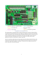
1
unzip GB_Python.zip
cd GB_Python
ls
The ls lists all the files in the directory. Most of them end in .py and are Python programs. The file
README.txt contains (amongst other info) instructions on how to install the packages you need to
run the Python programs.
Once you have the necessary packages installed, you can run the programs. For example, if want to
run the program leds-rg.py, which tests the LEDs (using the RPi.GPIO package, see below) type:
sudo python leds-rg.py
Why Different Program Versions?
There are two General Purpose Input Output (GPIO) packages for Python: RPi.GPIO and WiringPi
for Python. The programs that come in two versions (like leds-rg.py and leds-wp.py) are
using these different packages.
It is desirable to have the both these packages because neither of them yet offers a fully finished set of
capabilities (but most of the capabilities are covered between them). RPi.GPIO’s weakness is the lack
of hardware PWM (pulse width modulation) used with the motor program. WiringPi’s weakness is the
lack of pull-up facility required to use the buttons. If you want to use the full functionality of the
board you will need to install both. For some of the programs (for example, leds and ocol) no
special features are used, and you can use either package. The programs using the RPi.GPIO package
are the ones called filename-rg.py, whilst the ones using the WiringPi for Python package are
the ones called filename-wp.py.
Here is a list of all the Python test programs (at time of writing):
buttons-rg.py – buttons program using RPi.GPIO
leds-rg.py – leds program using RPi.GPIO
leds-wp.py – leds program using WiringPi
butled-rg.py – button and LED program using RPi.GPIO
motor-rg.py – motor program using software PWM and RPi.GPIO
motor-wp.py – motor program using hardware PWM and WiringPi
ocol-rg.py – relay switching program using RPi.GPIO
ocol-wp.py – relay switching program using WiringPi
atod.py – test for analogue to digital converter using SPI with spidev
dtoa.py – test for digital to analogue converter using SPI with spidev
dad.py – test for both D/A and A/D using SPI with spidev
potmot.py – test using A/D and motor using WiringPi and spidev
Buffered I/O, LEDs, and Pushbuttons
There are 12 pins which can be used as input or output ports. Each can be set to behave either as an
input or an output, using a jumper. Note that the terms ‘input’ and ‘output’ here are always with
respect to the Raspberry Pi: in input mode, the pin inputs data to the RPi; in output mode it acts as
14