1
Introduction to pcDuino
Lifeng Zhao and Jingfeng Liu
Content
Introduction .......................................................................................................................... 1
Chapter 1 Hardware and Software Introductions of pcDuino ................................................... 2
Required Accessories................................................................................................................. 4
pcDuino board I/O interface description .................................................................................. 6
Ubuntu ...................................................................................................................................... 7
Ubuntu in NAND flash ............................................................................................................... 7
How to install Ubuntu using microSD cards ...................................................................... 8
Burn the kernel in Linux PC ............................................................................................. 10
Burn the kernel in MAC OS PC......................................................................................... 11
How to install Ubuntu using LiveSuit .............................................................................. 13
Ubuntu in bootable microSD card ........................................................................................... 13
Backup NAND to a SD card, and boot from SD card................................................................ 17
Android.................................................................................................................................... 26
Android in NAND flash ............................................................................................................ 26
How to install Android using microSD card ..................................................................... 27
How to install Android using LiveSuit .............................................................................. 30
Use pcDuino as an mini PC platform ....................................................................................... 31
pcDuino and Ubuntu ....................................................................................................... 31
pcDuino and Android ...................................................................................................... 32
Chapter 2 Introduction of Ubuntu for pcDuino ...................................................................... 33
pcDuino Ubuntu File Directory Structure ............................................................................... 33
Linux Commands ..................................................................................................................... 35
Using USB WiFi Dongle ........................................................................................................... 38
Using USB Sound Card with Audio Input/output .................................................................... 42
Use 3G Cellular USB Dongle (Huawei E303s) .......................................................................... 43
Use Bluetooth USB Dongle ...................................................................................................... 45
Chapter 3 C Language and Arduino type IDE for pcDuino ....................................................... 48
Toolchain of the Arduino library.............................................................................................. 48
Command line style................................................................................................................. 48
Arduino library and samples ................................................................................................... 62
UART ................................................................................................................................ 62
ADC.................................................................................................................................. 66
PWM................................................................................................................................ 68
GPIO ................................................................................................................................ 71
I2C ................................................................................................................................... 72
SPI .................................................................................................................................... 74
Arduino IDE ............................................................................................................................. 77
Chapter 4 Introduction of Python on pcDuino ....................................................................... 86
Chapter 5 SimpleCV and OpenCV on pcDuino ........................................................................ 90
SimpleCV ................................................................................................................................. 90
OpenCV ................................................................................................................................... 93
Chapter 6 Cloud 9 on pcDuino ............................................................................................ 101
Chapter 7 Use Arduino Uno with pcDuino ........................................................................... 108
Simple Experiment: Blink ...................................................................................................... 108
ArduBlock .............................................................................................................................. 109
Chapter 8 Sratch on pcDuino .............................................................................................. 114
Appendix
How
to
build
pcDuino ..............................................................................116
kernel
for
Introduction
Recently, there is a wave of open hardware movement that begins with Arduino, which is a
simple AVR microprocessor (MCU) but powered by simple GUI and the complete open hardware
ecosystem. More recently, there is a trend toward ARM powered mini PC, which is represented
by Raspberry Pi, and more lately Beagle Board. Early this year, LinkSprite released a powerful mini
PC platform that combines the benefit of an ARM based mini PC and Arduino ecosystem: pcDuino,
which represents pc + Arduino. pcDuino is pin to pin compatible with Arduino so that existing
Arduino shields can be installed on pcDuino with a simple translation board (T-board). By being
compatible with Arduino ecosystem, pcDuino is a platform that bridges the power of open
software linux and the power of open hardware.
In this book, we are going to introduce how to get started with pcDuino. First, we will introduce
the hardware and software features of pcDuino.
You can always check pcduino.com, SFE learning center.
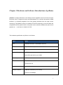
The following topics will be discussed in this book:
Hardware and software introductions of pcDuino
Introduction of Ubuntu for pcDuino
C Language and Arduino type IDE on pcDuino
Introduction of python on pcDuino
SimpleCV and openCV on pcDuino
Could9 on pcDuino
Scratch on pcDUino
A complete project: Rover, a WiFi video surveillance remote control robot
Introduction of Android on pcDuino
1
Chapter 1 Hardware and Software Introductions of pcDuino
pcDuino is a high performance, cost effective mini PC platform that runs PC like OS such
as Ubuntu Linux. It outputs its screen to HDMI enabled TV or monitor via the built in HDMI
interface. It is specially targeted for the fast growing demands from the open source
community. The platform could run full blown PC like OS with easy to use tool chain and
compatible with the popular Arduino ecosystem such as Arduino Shields and open source
projects etc. It can also run Android 4.0 ICS.
The hardware specification of pcDuino is as follows:
Items
Details
CPU
AllWinner A10 SoC, 1GHz ARM Cortex A8
GPU
OpenGL ES2.0, OpenVG 1.1 Mali 400 core
DRAM
1GB
Onboard Storage
2GB Flash
Micro-SD card slot for up to 32GB
Video Output
HDMI
OS
Linux3.0 + Ubuntu12.04
Android ICS 4.0
Extension Interface
Arduino Headers
Network interface
USB WiFi extension (not included)
Ethernet 10/100Mbps
2
Power
5V, 2A
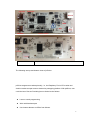
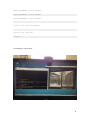
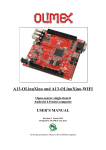
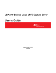
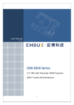
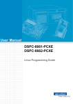
The following are top and bottom views of pcDuino:
pcDuino targets two markets primarily, i.e., the Raspberry Pi mini PC market and
Arduino market as open-source electronics prototyping platform. With pcDuino, user
could do lots of fun stuff including but not limited to the follows:
Learn or teach programming
Work with hardware part
Use Internet browser or Office from Ubuntu
3
Learn Ubuntu linux
Create media center with XBMC
Play game
DIY projects
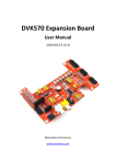
Required Accessories
Micro-USB port power adaptor ( 5V, 2000mA). Note: Pay attention to the micro USB cable
used. This USB cable must be able to carry large current as large as 2A. We have seen
lots of issues related to usage of weak USB cable.
A monitor/Display with HDMI port
HDMI cable
4
If you don’t have a HDMI monitor, you can use HDMI to DVI cable to connect to a DVI
monitor or a HDMI to VGA cable to connect to a VGA monitor.
USB keyboard (must)
USB Hub and USB mouse ( optional but strongly recommended )
Some Dupont wires to connect pcDuino with test devices
Micro-SD card and its card reader. Recommended to have two 2GB or above cards, one
for kernel upgrade, and the other one for Ubuntu upgrade.
Note:
Before using pcDuino, connect pcDuino with the devices correctly:
USB host port => USB hub => keyboard & mouse
HDMI port => HDMI cable => HDMI display
5
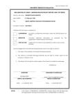
pcDuino board I/O interface description
The detailed schematics can be downloaded from:
https://s3.amazonaws.com/pcduino/Hardware/PC+Duino_V01-20130128.pdf
Here is the list of I/O interfaces on pcDuino board.
1. 14 digital pins for GPIO: GPIO max out current is 4mA.
2. One UART RX, one UART TX
3. Two PWM pins, support up to 24MHz.
4. Six ADC pins, ADC 0 and ADC 1 are 6 bits resolution, while the rest are 10 bits
resolution.
5. Four SPI pins
6. Two I2C pins
It supports onnecting any Arduino shield with pcDuino via any of the above I/O interfaces.
It allows using pcDuino with the same code used in Arduino.
6
Software
pcDuino supports both Ubuntu Linux and Android 4.0 ICS. When the book is written, the
latest release version of Ubuntu for pcDuino is 20130531.
Ubuntu
The factory default installation is Ubuntu in NAND flash. Ubuntu can boot from either
NAND flash or a bootable microSD card.
Ubuntu in NAND flash
If we want to reinstall Ubuntu or update Ubuntu in NAND flash, there are two options:
7
Install Ubuntu using microSD cards.
Install Ubuntu using through USB port using Livesuit.
In the following we are going to introduce each one.
How to install Ubuntu using microSD cards:
The installation process involves two steps:
1) Install Linux kernel (use microSD card #1) and
2) Install Ubuntu file system (use microSD card #2 or a USB flash drive, which
needs to be formatted as FAT).
The microSD card should be 2GB minimal.
In every pcDuino ubuntu release, there are two versions of kernel image. One is
for Phonexcard tool that is used to create microSD card #1 (This is the same file that is
used by Livesuit, which will be discussed later). The other is for Win32DiskImager
(windows) or dd (under linux) that is used to create microSD card #1.
Phonexcard can be downloaded from
https://s3.amazonaws.com/pcduino/Tools/PhoenixCardV306_20120302.rar
8
Win32DiskImager can be downloaded from:
https://s3.amazonaws.com/pcduino/Tools/win32diskimager-v0.7-binary.zip
or
http://sourceforge.net/projects/win32diskimager
9
Burn the kernel in Linux PC
a) Insert the micro-SD card to Linux PC or pcDuino, the card will be mounted automatically. To
continue, un-mount all the partitions on the card. For example,
If the SD has two partitions:
$ sudo umount /dev/mmcblk0p1
$ sudo umount /dev/mmcblk0p2
b) Then
burn
the
downloaded
and
unzipped
image
file
(a10_kernel_disk32imager_20130403.img) to the micro-SD card with the following
command:
$ sudo dd if=/udisk/a10_kernel_disk32imager_20130403.img of=/dev/mmcblk0
bs=1M
$ sudo sync
The of=/dev/mmcblk0 points to the micro-SD card.
Cautions: Don’t use “of=/dev/xxx” to point to your hard disk. It will destroy the contents in
your hard disk.
Now the micro-SD card is ready for use to burn the OS image to internal flash.
c) Burn the OS image to internal flash from micro-SD card
i. Plug the micro-SD card to the pcDuino, power on the board, and then wait for one minute
ii. Eject the TF card and reset the device. If you see the RX LED stays on, and the TX LED is
blinking, the kernel is updated successfully
10
Burn the kernel in MAC OS PC
a) Open the terminal in MacOS, insert the micro-SD card, the card will be mounted
automatically. To continue, un-mount all the partitions on the card. For example,
If the SD has two partitions:
$ sudo umount /dev/disk1s1
$ sudo umount /dev/disk1s2
If the SD card is failed to umount, you can use the following script to force umount:
$ sudo diskutil umount force /dev/disk1s1
$ sudo diskutil umount force /dev/disk1s2
b) Then
burn
the
downloaded
and
unzipped
image
file
(a10_kernel_disk32imager_20130403.img) to the micro-SD card with the following
command:
$ sudo dd if=/udisk/a10_kernel_disk32imager_20130403.img of=/dev/disk1
bs=1m
The of=/dev/disk1 points to the micro-SD card. After this command is complete, your Mac PC
will pop up the message “can’t identify the SD card” that indicates the file system in your
card is unknown to Mac PC now.
Cautions: Don’t use “of=/dev/xxx” to point to your hard disk. It will destroy the contents in
your hard disk.
Now the micro-SD card is ready for use to burn the OS image to internal flash.
11
c) Burn the OS image to internal flash from micro-SD card
i. Plug the micro-SD card to the pcDuino, power on the board, and then wait for one minute
ii. Eject the TF card and reset the device. If you see the RX LED stays on, and the TX LED is
blinking, the kernel is updated successfully
After we create microSD card #1, insert microSD #1 into the SD slot, and power cycle the
board. When the board starts to burn image file from SD card to flash, the TX LED will
blink slowly. Wait for about one minute, if the kernel is updated successfully, the LEDs will
be off.
Now, we are ready to flash Ubuntu file system to NAND flash. In every pcDUino Ubuntu
release, there is a file ball named Ubuntu, this is Ubuntu file system. Download the Ubuntu
file, and unzip it to get two files like these:
-
Update.sh: shell script for Ubuntu update
-
Ubuntu_xxx.img: image file for Ubuntu
Copy the two files to micro SD #2 or a USB flash drive, which must be formatted as FAT.
Power cycle pcDuino, you will see booting information on the screen, and plug in micro
SD #2 or USB flash drive when the message showing that it is looking for a disk
containing Ubuntu file system. The screen will shows “It will take about 10 minutes to
finish…”. Please wait patiently and the screen will prompt that it finished updating. When
that is done, remove the microSD card, and power cycle pcDuino.
Tips:
The microSD card #1 is specially created to allow it to be recognized by the ROMBOOT of
the board. To avoid the unexpected update of pcDuino, we can use the PhoenixCard to
restore it to normal and clean card
12
i. Plug your micro-SD card to your PC, run “PhoenixCard.exe”.
ii. Select the micro-SD card in the disk scroll window, and choose “Format to Normal” to
restore the card.
How to install Ubuntu using LiveSuit:
LiveSuit is a free tool which can upgrade firmware by USB device. To use this tool, you must install
two USB drivers. You can download the tool and drivers and read the user manual from:
https://s3.amazonaws.com/pcduino/Tools/Livesuit.rar
Note: LiveSuit is not very stable on Windows Vista or Windows 7, and it does not work well on 64
bits CPU. So this tool is not recommended.
Ubuntu in bootable microSD card:
In every pcDUino Ubuntu release, there is a file named SD bootable image. This file is
intended to create a bootable microSD card, so we can put all of our application and data
on the SD card instead of the space-limited NAND flash.
Steps:
1. Download the bootable microSD card image.
2. Unzip it and get xxx.img
13
3. Burn the unzipped image file above to the micro-SD card with win32diskimager or
dd in Linux PC or pcDuino
4. Plug the micro-SD card into pcDuino and power cycle pcDuino.
5. Ubuntu will be up running.
By default, the file system only uses 2GB. If you have a more space on your SD card, it is
not used by default.
We are going to use a script to expand the file system to the whole SD card.
$wget
https://s3.amazonaws.com/pcduino/SampleCode/System/expandFS/expand
_sdcard_rootfs.sh
$sudo bash ./expand_sdcard_rootfs.sh
14
After the expansion, we reboot pcDuino by:
$sudo reboot
After reboot, we run:
$sudo resize2fs /dev/mmcblk0p2
15
Check the storage space again using
16
$df -h
Backup NAND to a SD card, and boot from SD card
pcDuino has an onboard NAND of 2GB. When we are doing heavy duty project
development, we can easily eat up all the space. When that happens, we need a way to
move all the program and data from NAND to a SD of larger capacity and make that SD
bootable.
The key function we are going to use is:
make_mmc_boot “Clone system from nand to mmc card”
This function will copy the entire content in NAND to a SD card. This is equivalent
to flash an mmc-boot image. The benefit is that users still keep their own program/data.
When the space of NAND is not enough, we can use the SD card to replace the system
in NAND.
When the book is written, the latest image release is 20130531. In the original image
20130513, the above mentioned function is not there in board-config. We need to do an
update in board-config to make it available.
There are two ways to run board-config. One is to run that after reset. The other is to run it
in terminal.
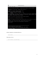
In the following, we are going to use the second approach. We type:
17
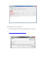
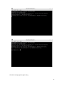
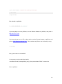
$sudo board-config.sh
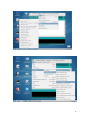
Next, we are going to choose ‘Update’:
18
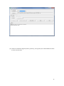
Then we choose ‘config’:
After that, pcDuino will check for update:
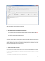
Press ‘Y’, and after the update is down, exit and re-run:
19
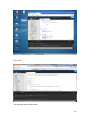
$sudo board-config.sh
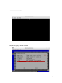
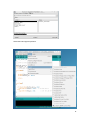
The option “make_mmc_boot” will display in the menu:
Plug in a SD card (in our case, a card of 16GB) to the SD slot, and press “ENTER”:
20
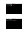
It takes some time to backup:
After a long wait, we will get the following message:
21
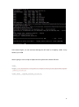
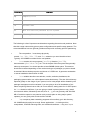
We reboot pcDuino, and check the storage space using:
$df –h
22
In the above figure, we can see that although the SD card is of capacity 16GB, it only
shows up as 2GB.
We are going to use a script to expand the file system to the whole SD card.
$wget
https://s3.amazonaws.com/pcduino/SampleCode/System/expandFS/expand
_sdcard_rootfs.sh
$sudo bash ./expand_sdcard_rootfs.sh
23
After the expansion, we reboot pcDuino by:
$sudo reboot
After reboot, we run:
sudo resize2fs /dev/mmcblk0p2
24
Check the storage space again using
25
$df -h
We can see that we get a full access to the SD card.
Android
The factory default installation is Ubuntu in NAND flash.
Android in NAND flash:
If we want to reinstall Android or update Android in NAND flash, there are two options:
Install Ubuntu using microSD cards.
Install Ubuntu using through USB port using Livesuit.
In the following we are going to introduce each one.
26
How to install Android using microSD card:
1. Download the Android operating system for pcDuino
The download link is:
http://www.pcduino.com/?page_id=14
Find the link for Android image, download it and get one file with .img extension.
Phonexcard can be downloaded from
https://s3.amazonaws.com/pcduino/Tools/PhoenixCardV306_20120302.rar
2. Write pcDuino Android image to micro-SD card
(a) Plug your micro-SD card to your PC, run “PhoenixCard.exe”. You will see something like this:
27
(b) Choose the Android image file pcduino_Android_ xxx.img that you’ve downloaded and write
it to the micro-SD card
28
After a few minutes, the micro-SD card is ready to use.
3. Burn the OS image to internal flash from micro-SD card
a) Plug the micro-SD card to the pcDuino and then power on the board. Wait for about four
minutes
b) Eject the micro-SD card and reset the device
* We have a catch in step (a). We don't have any LED to indicate when the boot image is burned
completely unless you connect the hyperterminal to pcDuino, so please wait for four minutes
patiently. Moreover, please eject the TF card before resetting the device. Otherwise, it will start
to burn the OS image again if the TF card is inserted.
4. Restore the micro-SD card created
The micro-SD card is specially created to allow it to be recognized by the ROMBOOT of the board.
To avoid the unexpected update of the Android OS, use the PhoenixCard to restore it to normal
and clean card
iii. Plug your micro-SD card to your PC, run “PhoenixCard.exe”.
29
iv. Select the micro-SD card in the disk scroll window, and choose “Format to Normal” to
restore the card.
How to install Android using LiveSuit:
LiveSuit is a free tool which can upgrade firmware by USB device. To use this tool, you must install
two USB drivers. You can download the tool and drivers and read the user manual from:
https://s3.amazonaws.com/pcduino/Tools/Livesuit.rar
Note: LiveSuit is not very stable on Windows Vista or Windows 7, and it does not work well on 64
bits CPU. So this tool is not recommended.
30
Use pcDuino as an mini PC platform
1) pcDuino and Ubuntu
pcDuino & Ubuntu support customized Ubuntu linux 12.04 that is specially optimized for running
on ARM cortex platform with limited DRAM and NAND flash support. The device could be
operated with the USB mouse and keyboard. The supported application list consists of the
follows:
Items
Details
Terminal
Use build in “LXTerminal” application from desktop
Launch terminal application, run standard linux commands or vi
editor etc.
File browser
Internet browser
Office
Movie player
Servers
Development
Launch C/C++ compile (use gcc), assembly and execution
Use build in File Manager from desktop
Used for typical file management
Use chromium web browser from desktop
Support HTML5
Use Document Viewer from desktop for PDF file view
Use Gnumeric from desktop for Excel file view and edit
Use AbiWord from desktop for Word file view and edit
Use MPlayer from desktop
Could playback audio, video and image
VNC server
SSH
Arduino IDE for pcDuino
31
Note:
The root user and password are “ubuntu”.
2) pcDuino and Android
pcDuino board supports customized android 4.0 that is specially optimized for HD-TV output
display devices. The device could be operated with the USB mouse and keyboard. The supported
application list consists of but not limited the follows:
Items
Details
File browser
Use build in File Manager
Used for typical file management
Use web browser from desktop or Google Search widget
Support HTML5
Internet browser
Calendar
Google Calendar
Gmail
Visit Gmail accounts
People
Google contacts apps
App Store
Use Google “play store” to download third-party apps
Music
Movie player
Built-in Super-HD Player to play local movies
Android built-in music player
32
Chapter 2 Introduction of Ubuntu for pcDuino
pcDuino Ubuntu File Directory Structure
Ubuntu adheres to the Filesystem Hierarchy Standard for directory and file naming. This standard
allows users and software programs to predict the location of files and directories. The root level
directory is represented simply by the slash /. At the root level, all Ubuntu systems include these
directories:
Directory
Content
bin
Essential command binaries
boot
Static files of the boot loader
dev
Device files
etc
Host-specific system configuration
home
User home directories
lib
Essential shared libraries and kernel modules
media
Contains mount points for replaceable media
mnt
Mount point for mounting a file system temporarily
proc
Virtual directory for system information (2.4 and 2.6 kernels)
root
Home directory for the root user
sbin
Essential system binaries
sys
Virtual directory for system information (2.6 kernels)
33
Directory
Content
tmp
Temporary files
usr
Secondary hierarchy
var
Variable data
srv
Data for services provided by the system
opt
Add-on application software packages
The following is a list of important considerations regarding directories and partitions. Note
that disk usage varies widely given system configuration and specific usage patterns. The
recommendations here are general guidelines and provide a starting point for partitioning.
The root partition / must always physically
contain /etc, /bin, /sbin, /lib and /dev, otherwise you won't be able to boot.
Typically 150–250MB is needed for the root partition.
/usr: contains all user programs (/usr/bin), libraries (/usr/lib),
documentation (/usr/share/doc), etc. This is the part of the file system that generally
takes up most space. You should provide at least 500MB of disk space. This amount
should be increased depending on the number and type of packages you plan to install.
A standard Ubuntu desktop requires a minimum of 1.5GB here. A generous workstation
or server installation should allow 4–6GB.
/var: variable data like news articles, e-mails, web sites, databases, the
packaging system cache, etc. will be placed under this directory. The size of this directory
depends greatly on the usage of your system, but for most people will be dictated by the
package management tool's overhead. If you are going to do a full installation of just
about everything Ubuntu has to offer, all in one session, setting aside 2 or 3 GB of space
for /var should be sufficient. If you are going to install in pieces (that is to say, install
services and utilities, followed by text stuff, then X, ...), you can get away with 300–500
MB. If hard drive space is at a premium and you don't plan on doing major system
updates, you can get by with as little as 30 or 40 MB.
/tmp: temporary data created by programs will most likely go in this directory.
40–100MB should usually be enough. Some applications — including archive
manipulators, CD/DVD authoring tools, and multimedia software — may use/tmp to
34
temporarily store image files. If you plan to use such applications, you should adjust the
space available in /tmpaccordingly.
/home: every user will put his personal data into a subdirectory of this directory. Its
size depends on how many users will be using the system and what files are to be stored
in their directories. Depending on your planned usage you should reserve about 100MB
for each user, but adapt this value to your needs. Reserve a lot more space if you plan to
save a lot of multimedia files (pictures, MP3, movies) in your home directory.
Linux Commands
We briefly discuss some of the frequently used commands used in Ubuntu.
Changing Directory
The command for changing directory is cd.
You can go to the top of your file system by typing cd
/. Any directory change starting with /
will be relative to the top directory in the file system. Typing cd folder/subfolder, etc.
will change directory relative to were you are now in the filesystem (the working directory), so,
for example, if you are in the home directory, and you type
directory home/arduino, but if you had instead typed
cd arduino you will go into the
cd /arduino, Linux would have tried
to put you in an arduino directory at the top level of the file system (similar to C:\arduino on
windows), which on most systems won't exist.
Listing Files in a directory:
To do this, type ls.
This function 'lists' all the files in a directory. Adding -a to the command (ls
any hidden files in that directory. Adding -l (ls
-a) will also show
-l) will show the file's permissions, type,
owner and the date it was created/edited.
Change User
On the Ubuntu system, we can use command ‘su’ to switch to root user mode. As many
35
commands require root privilege, we can add ‘su’ to the beginning of the command.
root is the super user (administrator) on Linux. Sudo is the command which allows other users
to issue a command as the super user. sudo = "super user do". Operations that a normal user
aren't normally allowed to do can be done using sudo. The word is just a mash of super-do and
pseudo. USE SUDO WITH CAUTION! Sudo can be used to do a lot of damage to your system,
and there is often a reason your normal account isn't allowed to perform a certain
action. suro
rm -rf /* would completely delete everything in the filesystem, destroying
the system.
Install Software Package
Apt-get is the package or software manager on Debian/Ubuntu linux. Install is the operation for
apt-get to perform and the name of the package follows the keyword or action of install.
Multiple package names can be put on the line following install.
Compress and Uncompress Install Software Package
Tar is a very popular file format in Linux to zipped files. The biggest advantage is that it can uses
little CPU resources to zip files. It is only a packing utility, and it is not responsible for compression.
The compression is done by gzip and bzip2. Now let’s use file format *.tar, *.tar.gz, and *.tar.bz2
as examples:
If we want to compress and pack the directory ‘test’ under /var/tmp to the current directory,
$ tar -cvf
test.tar
test
The above command only packs directories and files, and doesn’t do compression.
$ tar -zcvf
test.tar.gz
test
The above command packs directories and files, and then compresses the pack using gzip.
36
$ tar -jcvf
test.tar.bz2
test
The above command packs directories and files, and then compresses the pack using bzip2.
The following command compares the size of different resulting files:
$ ll
test.tar*
-rw-r--r-- 1 Lee mock 10240 01-18 17:05 test.tar
-rw-r--r-- 1 Lee mock
357 01-18 17:06 test.tar.bz2
-rw-r--r-- 1 Lee mock
327 01-18 17:05 test.tar.gz
How to uncompress the files:
$ tar -xvf
test.tar
$ tar -xvf
test.tar.gz
$ tar -jxvf
test.tar.bz2
How to Uninstall / Delete / Remove Package
To uninstall package, we can use ‘dpkg –list’ to list all the installed software packages. Once found
out the installed packages, we can use ‘sudo apt-get --purge remove” command followed by the
package name to remove a certain package. For example:
$sudo apt-get --purge remove lighttpd
A recommended text editor
Nano is a handy text editor that is more handy to use compared to vi. To install it, run “$sudo
apt-get install nano”.
How to check kernel version
The following command is used to find out the version of kernel:
37
ubuntu@ubuntu:~$ cat /proc/version
Find CPU Information /Speed
You use the following command to display all information about the CPU:
ubuntu@ubuntu:~$ cat /proc/cpuinfo
How to check storage space left
To check space left, type:
$df -h
Using USB WiFi Dongle:
The recommended USB WiFi Dongle for pcDuino is RT5370.
When the USB WiFi dongle is inserted, we can check if the hardware is working or not by using:
$lsusb
The following is what we get when the WiFi dongle is inserted.
38
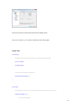
Open the “Network Connections” utility, under the “Preferences” submenu in the system menu.
Under the “Wireless” tab, click the “Add” button.
39
You can put whatever you like in the “Connection name” field, but you’ll need to have the SSID of
the network you want to connect to in the SSID field. Mode should default to “Infrastructure”,
which is correct for most networks, and the bottom four fields can be ignored.
40
In the “Wireless Security” tab, you can set the network security options for your network. We
won’t attempt to cover this, because it’s too big a topic; the fields should be pretty similar to
those on other devices, so copy the settings from something else if necessary.
41
Using USB Sound Card with Audio Input/output
The USB sound card we are using can be found at:
http://linksprite.com/wiki/index.php5?title=USB_Sound_Card_with_Audio_Input/Output
The USB sound driver is included in pcDuino’s ubuntu kernel.
To install the applications, please use:
$sudo apt-get install audacity
42
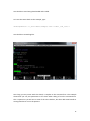
$sudo apt-get install pulseaudio pavucontrol
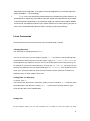
The following is the screen shot of Audacity. We can record and listen to sound.
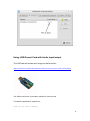
Use 3G Cellular USB Dongle (Huawei E303s)
We go through the steps to use 3G cellular USB dongle (Huawei E303s) with pcDuino.
43
Install the necessary software modules:
usb_modeswitch libusb-compat libusb-1.0.0 usb-modeswitch-data
Libusb-1.0.0 can be installed using:
$sudo apt-get install libusb-1.0.0
We also need:
$sudo apt-get install libusb-dev
ubuntu@ubuntu:~/Downloads/usb-modeswitch-1.2.6$ sudo make install
sed
's_!/usr/bin/tclsh_!'"/usr/bin/tclsh"'_'
<
usb_modeswitch.tcl
>
usb_modeswitch_dispatcher
install -D --mode=755 usb_modeswitch /usr/sbin/usb_modeswitch
install -D --mode=755 usb_modeswitch.sh /lib/udev/usb_modeswitch
install -D --mode=644 usb_modeswitch.conf /etc/usb_modeswitch.conf
install -D --mode=644 usb_modeswitch.1 /usr/share/man/man1/usb_modeswitch.1
install -D --mode=755 usb_modeswitch_dispatcher /usr/sbin/usb_modeswitch_dispatcher
install -d /var/lib/usb_modeswitch
ubuntu@ubuntu:~/Downloads/usb-modeswitch-data-20130610$ sudo make install
install -d /usr/share/usb_modeswitch
install -d /etc/usb_modeswitch.d
install -D --mode=644 40-usb_modeswitch.rules /lib/udev/rules.d/40-usb_modeswitch.rules
install --mode=644 -t /usr/share/usb_modeswitch ./usb_modeswitch.d/*
44
Use Bluetooth USB Dongle
We cover how to use Bluetooth USB dongle on pcDuino. In this tutorial, the Bluetooth USB
dongle we used is the one from CuteDigi.
First, we need to install the following software module:
#sudo apt-get install gnome-bluetooth
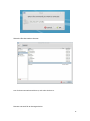
Plug in Bluetooth USB dongle, and check the USB device:
Run ‘bluetooth-sendto’ in the terminal:
45
Select the file that needs to be sent:
Scan for destination Bluetooth device, and select the device:
Now we can send file to the target device:
46
47
Chapter 3 C Language and Arduino type IDE for pcDuino
There are two flavors to use C langue on pcDuino, one is to use command line ‘make’ style. The
other one is to use Arduino style IDE. The Arduino IDE is included in version 20130531.
Toolchain of the Arduino library
The source code could be compiled with GCC tool chain. The GCC is pre-installed on the board.
You could enter gcc in Ubuntu terminal under any directory.
Cautious: you may need a bridge board to work with 5V Arduino Shield
All IO on the pcDuino board are 3.3V IO.
If the Arduino shield needs 5V input or 5V output, you need a bridge board for pcDuino.
Otherwise, you may damage your pcDuino board if you directly connect your shield with the
pcDuino.
Command line style
The quickest way to get going with Arduino sketches is to start with the samples so you have
a ‘template’ to guide you.
For parts of this guide to work, you’re pcDuino needs to be connected to the internet and
48
you also need a terminal session running on the pcDuino.
Setup (one time)
If not already done, set up git. Do this using the command:
ubuntu@ubuntu:~$ sudo apt-get install git
Make sure you’re in your home folder by typing
ubuntu@ubuntu:~$ cd
ubuntu@ubuntu:~$ pwd
/home/Ubuntu
Now download the distribution from github by typing
ubuntu@ubuntu:~$ git clone https://github.com/pcduino/c_enviroment
Cloning into 'c_enviroment'...
remote: Counting objects: 250, done.
remote: Compressing objects: 100% (166/166), done.
remote: Total 250 (delta 87), reused 232 (delta 69)
Receiving objects: 100% (250/250), 302.59 KiB | 78 KiB/s, done.
Resolving deltas: 100% (87/87), done.
You should now have a folder called c_enviroment. You can check by typing ls:
49
ubuntu@ubuntu:~$ ls
Desktop Documents Downloads Music Pictures Public Templates Videos arduino
c_enviroment sa
Initial Look Around
Change into the c_envoroment folder:
ubuntu@ubuntu:~$ cd c_enviroment
ubuntu@ubuntu:~/c_enviroment$ ls
Makefile hardware libraries output sample
50
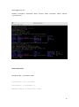
Now run make to make the libraries and the examples with the following command:
ubuntu@ubuntu:~/c_enviroment$ make
You should see a series of compile commands occurring without errors with the last line
being:
make[1]: Leaving directory `/home/ubuntu/c_enviroment/sample'
The resulting binary files are found in the output/test folder
ubuntu@ubuntu:~/c_enviroment$ cd output/test
ubuntu@ubuntu:~/c_enviroment/output/test$ ll
total 660
drwxrwxr-x 2 ubuntu ubuntu 4096 Apr 27 06:59 ./
drwxrwxr-x 3 ubuntu ubuntu 4096 Apr 27 06:49 ../
-rwxrwxr-x 1 ubuntu ubuntu 13868 Apr 27 06:58 adc_test*
-rwxrwxr-x 1 ubuntu ubuntu 28284 Apr 27 06:58 adxl345_test*
-rwxrwxr-x 1 ubuntu ubuntu 14209 Apr 27 06:58 interrupt_test*
-rwxrwxr-x 1 ubuntu ubuntu 13726 Apr 27 06:58 io_test*
-rwxrwxr-x 1 ubuntu ubuntu 13712 Apr 27 06:59 linker_button_test*
-rwxrwxr-x 1 ubuntu ubuntu 13907 Apr 27 06:59 linker_buzzer_test*
-rwxrwxr-x 1 ubuntu ubuntu 13689 Apr 27 06:59 linker_hall_sensor_test*
-rwxrwxr-x 1 ubuntu ubuntu 13760 Apr 27 06:59 linker_joystick_test*
-rwxrwxr-x 1 ubuntu ubuntu 13769 Apr 27 06:59 linker_led_bar_test*
-rwxrwxr-x 1 ubuntu ubuntu 13690 Apr 27 06:59 linker_led_test*
-rwxrwxr-x 1 ubuntu ubuntu 14290 Apr 27 06:59 linker_light_sensor_test*
51
-rwxrwxr-x 1 ubuntu ubuntu 13696 Apr 27 06:59 linker_magnetic_sensor_test*
-rwxrwxr-x 1 ubuntu ubuntu 14175 Apr 27 06:59 linker_potentiometer_test*
-rwxrwxr-x 1 ubuntu ubuntu 13658 Apr 27 06:59 linker_relay_test*
-rwxrwxr-x 1 ubuntu ubuntu 28530 Apr 27 06:59 linker_rtc_test*
-rwxrwxr-x 1 ubuntu ubuntu 14136 Apr 27 06:59 linker_sound_sensor_test*
-rwxrwxr-x 1 ubuntu ubuntu 13832 Apr 27 06:59 linker_temperature_sensor_test*
-rwxrwxr-x 1 ubuntu ubuntu 13714 Apr 27 06:59 linker_tilt_test*
-rwxrwxr-x 1 ubuntu ubuntu 13689 Apr 27 06:59 linker_touch_sensor_test*
-rwxrwxr-x 1 ubuntu ubuntu 40523 Apr 27 06:58 liquidcrystal_i2c*
-rwxrwxr-x 1 ubuntu ubuntu 40523 Apr 27 06:58 liquidcrystal_spi*
-rwxrwxr-x 1 ubuntu ubuntu 38242 Apr 27 06:59 pn532_readAllMemoryBlocks*
-rwxrwxr-x 1 ubuntu ubuntu 38238 Apr 27 06:59 pn532readMifareMemory*
-rwxrwxr-x 1 ubuntu ubuntu 38240 Apr 27 06:59 pn532readMifareTargetID*
-rwxrwxr-x 1 ubuntu ubuntu 38263 Apr 27 06:59 pn532writeMifareMemory*
-rwxrwxr-x 1 ubuntu ubuntu 13842 Apr 27 06:58 pwm_test*
-rwxrwxr-x 1 ubuntu ubuntu 32336 Apr 27 06:58 serial_test*
-rwxrwxr-x 1 ubuntu ubuntu 14449 Apr 27 06:58 spi_test*
-rwxrwxr-x 1 ubuntu ubuntu 18822 Apr 27 06:59 tone_test*
The source for each one is in the sample folder.
ubuntu@ubuntu:~/c_enviroment/output/test$ cd ../../sample
ubuntu@ubuntu:~/c_enviroment/sample$ ll
total 148
drwxrwxr-x 2 ubuntu ubuntu 4096 Apr 27 06:49 ./
52
drwxr-xr-x 7 ubuntu ubuntu 4096 Apr 27 06:58 ../
-rw-rw-r-- 1 ubuntu ubuntu 1368 Apr 27 06:49 Makefile
-rw-rw-r-- 1 ubuntu ubuntu 467 Apr 27 06:49 adc_test.c
-rw-rw-r-- 1 ubuntu ubuntu 6589 Apr 27 06:49 adx.c
-rw-rw-r-- 1 ubuntu ubuntu 5416 Apr 27 06:49 adxl345_test.c
-rw-rw-r-- 1 ubuntu ubuntu 92 Apr 27 06:49 core.h
-rw-rw-r-- 1 ubuntu ubuntu 830 Apr 27 06:49 interrupt_test.c
-rw-rw-r-- 1 ubuntu ubuntu 781 Apr 27 06:49 io_test.c
-rw-rw-r-- 1 ubuntu ubuntu 430 Apr 27 06:49 linker_button_test.c
-rw-rw-r-- 1 ubuntu ubuntu 1420 Apr 27 06:49 linker_buzzer_test.c
-rw-rw-r-- 1 ubuntu ubuntu 390 Apr 27 06:49 linker_hall_sensor_test.c
-rw-rw-r-- 1 ubuntu ubuntu 327 Apr 27 06:49 linker_joystick_test.c
-rw-rw-r-- 1 ubuntu ubuntu 2202 Apr 27 06:49 linker_led_bar_test.c
-rw-rw-r-- 1 ubuntu ubuntu 613 Apr 27 06:49 linker_led_test.c
-rw-rw-r-- 1 ubuntu ubuntu 1197 Apr 27 06:49 linker_light_sensor_test.c
-rw-rw-r-- 1 ubuntu ubuntu 404 Apr 27 06:49 linker_magnetic_sensor_test.c
-rw-rw-r-- 1 ubuntu ubuntu 647 Apr 27 06:49 linker_potentiometer_test.c
-rw-rw-r-- 1 ubuntu ubuntu 331 Apr 27 06:49 linker_relay_test.c
-rw-rw-r-- 1 ubuntu ubuntu 2505 Apr 27 06:49 linker_rtc_test.c
-rw-rw-r-- 1 ubuntu ubuntu 646 Apr 27 06:49 linker_sound_sensor_test.c
-rw-rw-r-- 1 ubuntu ubuntu 1145 Apr 27 06:49 linker_temperature_sensor_test.c
-rw-rw-r-- 1 ubuntu ubuntu 405 Apr 27 06:49 linker_tilt_test.c
-rw-rw-r-- 1 ubuntu ubuntu 389 Apr 27 06:49 linker_touch_sensor_test.c
-rw-rw-r-- 1 ubuntu ubuntu 797 Apr 27 06:49 liquidcrystal_i2c.c
-rw-rw-r-- 1 ubuntu ubuntu 831 Apr 27 06:49 liquidcrystal_spi.c
53
-rw-rw-r-- 1 ubuntu ubuntu 2002 Apr 27 06:49 pitches.h
-rw-rw-r-- 1 ubuntu ubuntu 3149 Apr 27 06:49 pn532_readAllMemoryBlocks.c
-rw-rw-r-- 1 ubuntu ubuntu 1690 Apr 27 06:49 pn532readMifareMemory.c
-rw-rw-r-- 1 ubuntu ubuntu 1117 Apr 27 06:49 pn532readMifareTargetID.c
-rw-rw-r-- 1 ubuntu ubuntu 2326 Apr 27 06:49 pn532writeMifareMemory.c
-rw-rw-r-- 1 ubuntu ubuntu 498 Apr 27 06:49 pwm_test.c
-rw-rw-r-- 1 ubuntu ubuntu 2079 Apr 27 06:49 serial_test.c
-rw-rw-r-- 1 ubuntu ubuntu 785 Apr 27 06:49 spi_test.c
To view the contents of a sample sketch, (this example we’ll look at the contents of
linker_led_test.c) type:
ubuntu@ubuntu:~/c_enviroment/sample$ cat linker_led_test.c
/*
* LED test program
*/
#include <core.h>
int led_pin = 1;
void setup()
{
if(argc != 2){
goto _help;
}
led_pin = atoi(argv[1]);
54
if((led_pin < 0) || (led_pin > 13)){
goto _help;
}
pinMode(led_pin, OUTPUT);
return;
_help:
printf("Usage %s LED_PIN_NUM(0-13)n", argv[0]);
exit(-1);
}
void loop()
{
digitalWrite(led_pin, HIGH); // set the LED on
delay(1000); // wait for a second
digitalWrite(led_pin, LOW); // set the LED off
delay(1000); // wait for a second
}
Editing an Existing Sketch
You will probably want to change some of these samples as an initial play so will need a text
editor. We tend to use nano, but you may already have a favourite. If not, install nano by
typing:
ubuntu@ubuntu:~/c_enviroment/sample$ sudo apt-get install nano
55
You should see nano being downloaded and installed.
Let’s use the same sketch as the example, type:
ubuntu@ubuntu:~/c_enviroment/sample$ nano linker_led_test.c
You should see something like:
One thing you may notice with this sketch, it compiles to the command line. This example
shows how you can pass parameters to the sketch when calling it from the command line.
This is optional as you will see in some of the other sketches, but does add some benefit to
writing sketches to run on the pcDuino.
56
Creating Your Own Sketch
Now lets create our own sketch and work out how to compile it so it runs. It will be a button
on pin 7 that when pressed, turns on an LED on pin 8.
While in the sample folder, type:
ubuntu@ubuntu:~/c_enviroment/sample$ nano button_led.c
An empty nano screen should appear.
Copy and paste the following code into it. (Remember to paste in nano at the cursor, just
right click the mouse button).
#include <core.h> // Required first line to run on pcDuino
int ledPin = 8;
int buttonPin = 7;
// variables will change:
int buttonState = 0; // variable for reading the pushbutton status
void setup() {
// initialize the LED pin as an output:
pinMode(ledPin, OUTPUT);
// initialize the pushbutton pin as an input:
pinMode(buttonPin, INPUT);
}
57
void loop(){
// read the state of the pushbutton value:
buttonState = digitalRead(buttonPin);
// check if the pushbutton is pressed.
// if it is, the buttonState is HIGH:
if (buttonState == HIGH) {
// turn LED on:
digitalWrite(ledPin, HIGH);
}
else {
// turn LED off:
digitalWrite(ledPin, LOW);
}
}
Modify the Makefile and Compile
Now we need to add this new sketch to the Makefile in the samples folder. Open the
Makefile with nano (or your favorite text editor).
ubuntu@ubuntu:~/c_enviroment/sample$ nano Makefile
You will see a section that lists all the OBJS something like:
58
OBJS
=
io_test
adc_test
pwm_test
spi_test
adxl345_test
serial_test
liquidcrystal_i2c liquidcrystal_spi interrupt_test tone_test
OBJS
+=
linker_led_test
linker_potentiometer_test
linker_tilt_test
linker_light_sensor_test linker_button_test
OBJS
+=
linker_touch_sensor_test
linker_magnetic_sensor_test
linker_temperature_sensor_test linker_joystick_test
OBJS
+=
linker_rtc_test
linker_sound_sensor_test
linker_buzzer_test
linker_hall_sensor_test linker_led_bar_test linker_relay_test
OBJS += pn532_readAllMemoryBlocks pn532readMifareMemory pn532readMifareTargetID
pn532writeMifareMemory
We’re going to add a line to the end of this with the name of the scketch we just created:
OBJS += button_led
Note, we don’t put the .c on the end.
Save the file and exit nano using <CTRL>X with a y and <enter>.
We now run make by typing:
ubuntu@ubuntu:~/c_enviroment/sample$ make
You should see a whole bunch of text with the end being:
button_led.c -o ../output/test/button_led ../libarduino.a
59
If all went well, you can go to the output/test folder and find your executable you have
created:
ubuntu@ubuntu:~/c_enviroment/sample$ cd ../output/test/
ubuntu@ubuntu:~/c_enviroment/output/test$ ll
total 676
drwxrwxr-x 2 ubuntu ubuntu 4096 Apr 27 07:51 ./
drwxrwxr-x 3 ubuntu ubuntu 4096 Apr 27 06:49 ../
-rwxrwxr-x 1 ubuntu ubuntu 13868 Apr 27 07:51 adc_test*
-rwxrwxr-x 1 ubuntu ubuntu 28284 Apr 27 07:51 adxl345_test*
-rwxrwxr-x 1 ubuntu ubuntu 13668 Apr 27 07:51 button_led*
…..(not showing rest of listing here)
Run Your Sketch
To run it, once you have wired up a switch and led to the right pins, type:
ubuntu@ubuntu:~/c_enviroment/output/test$ ./button_led
To stop the program, <Ctrl>C
A Quick Re-Cap
Add #include <core.h> to the top of your sketch.
60
Create your sketch in the samples folder (if your familiar with linux, makefiles, and
compiling code, you could set up your own)
Add the filename to the Makefile in the samples folder in the OBJS section without the .c
Run make
Run the executable from the output/test folder.
You can introduce command line arguments into your sketch to make it more transportable.
61
Arduino library and samples
UART
Reference:
Please refer to the Serial class from Arduino (http://arduino.cc/en/Reference/Serial).
F u n c t i o ns
if (Serial)
available()
begin()
end()
find()
findUntil()
flush()
parseFloat()
parseInt()
peek()
print()
println()
read()
readBytes()
readBytesUntil()
setTimeout()
write()
serialEvent()
UART Rx and Tx pins are shared with GPIO 0 and 1. Thus, if you are using UART, please don’t call
pinMode to change function mode of GPIO 0 and 1.
Currently, the supported baud rates are: 300, 600, 1200, 2400, 4800, 9600, 19200, 38400, 57600
and 115200 Hz.
62
Sample
Accept the typing from the terminal, then print out the input in the second line. Both read and
write operations are via UART interfaces.
Setup
Plugin USB-to-serial cable to PC USB port and install usb_to_serial driver to PC
Check the windows computer device manager for com port device.
Run a terminal tool like “sercureCRT”, and configure the serial port parameters to 115200 8N1.
63
Then you can type on the terminal and see the output prints.
If you use Linux PC, you could use minicom tool for this sample.
Sample code
void setup() {
//Initialize serial with baudrate setting, the default config is SERIAL_8N1
int rate = 115200;
Serial.begin(rate);
//you will see the string on the terminal
Serial.println("Serial begin: ");
}
void loop() {
//if you type the character in the terminal, available() will return the size you typed
if (Serial.available() > 0) {
// read the incoming byte:
64
char thisByte = Serial.read();
//print it on the terminal with DEC format
Serial.print("I received: ");
Serial.println(thisByte, DEC);
}
delay(200);
}
65
ADC
Arduino functions
analogReference()
pcDuino has the internal reference voltage. For ADC0 and ADC1, the reference is 2V, for ADC2~5,
the refernece is 3.3V. Thus, this function doesn’t change the reference voltage which is different
from original Arduino board.
analogRead()
ADC0 and ADC1 are 6-bit ADC, the return value is from 0 ~ 63, ranging from 0V to 2V.
ADC2~ADC5 are 12-bit ADC, the return value is from 0 ~ 4095, means from 0V to 3.3V.
Notes:
1. If you want to measure the high voltage, you can purchase the bridge board for pcDuino, it
can measure max 5V input.
2. For ADC0 and ADC1, though this function will return in 4us, the actual conversion rate is
250Hz. So if the input voltage changed, it can be detected in 4ms. For ADC2~ADC5, this
function will return in 35us, the return value is the actual value measured.
Sample
Measure thedry battery’s voltage
Setup
Connect the battery’s N to any GND and P to the ADC1
66
Sample Code
Read the value of ADC
Int adc_id = 0;
void setup() {
//argv[1] store the adc id that will be measured.
//if no args, default adc_id is 0
if ( argc == 2 )
adc_id = atoi(argv[1]);
}
void loop() {
// get adc value
int value = analogRead(adc_id);
//delay some time in loop
delayMicroseconds(100000);
}
67
PWM
Reference
analogWrite()
- with value 0 to set the PWM IO to low level.
Notes:
1. PWM1 and PWM2 are hardware PWMs. They are set to 520Hz with 256 duty cycle level by
default. PWM1/3/4/5 are 5Hz with 10 duty cycle level by default. Thus, the actual duty level is
value*10/256. PWM1/3/4/5 are simulated by GPIO in software, so they couldn’t set high frequency.
If you need simulate high frequency and accurate PWM with software GPIO, the CPU will be in
very high use.
2. The six PWM pins are shared with GPIO, and PWM4/PWM5 pins are also shared with SPI IO. So
if you are using PWM, don’t call pinMode() or SPI function to specific IO.
Functions not implemented
tone()
noTone()
tone function can generate a square wave with the setting frequency and duration.
You can’t use tone function to play the ringtones as Arduino does, because pcDuino’s tone
function can work under just several frequency setting. We will improve this in future release.
An extend function will be provided for those who needs higher or lower frequency PWM. So far,
we couldn’t support 256 duty cycle level in every frequency. Assume the max duty cycle in this
frequency is max_level, the actual level will be level * max_level/256. This function is also useful
for tone() function.
68
PWM1/3/4/5 will be improved in future release. The ultimate goal is to provide 500Hz support with
256 duty cycle.
Sample
Use PWM to control buzzer to make sound in different frequency
Setup
A buzzer connect to PWM1
Sample code
int pwm_id = 1;
int duty_level = 128;
void setup() {
//set the default freq (#define default_freq 0)
//PWM0/3/4/5, default_freq is 5Hz, and PWM1/2 is 520Hz
if ( argc > 1 )
pwm_id = atoi(argv[1]);
if ( argc > 2 ) //duty level can be 0 ~ 256
duty_level = argv[2];
69
//start the PWM
analogWrite(pwm_id, duty_level);
}
void loop() {
//delay in loop
delay(10);
}
70
GPIO
Reference functions
pinMode()
digitalRead()
digitalWrite()
pulseIn()
Sample
Turn on or off LED by pressing and releasing the button connected to the GPIO
Setup
Connect the shield to the GPIO1 and connect the LED to GPIO5
Sample code
int led_pin = 5;
71
int btn_pin = 1;
void setup() {
if ( argc == 3 ) {
btn_pin = atoi(argv[1]);
led_pin = atoi(argv[2]);
}
//set the gpio to input or output mode
pinMode(led_pin, OUTPUT);
pinMode(btn_pin, INPUT);
}
void loop() {
//press btn_pin to turn on LED
int value = digitalRead(btn_pin);
if ( value == HIGH )
{ // button pressed
digitalWrite(led_pin, HIGH); // turn on LED
} else { // button released
digitalWrite(led_pin, LOW); // turn off LED
}
delay(100);
}
I2C
Reference function
72
Please refer to the Wire class (http://arduino.cc/en/Reference/Wire)
F u n c t i o ns
begin()
requestFrom()
beginTransmission()
endTransmission()
write()
available()
read()
onReceive()
onRequest()
pcDuino I2C is set 200KHz, 7-bit version, master only by default
Future improvements:
Function will be provided to users to allow them to configure the I2C frequency. And we will also
support 10-bit mode.
Sample
Read the X, Y and Z coordinates for triple axis via I2C interface
Setup
Connect the I2C port of Triple-Axis with pcDuino
73
SPI
Reference functions
Please refer to the SPI class. (http://arduino.cc/en/Reference/SPI)
F u n c t i o ns
begin()
end()
setBitOrder()
setClockDivider()
setDataMode()
transfer()
pcDuino SPI only works in master mode. The max speed is 12MHz. Clock divider can be
2/4/8/16/32/64/128.
Note that calling the setClockDivider() function just saves the setting of clock divider but without
the real clock change. It works when the transfer function called.
74
Sample
To read an SPI flash ID of M25P16
Setup
GND ---------- GND
V3.3
----------
3.3V
DO ----------
SPI_MISO
DI
----------
SPI_MOSI
CS
----------
SPI_CS
CLK ---------
SPI_CLK
Sample code
int ReadSpiflashID(void) {
char CMD_RDID = 0x9f;
char id[3];
int flashid = 0;
memset(id, 0x0, sizeof(id));
75
id[0] = SPI.transfer(CMD_RDID, SPI_CONTINUE);
id[1] = SPI.transfer(0x00, SPI_CONTINUE);
id[2] = SPI.transfer(0x00, SPI_LAST);
//MSB first
flashid = id[0] << 8;
flashid |= id[1];
flashid = flashid << 8;
flashid |= id[2];
return flashid;
}
void setup() {
// initialize SPI:
SPI.begin();
}
void loop() {
//MSB first
printf("spi flash id = 0x%x\n", ReadSpiflashID());
delay(2000);
}
76
Arduino IDE
pcDuino Image 20130531 has Arduino IDE built-in.
We added a new board type ‘pcDuino’. By default, the board type is pcDuino.
77
78
Now let’s look at one example. We will use Linker kit button module and Linker kit LED module to
implement a simple function: when the button got pressed, and LED will turn on.
The code is shown below:
/*
* Linker kit button and LED test
*/
#include <core.h>
int led_pin = 2;
int button_pin =1;
void setup()
79
{
pinMode(led_pin, OUTPUT);
pinMode(button_pin, INPUT);
return;
}
void loop()
{
if( digitalRead(button_pin)== HIGH)
digitalWrite(led_pin, HIGH);
// set the LED on
else
digitalWrite(led_pin, LOW);
// set the LED off
}
Launch the Arduino IDE for pcDuino, and click File->New.
80
Copy and paste the sample code into the new window:
81
Save file as the following and name the file as linker_button_led.
82
Select the board type as pcDuino:
83
Click the upload
button. A new window will pop up, and the code is running.
Hardware wise, the Linker button module is plugged to D1 and Linker LED module is plugged
to D2. When the button is not pressed, the LED is off.
84
85
Chapter 4 Introduction of Python on pcDuino
Python is a programming language that lets you work more quickly and integrate your systems
more effectively. You can learn to use Python and see almost immediate gains in productivity and
lower maintenance costs.
Python is pre-installed in the pcDuino Ubuntu image released after 20130531.
The sample python code can be downloaded from:
https://github.com/pcduino/python-pcduino
ubuntu@ubuntu:~$ git clone https://github.com/pcduino/python-pcduino
Cloning into 'python-pcduino'...
remote: Counting objects: 81, done.
remote: Compressing objects: 100% (43/43), done.
remote: Total 81 (delta 30), reused 76 (delta 30)
Unpacking objects: 100% (81/81), done.
ubuntu@ubuntu:~$
86
Let’s look around, and what’s inside:
ubuntu@ubuntu:~/python-pcduino$ ls -R
.:
README.md Samples pcduino setup.py
./Samples:
blink_led
./Samples/blink_led:
blink_led.py gpio
./Samples/blink_led/gpio:
__init__.py __init__.pyc
./pcduino:
__init__.py adc.py exceptions.py gpio.py pinmap.py pwm.py
Let’s look at the sample project blink_led. We install Linker kit LED module on D2 on Linker based shield.
87
The python code is shown below:
ubuntu@ubuntu:~/python-pcduino/Samples/blink_led$ more blink_led.py
#!/usr/bin/env python
# blink_led.py
# gpio test code for pcduino ( http://www.pcduino.com )
#
import gpio
import time
led_pin = "gpio2"
def delay(ms):
time.sleep(1.0*ms/1000)
88
def setup():
gpio.pinMode(led_pin, gpio.OUTPUT)
def loop():
while(1):
gpio.digitalWrite(led_pin, gpio.HIGH)
delay(200)
gpio.digitalWrite(led_pin, gpio.LOW)
delay(100)
def main():
setup()
loop()
main()
To execute the code, we run the following command:
ubuntu@ubuntu:~/python-pcduino/Samples/blink_led$ python blink_led.py
We can observe Linker LED module blinking.
89
Chapter 5 SimpleCV and OpenCV on pcDuino
pcDuino has the computational power to run computer vision applications, and enable many
projects that are impossible with Arduino. In this chapter, we are going to look at simple projects
with SimpleCV and OpenCV.
SimpleCV
Before we start, we need to make sure we have a UVC compatible USB camera handy.
Follow the following steps to install simpleCV:
$sudo apt-get install ipython python-opencv python-scipy python-numpy
python-setuptools python-pip
$sudo pip install https://github.com/ingenuitas/SimpleCV/zipball/master
$sudo apt-get install python-pygame
$sudo apt-get install python-imaging
We launch simpleCV by typing “$ simpleCV”. simpleCV is an interactive shell, and we can type the
commands here:
ubuntu@ubuntu:~$ simplecv
90
+-----------------------------------------------------------+
SimpleCV 1.3.0 [interactive shell] - http://simplecv.org
+-----------------------------------------------------------+
Commands:
"exit()" or press "Ctrl+ D" to exit the shell
"clear" to clear the shell screen
"tutorial" to begin the SimpleCV interactive tutorial
"example" gives a list of examples you can run
"forums" will launch a web browser for the help forums
"walkthrough" will launch a web browser with a walkthrough
Usage:
dot complete works to show library
for example: Image().save("/tmp/test.jpg") will dot complete
just by touching TAB after typing Image().
Documentation:
help(Image), ?Image, Image?, or Image()? all do the same
"docs" will launch webbrowser showing documentation
SimpleCV:1> cam=Camera()
VIDIOC_QUERYMENU: Invalid argument
VIDIOC_QUERYMENU: Invalid argument
VIDIOC_QUERYMENU: Invalid argument
VIDIOC_QUERYMENU: Invalid argument
91
VIDIOC_QUERYMENU: Invalid argument
VIDIOC_QUERYMENU: Invalid argument
VIDIOC_QUERYMENU: Invalid argument
SimpleCV:2> img=cam.getImage()
SimpleCV:3> img.show()
SimpleCV:5:
The following is a screenshot:
92
OpenCV
OpenCV is an open source computer vision package based on Python. In this post, we are going
to detail the steps to install OpenCV on pcDuino. Two examples are given, one is used to capture
an image through the USB camera, the other is to use OpenCV to to face recognition.
Installation Steps:
$ sudo apt-get -y install build-essential cmake cmake-qt-gui pkg-config libpng12-0
libpng12-dev libpng++-dev libpng3 libpnglite-dev zlib1g-dbg zlib1g zlib1g-dev pngtools
libtiff4-dev libtiff4 libtiffxx0c2 libtiff-tools
$sudo
apt-get
libavcodec-dev
-y
install
libjpeg8
libavcodec53
libgstreamer0.10-0
libjpeg8-dev
libavformat53
libgstreamer0.10-dev
libjpeg8-dbg
libavformat-dev
libxine1-ffmpeg
libjpeg-progs
ffmpeg
libgstreamer0.10-0-dbg
libxine-dev
libxine1-bin
libunicap2 libunicap2-dev libdc1394-22-dev libdc1394-22 libdc1394-utils swig libv4l-0
libv4l-dev python-numpy libpython2.6 python2.6-dev libgtk2.0-dev pkg-config
$sudo apt-get install libopencv-dev python-opencv
$sudo apt-get install python-dev
$sudo ln -s /usr/lib/arm-linux-gnueabihf/libjpeg.so /usr/lib
$sudo ln -s /usr/lib/arm-linux-gnueabihf/libfreetype.so /usr/lib
$sudo ln -s /usr/lib/arm-linux-gnueabihf/libz.so /usr/lib
93
$sudo easy_install PIL
$sudo pip install -v PIL
Example 1: Capture Image using OpenCV
#!/Users/brent/.virtualenvs/lumber/bin/python
import cv
cv.NamedWindow("w1", cv.CV_WINDOW_AUTOSIZE)
camera_index = 0
capture = cv.CaptureFromCAM(camera_index)
gx = gy = 1
grayscale = blur = canny = False
def repeat():
global capture #declare as globals since we are assigning to them now
global camera_index
global gx, gy, grayscale, canny, blur
frame = cv.QueryFrame(capture)
# import pdb; pdb.set_trace()
94
if grayscale:
gray = cv.CreateImage(cv.GetSize(frame), frame.depth, 1)
cv.CvtColor(frame, gray, cv.CV_RGB2GRAY)
frame = gray
if blur:
g = cv.CreateImage(cv.GetSize(frame), cv.IPL_DEPTH_8U, frame.channels)
cv.Smooth(frame, g, cv.CV_GAUSSIAN, gx, gy)
frame = g
if grayscale and canny:
c = cv.CreateImage(cv.GetSize(frame), frame.depth, frame.channels)
cv.Canny(frame, c, 10, 100, 3)
frame = c
cv.ShowImage("w1", frame)
c = cv.WaitKey(10)
if c==ord('='): #in "n" key is pressed while the popup window is in focus
gx += 2
gy += 2
elif c == ord('-'):
gx = max(1, gx-2)
gy = max(1, gy-2)
elif c == ord('x'):
gx += 2
95
elif c == ord('X'):
gx = max(1, gx-2)
elif c == ord('q'):
exit(0)
elif c == ord('b'):
blur = not blur
elif c == ord('g'):
grayscale = not grayscale
elif c == ord('c'):
canny = not canny
while True:
repeat()
Example 2: Face Recognition
Input Image:
96
Download the above image and save as “opencv_in.jpg”
Output Image:
97
#!/usr/bin/env python
#coding=utf-8
import os
from PIL import Image, ImageDraw
import cv
def detect_object(image):
grayscale = cv.CreateImage((image.width, image.height), 8, 1)
cv.CvtColor(image, grayscale, cv.CV_BGR2GRAY)
cascade
=
cv.Load("/usr/share/opencv/haarcascades/haarcascade_frontalface_alt_tree.xml
")
98
rect = cv.HaarDetectObjects(grayscale, cascade, cv.CreateMemStorage(), 1.1,
2,
cv.CV_HAAR_DO_CANNY_PRUNING, (20,20))
result = []
for r in rect:
result.append((r[0][0], r[0][1], r[0][0]+r[0][2], r[0][1]+r[0][3]))
return result
def process(infile):
image = cv.LoadImage(infile);
if image:
faces = detect_object(image)
im = Image.open(infile)
path = os.path.abspath(infile)
save_path = os.path.splitext(path)[0]+"_face"
try:
os.mkdir(save_path)
except:
pass
if faces:
draw = ImageDraw.Draw(im)
count = 0
99
for f in faces:
count += 1
draw.rectangle(f, outline=(255, 0, 0))
a = im.crop(f)
file_name = os.path.join(save_path,str(count)+".jpg")
#
print file_name
a.save(file_name)
drow_save_path = os.path.join(save_path,"out.jpg")
im.save(drow_save_path, "JPEG", quality=80)
else:
print "Error: cannot detect faces on %s" % infile
if __name__ == "__main__":
process("./opencv_in.jpg")
Download and save the above code to “ test_face.py”.
Run “python test_face.py” to execute.
100
Chapter 6 Cloud 9 on pcDuino
Cloud9 IDE (http://www.c9.io) is an online development environment for Javascript and
Node.js applications as well as HTML, CSS, PHP, Java, Ruby and 23 other languages.
We recommend that Cloud 9 IDE run on a SD card with capacity larger than 4GB. Please
refer to chapter 2 on how to migrate program/data from NAND to a SD card.
Install required packages
$ sudo apt-get install git libssl-dev python-software-properties
Build nodejs ( required by cloud9 IDE )
$ git clone git://github.com/joyent/node.git
$ cd node
$ git checkout v0.8.22
$ make
$ sudo make install
After nodejs installed, you can delete the source to save space.
Build cloud9 IDE
101
$ git clone https://github.com/ajaxorg/cloud9.git
$ cd cloud9/
$ npm install
Run cloud9 on pcDuino
$ ./bin/cloud9.sh -l 0.0.0.0
If you are going to run on pcDuino, use the Chrome browser on pcDuino, and point to
http://127.0.0.1:3131.
If you are going to run on a PC or other device, use the Chrome browser on pcDuino, and
point to http://board-ip-address:3131. The ip address of pcDuino can be found by using:
$ ifconfig
Run js test code on cloud9 IDE
It’s very easy to run js code from cloud9.
Just write the code ( example blink_led.js ), then press button “RUN” on menu bar.
Run on pcDuino:
102
Run on PC:
The following is the example code:
103
blink_led.js:
/**
* blink_led.js, simple node.js test code for pcduino (http://www.pcduino.com)
* base on the source code from https://github.com/jheising/node.pcduino.git
*/
var fs = require('fs');
var led_pin;
var INPUT = 0;
var OUTPUT = 1;
var LOW = 0;
var HIGH = 1;
function digitalWrite(pin, value)
{
fs.writeFileSync("/sys/devices/virtual/misc/gpio/mode/gpio" + pin, String(value));
}
function pinMode(pin, mode)
{
fs.writeFileSync("/sys/devices/virtual/misc/gpio/mode/gpio" + pin, String(mode));
}
function delay(ms)
{
104
var start = new Date().getTime();
for (var i = 0; i < 1e7; i++)
if ((new Date().getTime() - start) > ms) break;
}
function setup()
{
led_pin = 18;
pinMode(led_pin, OUTPUT);
}
function loop()
{
digitalWrite(led_pin, HIGH);
delay(1000);
digitalWrite(led_pin, LOW);
delay(1000);
}
function main()
{
setup();
while(1)
{
loop();
}
}
105
main();
Run C/C++ program on cloud9 IDE
Running C/C++ is almost the same as running a program from terminal.
Write your code first (example 00.pcDuino/blink_led.c ).
Run the following commands from command input box (at the bottom of cloud9 IDE):
cd 00.pcDuino/
g++ blink_led.c -larduino -I/usr/include/pcduino -o blink_led
./blink_led
The following is the example code:
blink_led.c
#include
int led_pin=18;
void setup()
{
pinMode(led_pin, OUTPUT);
}
106
void loop()
{
digitalWrite(led_pin, HIGH);
delay(100);
digitalWrite(led_pin, LOW);
delay(100);
}
107
Chapter 7 Use Arduino Uno with pcDuino
Theoretically speaking, we don’ need to use Arduino Uno with pcDuino as pcDuino has all
interface that can be offered by Arduino Uno. In the pcDuino ubuntu released after
20130531, there is Arduino IDE already embedded.
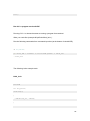
Simple Experiment: Blink
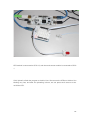
Take an Aduino Uno and plug to any available USB host port on pcDunino. The whole
setup is shown below:
108
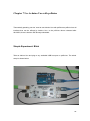
Launch Arduino IDE and open the sample code “Blink”:
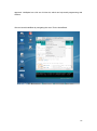
Click upload button, we can observe that the code is being uploaded to Arduino Uno, and
the LED on Arduino starts to blink when it is done uploading.
ArduBlock
ArduBlock is designed to make it easy to get start with programming Arduino and we
believe that electronic brick is more suitable for starter than breadboard or protoboard
109
approach. LinkSprite has a full set of Linker kit, which can help teach programming with
Arduino.
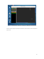
We can launch ArduBlock by navigating the menu Tools->ArduoBlock.
110
We can create a program by picking the elements in the left column to the work space in
right column:
111
Save the program to a file named ‘test’. The experiment setup is shown below:
112
LED module is connected to GPIO 13, and the touch sensor module is connected to GPIO
1.
Click ‘Upload’ to flash the program to Arduino Uno. We can see the LEDs on Arduino Uno
blinking very fast, and after the uploading is done, we can press touch sensor to turn
on/off the LED.
113
Chapter 8 Sratch on pcDuino
Sratch (http://scratch.mit.edu/) is a programming language for everyone. Create
interactive stories, games, music and art – and share them online.
pcDuino team developed a customized version of Scratch for pcDuino. The GPIO, PWM
and ADC pins can be accessed directly from Scratch panel.
Compared to the original version of Scratch, the following features are added:
Add support of hardware PWM, and ADC. The ADC is to read the voltage in units of
mV.
Add support of GPIO support.
Modify the UI.
Add support of Chinese language.
The install of scratch can be done using “apt-get install”.
The following are the installation steps:
1.$sudo apt-get update
2. If there is previous version of scratch installed, please remove “squeak-plugins-scratch”
by:
114
$sudo apt-get remove squeak-plugins-scratch
3. Install scratch by:
$sudo apt-get install pcduino-scratch
The GUI is as following:
115
Appendix
How to build kernel for pcDuino
The commands discussed below are on a regular X86 PC.
1. Download kernel source files from Github.
1.
$ git clone https://github.com/pcduino/kernel.git
Note:
This step only downloads the build environment.
There are some submodules from https://github.com/linux-sunxi/.
Source files of submodules will be downloaded when running “make” under
kernel/ directory for the first time
(or if the submodules have not been downloaded before when running
“make”)
2. Install required software and toolchain on PC for cross-compile
On x86 ubuntu, install the following packages using apt-get:
1.
$ sudo apt-get install build-essential git u-boot-tools texinfo texlive
ccache zlib1g-dev gawk
2.
$ sudo apt-get install bison flex gettext uuid-dev ia32-libs
Download the recommended linaro toolchain(choose the “arm hf crosscompiler for
Linux”):
https://launchpad.net/linaro-toolchain-binaries/+download
1.
$ tar jzxf gcc-linaro-arm-linux-gnueabihf-xxx_linux.tar.bz2 -C
your-path
116
2.
$ export
PATH=$PATH:your-path/gcc-linaro-arm-linux-gnueabihf-xxx_linux/bin/
3. Build Kernel Image
Run “make” under kernel/ directory ( Do not compile the source file under
kernel/linux-sunxi directory ).
1.
$ cd kernel/
2.
$ make
If no error occurs, a livesuitable image and a HW_pack will be in the output folder:
pcduino_a10_hwpack_YYYYMMDD.tar.xz ( includes uboot for mmc-boot,
kernel, and driver modules ).
pcduino_a10_kernel_livesuit_YYYYMMDD.img ( kernel image update by
livesuit )
Note:
For the first time, it will download the required source code from
https://github.com/linux-sunxi/.
For each time run “make”, it will apply the patch for pcduino.
The patch for pcduino is located at kernel/patch/ directory.
All the object files generated by compile tools saved in kernel/build directory.
Compile kernel under kernel/linux-sunxi directory will make the build
environment “dirty”.
If your have done it before. clean up by running “make mrproper” under
kernel/linux-sunxi.
117
4. Update pcDuino with your new kernel
The following commands should be run on pcDuino.
If you only want to update kernel and modules ( not desktop like ubuntu ), just unpack
hwpack file, and replace files on board:
a) update kernel for nand-boot board
1.
$ tar xvf pcduino_a10_hwpack_YYYYMMDD.tar.xz -C /tmp
2.
$ sudo mount /dev/nanda /boot
3.
$ sudo cp /tmp/kernel/* /boot -f
4.
$ sudo mv /lib/modules/3.4.29+ /lib/modules/3.4.29_old
5.
$ sudo cp /tmp/rootfs/lib/modules/3.4.29+ /lib/modules/ -ar
6.
$ sudo sync
7.
$ sudo umount /boot/
8.
$ sudo reboot
b) update kernel for mmc-boot board
1.
$ tar xvf pcduino_a10_hwpack_YYYYMMDD.tar.xz -C /tmp
2.
$ sudo mount /dev/mmcblk0p1 /boot
3.
$ sudo cp /tmp/kernel/* /boot -f
4.
$ sudo mv /lib/modules/3.4.29+ /lib/modules/3.4.29_old
5.
$ sudo cp /tmp/rootfs/lib/modules/3.4.29+ /lib/modules/ -ar
6.
$ sudo sync
7.
$ sudo umount /boot/
8.
$ sudo reboot
Note:
Hardwarelibs are closed source modules now, you can copy those modules
from /lib/modules/3.4.29_old:
118
$ sudo cp /lib/modules/3.4.29+_old/kernel/drivers/hardwarelib/
/lib/modules/3.4.29+/kernel/drivers/ -ar
5. Customize your kernel
You can change or add drivers for your own. Before compile, save all the source code you
changed/added under kernel/patch dir. ( this step can be done by running
“./make_kernel_patch.sh” under kernel/patch/linux-sunxi )
files under kernel/linux-sunxi may will be over written by the patch.
If you want to change kernel config file (add/remove some drivers), there is something
different.
Customize kernel config by running “make menuconfig”, then save it to patch directory
and re-build kernel.
1.
$ cd kernel/build/sun4i_defconfig-linux/
2.
$ make menuconfig ARCH=arm CROSS_COMPILE=arm-linux-gnueabihf-
3.
$ mv .config ./../patch/linux-sunxi/arch/arm/configs/sun4i_defconfig
-f
Follow step 3) to re-build kernel and step 4) to update pcDuino with your new kernel.
119