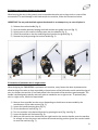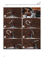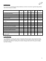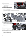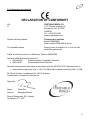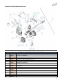
1
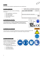
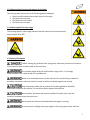
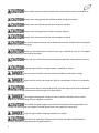
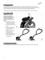
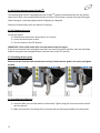
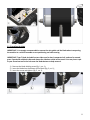
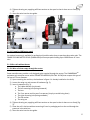
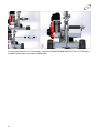
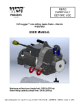
USER MANUAL SERIAL NUMBER: PWM100516 AND UP © 2015 Portable Winch Co. – All Rights Reserved www.600mh.com English Version – Printed in Canada Summary Introduction – p. 3 1.0 Safety guidelines – p. 3 1.1 Safety messages – p. 3 1.2 Labels – p. 4 1.2.1 Serial number label – p. 4 1.2.2 Sound pressure level label – p. 4 1.2.3 Read the user manual label – p. 4 1.2.4 Safety equipment label – p. 4 1.2.5 Warning label for potential dangers of the blade – p. 5 1.2.6 Warning label for slope usage – p. 5 1.3 Security information – p. 5 2.0 Pre-operation checks – p. 7 2.1 Upon reception – p. 7 2.2 Assembly and start-up – p. 8 2.2.1 Installing the handle – p. 8 2.2.2 Preparing and starting engine – p. 8 2.2.2.1 Engine Oil – p. 9 2.2.2.2 Gasoline (petrol) – p. 9 2.2.2.3 First use – p. 9 2.2.2.4 Oil level warning system (Oil AlertTM) – p. 10 2.2.2.5 Stopping the engine – p. 10 2.2.3 Installing the wire guide – p. 10 2.2.4 Installing the sliding foot – p. 10 2.2.5 Installing the blade – p. 11 3.0 Usage – p. 12 3.1 Installing the perimeter wire spool – p. 12 3.1.1 Spools mounted on a drum – p. 12 3.1.1.1 Frame for 1000 meter spool – p. 13 3.1.2 Wire coils without drums – p. 13 3.1.2.1 Wire coils that empty through the center – p. 13 3.1.2.2 Wire coils without a drum – p. 15 3.2 Moving the machine to the working zone – p. 16 3.3 Using the distance guide – p. 16 3.4 Self-propulsion – p. 16 3.5 Adjusting the stabilizer wheel – p. 17 3.6 Inserting the perimeter wire in the wire guide – p. 17 3.7 Burying the perimeter wire in the ground – p. 18 3.8 How to overcome an obstacle in the ground – p. 19 3.9 Insertion of perimeter wire in a tight corner – p. 19 4.0 Maintenance – p. 21 4.1 Belt adjustment – p. 21 4.1.1 Adjusting the engine belt - p. 22 4.1.2 Adjusting the blade transmission belt – p. 22 4.1.3 Adjusting the transmission belt tension – p. 22 4.2 Lubricating the blade transmission – p. 22 4.3 Storage – p. 23 4.4 Engine – p. 23 5.0 Additional Information – p. 23 5.1 Accessories – p. 23 5.2 Spare parts – p. 23 5.3 Warranty – p. 24 5.4 Declaration of conformity – p. 25 5.5 Technical data – p. 26 5.6 Sound power levels – p. 26 5.7 Vibration level – p. 26 5.8 Manufacturer – p. 26 Schedule I: Exploded views and parts lists – p. 27 2 Introduction Portable Winch Co. wishes to thank you for purchasing a PWM600MHTM Perimeter Wire Machine. This manual was written to help you make the best use of your new machine and to use it in the most secure way. READ IT CAREFULLY BEFORE USING THE MACHINE. For any problems or questions please refer to an authorized Portable Winch Co. dealer or contact us directly. 1.0 Safety guidelines The PWM600MHTM Perimeter Wire Machine is designed to bury electrical wires up to 4 mm in diameter at depth between 4 and 6 cm in grassy soil. The use of this machine implies serious risks of injury, property damage or even death. Do not underestimate its potential danger. 1.1 Safety messages Your safety and the safety of others are very important. You will find important safety messages in this manual. Read them carefully. These security messages are warning you of potential injuries to either yourself or others. Every safety message is preceded by a warning symbol CAUTION. and one of the following terms: DANGER, WARNING or These indicator words mean: You WILL be MORTALLY or SEVERELY INJURED if you do not follow these instructions. You COULD be MORTALLY or SEVERELY INJURED if you do not follow these instructions. You COULD be INJURED if you do not follow these instructions. 3 1.2 Labels All the labels are available for replacement from the manufacturer. 1.2.1 Serial number label The serial number label contains the following information: 1. The manufacturer’s coordinates; 2. The model number; 3. The serial number; 4. The manufacturing year; 5. The CE mark. 1.2.2 Sound pressure level label The sound pressure level label indicates that the guaranteed measured sound pressure level is 105 dB. We recommend wearing hearing TM protection when using the PWM600MH Perimeter Wire Machine. 1.2.3 Read the user manual label The read the user manual label indicates that it is necessary to read the entirety of this manual as well as the Honda engine user manual before using the machine. 1.2.4 Safety equipment label The safety equipment label informs you that it is strongly recommended to wear the following equipment while operating the PWM600MHTM Perimeter Wire Machine : Safety glasses with deflectors; Hearing protectors; Anti-vibration gloves; Steel-toed work boots. 4 1.2.5 Warning label for potential dangers of the blade This warning label informs you of the following potential dangers: Debris could be launched and cause injuries to the eyes; The blade can crush feet; The blade can crush hands; The blade can cut hands. 1.2.6 Warning label for slope usage The warning label for slope usage indicates that the machine must not be used on slopes steeper than 50%: 1.3 Security information Before starting any perimeter wire laying work, make sure you know the locations of any electrical wires or water pipes in the work zone. The machine weighs 30 kg. Be careful when trying to lift it. It is strongly recommended to lift it with the aid of a second person. Never let an untrained person use the machine. Be sure that they are aware of the safety instructions and have read this manual as well as the Honda engine user manual. Only trustworthy adults who are aware of the safety guidelines should be authorised to operate this machine. Do not allow children operate the machine. Keep children, spectators and animals outside of the work zone. Stop the machine if someone enters the work zone. Do not place your feet near the blade while the engine is running. Ensure that your clothing cannot get caught in the moving parts of the machine. 5 Clean and/or replace all security labels that are dirty, deteriorated, unreadable or torn. Always wear safety glasses with deflectors when using the machine. Always wear anti-vibration gloves when using the machine. Always wear hearing protectors when using the machine. Always wear steel-toe work boots when using the machine. Do not back up the machine unless absolutely necessary. Always look at the ground behind you before backing up. Make sure the working area is free of rocks, toys, metal wires, stick, etc. The objects could be cut and/or launched by the blade. Never use the machine if the protection guards and other safety devices are not in place. Stop the engine when crossing driveways, sidewalks or streets. Do not use the machine if you are under the influence of alcohol or drugs. Never use the machine on wet grass. Walk at a steady pace, hold on to the handle and walk; never run. If the machine starts to vibrate abnormally, stop the engine and check immediately for the cause. Strong vibrations are usually a sign of an abnormality. The engine exhaust gases contain poisonous carbon monoxide. Never run the engine in a closed building without adequate ventilation. The muffler and other engine parts become extremely hot during operation and remain hot after engine has stopped. To avoid severe burns, stay away from these parts. Stop the engine before cleaning, inspection or repairs. Bolts and nuts, especially the bolts used to attach the blade should always be properly tightened. Keep equipment in good condition. 6 Never tamper with safety devices. Regularly check that they are functioning properly. Keep grass, leaves or debris of any kind from accumulating on the machine or in front of the blade. Clean oil or fuel spillage. Allow machine to cool before storing it. If you hit an object, stop the machine and check for damage. Before restarting, repair the damage if necessary. The blade of the machine can cut. Wrap the blade or wear gloves and be careful during maintenance operations on the blade. Only start the engine when ready for the blade to enter the ground. 2.0 Pre-operation checks 2.1 Upon reception Inspect the box to detect any obvious damage. If a part is missing or damaged, notify the carrier immediately. Here is what you should find in the box : 1x PWM600MH - PERIMETER WIRE MACHINE - 600MH 1x 44-0045 - TIE-WRAP BLACK 5 MM X 150 MM 1x 10-0303 - REVERSIBLE BLADE TYPE 7 1x 10-0230 - WIRE GUIDE 1x PWMA-0001 - PERIMETER WIRE DRUM 1x PWMA-0002 - PERIMETER WIRE BOX (18 CM X 18 CM) 1x 44-0015 - 4 MM HEX KEY 1x PERIMETER WIRE MACHINE - 600MH USER MANUAL 1x HONDA ENGINE MANUAL 7 2.2 Assembly and start-up The PWM600MHTM Perimeter Wire Machine was completely assembled in the factory with the exceptions of the blade, wire guide and handle. To assure a safe and appropriate usage, these pieces must be attached securely. Use the 4 mm key to ensure they are tightened sufficiently. To assemble and get your machine in working order, please follow steps 2.2.1 to 2.2.4 in order. 2.2.1 Installing the handle IMPORTANT: Do not pull directly on the handle to remove the machine from the box so as not to pinch or damage the cable inside the handle. 1) Remove the 2 screws, 2 nuts and 4 washers from the base of the handle; 2) Insert the handle into the base; 3) Insert the 2 screws, 2 nuts and 4 washers and tighten them all; 4) Attach the cable to the handle using the provided tie-wrap; 5) Adjust the handle to the desired height using the clamping lever. 2.2.2 Preparing and starting engine The PWM600MHTM Perimeter Wire Machine is equipped with a Honda 4-stroke GXH-50cc engine. 8 2.2.2.1 Engine Oil Fill the Honda engine with a maximum of 0.25 liters of SAE 10W-30 API SJ oil. For special uses and in extreme temperature conditions, consult the Honda engine manual. The engine has an inclination of 10° on the chassis. To ensure that the right amount of oil is in the engine, follow these instructions: IMPORTANT: To put oil in the engine, the blade and the wire guide must not be installed. 1) Lower the stabilizer wheel completely; 2) Place the machine on a flat surface; 3) Fill the crankcase (fig. 3 and 4); 4) Check the oil level. It should be up to the edge of the opening when the engine is level. 2.2.2.2 Gasoline (petrol) IMPORTANT: Fill the tank with the machine resting on the support foot to avoid overfilling. Fill the tank with UNLEADED gasoline. Do not use an oil/gasoline mixture. This machine is equipped with a four-stroke engine. Consult the Honda engine manual for more information. 2.2.2.3 First use IMPORTANT: First use: Do not install the wire guide, blade and sliding foot. Rest the machine on the stabilizing wheel. Consult the Honda engine manual for starting instructions. The on/off switch is located on the engine. Take care to pull the starter grip in the output axis of the rope. If it is pulled vertically, the friction of the rope on the plastic housing may damage the rope and/or the housing (FIGS. above). IMPORTANT: Let the engine idle for five (5) minutes. 9 2.2.2.4 Oil level warning system (Oil AlertTM) The Honda engine GXH-50 is equipped with the Oil AlertTM system that automatically cuts the ignition when the oil level in the crankcase falls below a safe level. The Oil AlertTM system also stops the engine when the engine’s operating angle exceeds 20 degrees (± 4 degrees). Check the oil level before each use. Add oil if necessary. 2.2.2.5 Stopping the engine To stop the engine: 1) Release the traction lever if the machine is in motion; 2) Lower the throttle lever to idle; 3) Turn the switch to the OFF position. IMPORTANT: If the on/off switch fails, close the choke to stop the engine. If you do not intend to start the engine soon and if you need to move the machine, wait until the blade and all moving parts have stopped and turn the fuel valve to the OFF position. 2.2.3 Installing the wire guide Remove the bolt from the blade transmission housing. Positon the wire guide in the cavity and tighten the bolt. 2.2.4 Installing the sliding foot 1) Install the bolts, nuts and flat washers as illustrated. Tighten using the 4 mm hex wrench and 10 mm box wrench; 2) Make sure the slot in the sliding foot is centered and not touching the blade or the wire guide. 10 2.2.5 Installing the blade IMPORTANT: It is strongly recommended to remove the wire guide and the blade when transporting the machine in a vehicle to enable correct positioning and safe securing. IMPORTANT: Type 7 blade included has two sides: one for hard, compacted soil, and one for normal grass. Experiment with both sides and choose the side best suited to the terrain. You may insert a pin or your 4 mm hex tool in the hole near the blade bottom to help removal. 1) Remove the blade holding screw (fig. 1, no. 1); 2) Insert the blade into the bottom of the block (fig. 2, no. 1); 3) Insert the screw and tighten (fig. 2, no. 2). 11 3.0 Usage IMPORTANT: Its compact size and low weight allow the PWM600MHTM perimeter wire machine to be easily carried in a small vehicle. It is strongly recommended that you turn the fuel valve to the off position (OFF) and remove the wire guide and the blade to allow proper positioning and securement. Before each use: Check the soil consistency and the deepest possible insertion depth Install the blade Install the wire guide Adjust the stabilizing wheel depending on the desired depth of insertion Check the engine oil level Check the blade attachment Check the attachment of the wire guide Check the tire pressure 3.1 Installing the perimeter wire spool The PWM600MHTM perimeter wire machine is designed to accommodate most wire spools provided by the manufacturers of robot lawnmowers. IMPORTANT: Three (3) spacers are provided (2 x 6.5 cm and 1 x 3 cm) for centering the spools, the box or the drum on the shaft. If necessary, these should be inserted on the left and right of centering hubs depending on the width of the accessory. 3.1.1 Spools mounted on a drum The hardware provided allows the installation of most models up to 500 meters. 1) Upon receiving the machine, the hardware in figure 1 is already installed on the shaft; 2) Loosen the wing nut and remove all hardware (fig. 2); 3) Insert in sequence (fig. 3); NOTE: Depending on the width of the spool, the use of the number of spacers may vary: a. A 6.5 cm spacer b. The 3 cm spacer c. The rubber washer d. The left centering hub e. The coil (supported at the right level (depending on diameter)) on the hub f. The right centering hub g. The 6.5 cm spacer h. The flat washer i. The wing nut 12 4) Tighten the wing nut, applying sufficient tension on the spool so that it does not run freely (fig. 3). 5) Insert the wire into the wire guide. 3.1.1.1 Frame for 1000 meter spool An optional accessory is available for professional installers who chose to purchase large wire reels. The FRAME FOR 1000 METER SPOOL (PWMA-0004) will accept spools holding up to 1000 meters of 3 mm wire. 3.1.2 Wire coils without drums 3.1.2.1 Wire coils that empty through the center Some manufacturers provide a coil designed to be emptied through the center. The PWM600MHTM perimeter wire machine comes with a PERIMETER WIRE BOX (18 CM X 18 CM) that accepts this type of coil up to 175 mm diameter. 1) Upon receiving the machine, the hardware in figure 1 is already installed on the shaft; 2) Loosen the wing nut and remove all hardware (fig. 2); 3) Insert in sequence (Fig. 3); a. The rubber washer (not shown) b. The left centering hub (facing outwards) c. The box d. The 3 cm spacer and the two 6 cm spacers (simply to avoid losing them) e. The right centering hub (facing outwards) f. The flat washer g. The wing nut 4) Tighten the wing nut, applying sufficient tension on the spool so that it does not run freely (fig. 3). 5) Place the coil in the box without removing it from its packaging and run the end through the grommet in the wire box. 6) Insert the wire into the wire guide. 13 For large coil boxes up to 21 cm diameter, an optional PERIMETER WIRE BOX (22,5 CM X 22,5 CM) box is available. Please order part number PWMA-0003. 14 3.1.2.2 Wire coils without a drum Some manufacturers provide wire designed to be manually wound on a drum. The PWM600MHTM perimeter wire machine comes with a PERIMETER WIRE DRUM for this type of wire to be wound upon. 1) Upon receiving the machine, the hardware in figure 1 is already installed on the shaft; 2) Loosen the wing nut and remove all hardware (fig. 2); 3) Insert in sequence (fig. 3): a. The rubber washer (not shown) b. The left centering hub (facing away from the drum) c. The drum (with the handle to the right) d. The right centering hub (facing away from the drum) e. The flat washer f. The wing nut NOTE: The spacers are not used for the PERIMETER WIRE DRUM. 4) Tighten the wing nut making sure the drum can be rotated with the handle; 5) Attach the end of the wire to the drum; 6) Wrap the wire around the drum by turning the handle counter-clockwise; 7) Tighten the wing nut, applying sufficient tension on the drum so that it does not turn freely; 8) Insert the wire into the wire guide. 15 3.2 Moving the machine to the working zone To move the machine to the working zone: 1) Loosen the clamping lever on the handle; 2) Pivot the handle until it is vertical on the machine; 3) Lift the support foot in front the machine; 4) Pull or push the machine to the work area. 3.3 Using the distance guide The PWM600MHTM perimeter wire machine is equipped with an adjustable distance guide. It allows the machine to align with the edge of the course and bury the wire at a distance ranging from 15 cm to 45 cm. To use it: 1) Unscrew the wing nut (fig. 1, no. 1); 2) Set the distance guide to the desired distance, between 15 and 45 cm (fig. 2). NOTE: The 0 cm measure is situated to the left of the distance guide retaining box (see hand on fig. 1). This part of the box is aligned with the blade; 3) Tighten the wing nut (fig. 2, no. 2). 3.4 Self-propulsion The PWM600MHTM perimeter wire machine is equipped with a transmission for self-propulsion. This allows for a constant rate of installation and considerably reduces operator effort. To engage it, simply apply pressure to the traction handle (fig. 1). 16 3.5 Adjusting the stabilizer wheel Before each use: Check the soil consistency and the deepest possible insertion depth; Adjust the stabilizing wheel depending on the desired depth of insertion. The depth of wire burial can be adjusted by adjusting the height of the support wheel: 1) Unscrew the three adjustment screws (fig. 1, no. 1); 2) Move the wheel bracket up or down (fig. 1, no. 2); 3) Tighten the three adjustment screws (fig. 1, no. 1). 3.6 Inserting the perimeter wire in the wire guide Proceed as follows : 1) Pull the end of wire from the coil (fig. 1); 2) Insert the wire into the plastic tube(fig. 2); 3) Push the wire until it exits the wire guide (fig. 3) 17 3.7 Burying the perimeter wire in the ground Refer to the manufacturer's instructions of the robot mower for the technical specifications for installation of perimeter wire. Initially, attach the end of the wire to a stake or a tool planted in the ground. 1) Start the engine; 2) Lift the support foot in front the machine; 3) Slowly insert the blade into the ground by pressing down on the handle (fig. 1) until the stabilizing wheel touches the ground (fig. 1); 4) Apply pressure to the traction handle to move the machine (fig. 2). 18 3.8 How to overcome an obstacle in the ground When burying the wire in the ground, some immovable obstacles such as large rocks or roots will be encountered. To avoid damage to the blade and/or the machine, follow the instructions below: IMPORTANT: Do not push the blade against the obstacle in an attempt to try to cut or displace it. 1) 2) 3) 4) 5) Release the traction handle (fig. 1); Push the handle upwards, keeping the blade and the wire guide in the soil (fig. 2); Lightly press on the traction handle to pass over the obstacle (fig. 2); Lower the machine so that the stabilizing wheel touches the ground (fig. 3); Resume the job by pressing the traction handle (fig. 3). 3.9 Insertion of perimeter wire in a tight corner When designing the PWM600MHTM perimeter wire machine, every feature has been implemented to allow burying of the wire as close as possible to the perimeter of the field and to avoid manual burying of wire. Its compact size and the 15 cm blade offset from the outside of the wheel are good examples. The handle is also designed to quickly and easily pivot as needed to turn a tight corner. To optimally bury wire in a tight corner, follow the steps below: 1) Move as far as possible into the corner (depending on the distance recommended by the manufacturer of the robot mower) (fig. 1); 2) Loosen the handle clamping lever (fig. 2); 3) Lift the handle until vertical (fig. 3); 4) Turn the machine in the desired direction by grasping the arch (fig. 4 and fig. 5); 5) Lower the handle until horizontal (fig. 6); 6) With your left hand on the chassis and your right hand on the traction handle, move the machine far enough to clear the corner and resume the normal working position (press the traction handle to move the machine) (fig. 7); 19 7) Once out of the corner, move the handle to the desired position to continue burying the wire (fig. 8). 20 4.0 Maintenance Some adjustments should be performed periodically to maintain the machine in good working condition. Here is the maintenance schedule. Action Check blade attachment Check the attachment of the wire guide Check the tire pressure Check the stabilizing wheel Check the oil level Check the blade Clean the top and bottom of the machine Clean underneath the guards Clean the blade Clean the blade attachment system Clean the inside of the wire guide Clean the tires Clean the stabilizing wheel Lubricate the blade transmission Check the belts Check bolts and nuts Check the engine as specified by the Honda manual Before each use After each use Every 10 hours x x x x x x Every 25 hours Every 100 hours Before storage x x x x x x x x x x x x x x x x x x x x x x x x x x x x x x x 4.1 Belt adjustment The PWM600MHTM perimeter wire machine is equipped with three (3) belts. These should be checked and/or adjusted every ten (10) hours of use. In some cases, they should be replaced. The main reasons for replacing a worn belt are: cracking, loss of material, fraying, uneven wear or shiny spots resulting from heat or skating. 21 4.1.1 Adjusting the engine belt 1) Loosen the 4 bolts; 2) Apply pressure by hand to the engine mount until the belt is tight; 3) Tighten the 4 bolts. 4.1.2 Adjusting the blade transmission belt 1) 2) 3) 4) 5) Remove the left wheel (fig. 1); Loosen the 6 bolts (fig. 2); Move the blade transmission to achieve the desired tension (fig. 2) Tighten the 6 bolts (fig. 2); Replace the wheel (fig. 3). 4.1.3 Adjusting the transmission belt tension 1) Loosen the nut with 13 mm wrench; 2) Pivot the transmission on its axis to achieve the desired tension; 3) Tighten the nut. 4.2 Lubricating the blade transmission It is important to ensure that the blade transmission is well greased. It is recommended to ensure this periodically (every 10 hours of use of the machine). 1) 2) 3) 4) 22 Remove the left wheel; Loosen the 4 bolts on the side; Loosen the 2 bolts on the top; Remove the blade transmission; 5) Loosen the cap; 6) Add a small amount of grease to compensate for shaft leakage. Do not fill with grease! 7) Replace the cap; 8) Reinstall the transmission; 9) Tighten the 2 bolts on the top; 10) Tighten the 4 bolts on the side; 11) Replace the wheel. IMPORTANT: Use synthetic grease with antifriction treatment and a drop point of at least 300oC. 4.3 Storage Always store the PWM600MHTM perimeter wire machine on its tires. Please consult the Honda engine user manual for storage instructions. 4.4 Engine Maintain the engine according to the instructions provided in the Honda engine user manual. 5.0 Additional Information 5.1 Accessories The following accessories are available for the PWM600MHTM perimeter wire machine. 10-0103 – TYPE 7 REVERSIBE BLADE PWMA-0003 - PERIMETER WIRE BOX (22,5 CM X 22,5 CM) PWMA-0001 - PERIMETER WIRE DRUM PWMA-0004 - FRAME FOR 1000 METER PWMA-0002 - PERIMETER WIRE BOX (18 SPOOL CM X 18 CM) 5.2 Spare parts Spare parts are available from your distributor or by contacting us directly. Please refer to the exploded view in Schedule I at the end of this manual to identify the part numbers. 23 5.3 Warranty The PWM600MHTM perimeter wire machine by Portable Winch Co. is guaranteed against all manufacturing defects when owned by the “original owner” as defined here below. The “original owner” is defined as the person or entity that purchased the machine from an authorized dealer as shown by the original invoice. The warranty is transferable if the new buyer holds a copy of the original invoice. This warranty does not apply to items sold “as is”. The PWM600MHTM perimeter wire machine by Portable Winch Co. is covered: Engine: The Honda engine is guaranteed by Honda Motor Corporation, and the warranty period may vary from one country to another and according to the type of use. All Honda service centers may make warranty repairs, if necessary. Please keep your proof of purchase (original invoice including the serial number of the machine). It will be used to establish the start date of the warranty period. Machine parts (other than the engine): o 1 year warranty (serviced by Portable Winch Co. or retailers). Portable Winch Co. will repair or replace defective parts without charge for parts or labor if the part fails due to a defect in materials or workmanship during the warranty period. Parts not covered under this warranty: Parts normally maintained by the customer and that wear with normal and regular use include belts, blade, wire guide and wire guide connector, filters, springs, plugs, starter ropes and all other parts defined as those coming into contact with the ground or the wire. 24 5.4 CE Declaration of conformity DECLARATION OF CONFORMITY We of PORTABLE WINCH CO. 1170 Thomas-Tremblay St. Sherbrooke, QC J1G 5G5 CANADA Tel: +1 819 563-2193 www.portablewinch.com Declare that this products Perimeter wire machine Model PWM600MH Serial number PWM100013 and up For intended purpose Burying a wire to a depth of 4 to 6 cm on soils where the grass grows Fulfills all relevant provisions of Machinery Directive 2006/42/EC And also fulfills all relevant provisions of 2004/108/CE Electromagnetic Compatibility Directive 2000/14/CE Environmental Noise Directive Acoustic measurements were taken in accordance with the ISO3744: 2010. Reported value is: Guaranteed sound power level – LWA: 103 dB(A) with included uncertainty KwA = 2,5 dB Mr. Gerold Vonblon, Landstrasse 28, A-6714 Nuziders Is authorized to compile the technical file. Signed by Name: Position: Pierre Roy Managing Director Done at Sherbrooke, QC, Canada On January 21st, 2015. 25 5.5 Technical data Engine: 4-stroke Honda GXH-50cc Steel frame Self-propelling transmission Weight (dry): 29 kg Dimensions (overall): 628 mm X 540 mm X 919 mm Maximum speed of wire burial: 15 meters per minute 5.6 Sound power levels As measured according to EN ISO 3744:2010 Guaranteed sound power level: Idle engine speed: LWA value of 84 dB(A) with included uncertainty KWA = 2,5 dB Full throttle engine speed: LWA value of 103 dB(A) with included uncertainty KWA = 2,5 dB Sound pressure level at the operator’s position: Idle engine speed: LpA value of 72 dB(A) with included uncertainty KWA = 2,5 dB Full throttle engine speed: LpA value of 91 dB(A) with included uncertainty KWA = 2,5 dB 5.7 Vibration level The measured vibration level at the operator position is 25.39 m/s2. 5.8 Manufacturer The PWM600MHTM perimeter wire machine is manufactured by: Portable Winch Co. 1170, Thomas-Tremblay St. Sherbrooke, Québec, J1G 5G5 CANADA Telephone : +1 819 563-2193 Toll Free (Canada & USA): 1-888-388-PULL (7855) Fax : + 1 514 227-5196 E-mail : [email protected] Web site: www.600mh.com 26 Schedule I: Exploded views and parts lists PWM600MH - PERIMETER WIRE MACHINE - 600MH VIEW 1 2 3 4 5 6 7 8 9 10 11 12 13 PART # 43-0035 70-0039 35-0001 32-0027 32-0004 36-0001 10-0243 10-0231 35-0004 10-0265 41-0015 10-0258 10-0220 DESCRIPTION BELT 220-J - 8 GROOVES HANDLE ASS'Y INTERNAL TOOTH LOCK WASHER 1/4 - ZN BHCS M6-1,0 X 45 MM - ZN BHCS M6-1 X 16 MM - SS FLAT WASHER M6 - ZN BELT COVER SPOOL CENTER HUB FLAT WASHER 1/2 - ZN WING NUT THROTTLE CABLE ASS'Y LONG PLASTIC SPACER RUBBER DAMPER 27 14 15 16 17 18 19 20 21 22 23 24 25 26 27 28 32-0005 70-0036 32-0034 35-0019 10-0257 10-0214 10-0238 10-0102 44-0038 43-0034 10-0249 32-0014 10-0303 70-0056 BHCS M6-1 X 20 MM - SS ENGINE GROUP ASS'Y PLASTIC WING NUT W/BRASS M6 FLAT WASHER 3/16 X 1/4 - ZN SHORT PLASTIC SPACER DISTANCE ROD ENGINE MOUNT BOLTING BAR RETAINING WASHER (1/4 X 1-1/4 OD) - ZN TIRE AND HUB 4,10'' X 10'' KEY 1/4 X 1/4 X 1 WIRE GUIDE PIN REAMER BOLT M6-1,0 X 23 - BLACK REVERSIBLE BLADE TYPE 7 WIRE GUIDE ASS'Y