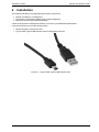
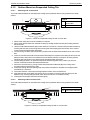
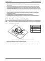
1
VESDA VLQ
Product Guide
VLQ-100
February 2014
Document: 26104_03
Part Number: 30320
VESDA by Xtralis
VESDA VLQ Product Guide
Intellectual Property and Copyright
This document includes registered and unregistered trademarks. All trademarks displayed are the trademarks of
their respective owners. Your use of this document does not constitute or create a licence or any other right to use
the name and/or trademark and/or label.
This document is subject to copyright owned by Xtralis AG (“Xtralis”). You agree not to copy, communicate to the
public, adapt, distribute, transfer, sell, modify or publish any contents of this document without the express prior
written consent of Xtralis.
Disclaimer
The contents of this document is provided on an “as is” basis. No representation or warranty (either express or
implied) is made as to the completeness, accuracy or reliability of the contents of this document. The manufacturer
reserves the right to change designs or specifications without obligation and without further notice. Except as
otherwise provided, all warranties, express or implied, including without limitation any implied warranties of
merchantability and fitness for a particular purpose are expressly excluded.
General Warning
This product must only be installed, configured and used strictly in accordance with the General Terms and
Conditions, User Manual and product documents available from Xtralis. All proper health and safety precautions
must be taken during the installation, commissioning and maintenance of the product. The system should not be
connected to a power source until all the components have been installed. Proper safety precautions must be taken
during tests and maintenance of the products when these are still connected to the power source. Failure to do so
or tampering with the electronics inside the products can result in an electric shock causing injury or death and may
cause equipment damage. Xtralis is not responsible and cannot be held accountable for any liability that may arise
due to improper use of the equipment and/or failure to take proper precautions. Only persons trained through an
Xtralis accredited training course can install, test and maintain the system.
Liability
You agree to install, configure and use the products strictly in accordance with the User Manual and product
documents available from Xtralis.
Xtralis is not liable to you or any other person for incidental, indirect, or consequential loss, expense or damages of
any kind including without limitation, loss of business, loss of profits or loss of data arising out of your use of the
products. Without limiting this general disclaimer the following specific warnings and disclaimers also apply:
Fitness for Purpose
You agree that you have been provided with a reasonable opportunity to appraise the products and have made
your own independent assessment of the fitness or suitability of the products for your purpose. You acknowledge
that you have not relied on any oral or written information, representation or advice given by or on behalf of Xtralis
or its representatives.
Total Liability
To the fullest extent permitted by law that any limitation or exclusion cannot apply, the total liability of Xtralis in
relation to the products is limited to:
1. in the case of services, the cost of having the services supplied again; or
2. in the case of goods, the lowest cost of replacing the goods, acquiring equivalent goods or having the goods
repaired.
Indemnification
You agree to fully indemnify and hold Xtralis harmless for any claim, cost, demand or damage (including legal costs
on a full indemnity basis) incurred or which may be incurred arising from your use of the products.
Miscellaneous
If any provision outlined above is found to be invalid or unenforceable by a court of law, such invalidity or
unenforceability will not affect the remainder which will continue in full force and effect. All rights not expressly
granted are reserved.
www.xtralis.com
i
VESDA VLQ Product Guide
VESDA by Xtralis
Scope
The VESDA VLQ Product Guide provides a comprehensive description of the VLQ detector.
This guide introduces the VESDA VLQ features, technical specifications and gives an understanding of its
components and their function. You will also find instructions on installing, cabling and powering up the
detector.
This guide is for anyone involved with the design, maintenance and purchasing of a VESDA VLQ system. It is
assumed that anyone using this product has the knowledge and appropriate certification from local fire and
electrical authorities.
Document Conventions
The following typographic conventions are used in this document:
Convention Description
Bold
Used to denote: emphasis.
Used for names of menus, menu options, toolbar buttons
Italics
Used to denote: references to other parts of this document or other
documents. Used for the result of an action.
The following icons are used in this document:
Convention Description
Caution: This icon is used to indicate that there is a danger to
equipment. The danger could be loss of data, physical damage, or
permanent corruption of configuration details.
Warning: This icon is used to indicate that there is a danger of electric
shock. This may lead to death or permanent injury.
Warning: This icon is used to indicate that there is a danger of inhaling
dangerous substances. This may lead to death or permanent injury.
Contact Us
UK and Europe
+44 1442 242 330
D-A-CH
+49 431 23284 1
The Americas
+1 781 740 2223
Middle East
+962 6 588 5622
Asia
+86 21 5240 0077
Australia and New Zealand
+61 3 9936 7000
www.xtralis.com
ii
www.xtralis.com
VESDA by Xtralis
VESDA VLQ Product Guide
Codes and Standards Information for Air Sampling Smoke Detection
We strongly recommend that this document is read in conjunction with the appropriate local codes and standards
for smoke detection and electrical connections. This document contains generic product information and some
sections may not comply with all local codes and standards. In these cases, the local codes and standards must
take precedence. The information below was correct at time of printing but may now be out of date, check with your
local codes, standards and listings for the current restrictions.
FCC Compliance Statement
This equipment has been tested and found to comply with the limits for a Class B digital device, pursuant to part 15
of the FCC Rules. These limits are designed to provide reasonable protection against harmful interference in a
residential installation. This equipment generates, uses and can radiate radio frequency energy and, if not installed
and used in accordance with the instruction, may cause harmful interference to radio communications. However,
there is no guarantee that interference will not occur in a particular installation. If this equipment does cause
harmful interference to radio or television reception, the user is encouraged to try to correct the interference by one
or more of the following measures; re-orientate or relocate the receiving antenna, increase the separation between
the equipment and receiver, connect the equipment to a power outlet which is on a different power circuit to the
receiver or consult the dealer or an experienced radio/television technician for help.
FDA
This Xtralis product incorporates a laser device and is classified as a Class 1 laser product that complies with FDA
regulations 21 CFR 1040.10. The laser is housed in a sealed detector chamber and contains no serviceable parts.
The laser emits invisible light and can be hazardous if viewed with the naked eye. Under no circumstances should
the detector chamber be opened.
The laser chamber is identified by the label shown below:
DO NOT OPEN
NO SERVICEABLE
PARTS
DANGER
NE PAS OUVRIR
DISPOSITIFS/PIECES
NON ECHANGEABLES
Laser Radiation when Open
AVOID DIRECT EXPOSURE TO BEAM
Rayonnement Laser en cas d’ouverture
EVITEZ TOUTE EXPOSITION DIRECTE AU FAISCEAU
Product Listings
l
l
l
l
UL
ULC
VNIPPO
EN 54-20 and other agencies (pending)
Document: 26104_03
Part Number: 30320
www.xtralis.com
iii
VESDA VLQ Product Guide
VESDA by Xtralis
This page is intentionally left blank.
iv
www.xtralis.com
VESDA by Xtralis
VESDA VLQ Product Guide
Table of Contents
1
2
Introduction
3
1.1
Features
4
Product Information
5
2.1
2.2
2.3
2.4
3
4
5
6
7
8
9
How it Works
Detector Overview
Specifications
Dimensions
5
6
9
10
Air Sampling Pipe Network
11
3.1
3.2
3.3
3.4
11
11
11
12
Installation Considerations
Pipe Inlets
Exhaust Air
Air Sampling Configurations
Installation
15
4.1
4.2
4.3
4.4
4.5
4.6
16
22
25
26
27
27
Mounting
Wiring
Specify Backup Battery for Power Supply
Installation Checklist
Powering Up
Preliminary System Check
Configuration
29
5.1
5.2
5.3
29
29
30
Logging on using the Display Panel
Setting the time using the Display Panel
DIP Switch Configuration
Commissioning
31
6.1
6.2
31
31
AutoLearn Smoke
Commissioning Smoke Test
Xtralis QSC Software
33
7.1
7.2
7.3
7.4
33
33
34
35
Installation
Functions
Configuration
Device Information
Maintenance
37
8.1
37
Replacing the Filter
Troubleshooting
41
9.1
41
Fault Codes
www.xtralis.com
1
VESDA VLQ Product Guide
VESDA by Xtralis
This page is intentionally left blank.
2
www.xtralis.com
VESDA by Xtralis
1
VESDA VLQ Product Guide
Introduction
The VESDA VLQ is an Aspirating Smoke Detector (ASD) that provides very early warning of fire conditions
by drawing air samples through sampling holes located in an air sampling pipe network.
The VESDA VLQ detector is specifically designed to cater for small areas up to 100 m² (1000 ft²). VESDA
VLQ is suited to several applications, including but not limited to:
l
l
l
l
l
l
l
l
l
l
l
l
l
l
l
l
l
Telecommunications land line remote offices
Base station controllers (BSC)
Base transceiver stations (BTS)
Server rooms
Datacenter containers
IT/equipment cabinets
Controlled environmental vaults (CEV)
Semi-conductor tools
Modular laboratories
Anechoic chambers
Flight simulators
Generator enclosures
Signaling huts
Pump houses
Ammunitions holding areas
Hyperbaric chambers
Barracks self-contained units
Connection to the detector using Xtralis QSC software is available via the USB interface.
Figure 1-1: VESDA VLQ
The detector contains dry-contact relays which allow connectivity to fire warning and fire suppression release
systems, and integration into a building management system (BMS).
www.xtralis.com
3
VESDA VLQ Product Guide
1.1
VESDA by Xtralis
Features
The VESDA VLQ detector provides the following features:
l
l
l
l
l
l
l
l
l
l
l
l
l
l
l
l
4
Laser-based absolute smoke detection
Clean air barriers for optics protection
Up to 100 m² (1000 ft²)coverage
Up to 2 x 6m (2 x 20ft) pipes (straight), up to 2 x 9m (2 x 30ft) pipes (branched)
2 or 4 VEWFD / EWFD (NFPA76), or 2 or 4 Class A / Class B (EN 54-20) sample holes
Metric/Imperial pipe inlets
Pre-alarm, Alarm and Fault Relays
5 LEDs: Pre-alarm, Fire-alarm, Fault, Power, Filter replacement
Monitored on-board filter
AutoLearn Smoke
General Purpose Input (GPI)
IP30 enclosure
Xtralis QSC software support
USB for direct PC connection
Event log
Low power consumption
www.xtralis.com
VESDA by Xtralis
2
VESDA VLQ Product Guide
Product Information
2.1
How it Works
The VESDA VLQ detector continually samples air from the protected environment via two pipe inlets for the
sampling pipes on each side of the pipe inlets (A1, A2). Upon entering the detector, the air passes through
respective inlet manifolds (B1, B2) and the aspirators (C1, C2). The sampled air then enters the filter (D)
where the majority is exhausted out through filter exhaust (I2) and a portion from each inlet is separated into
two pathways, one pathway enters as clean air (E1,E2) and the other pathway enters as sampled air (F1,F2)
into the detection chamber (G). Sampled air is used for smoke detection and the clean air used for optics
protection. After smoke detection the air is exhausted out of the chamber exhaust (I1). Flow measurement is
performed at the chamber exhaust (H).
Legend
A1
A2
B1
B2
C1
C2
A
Pipe Inlets
B
Manifolds
C
Aspirators
D
Filter
E
Clean Air
F
Sample Air
G Detection Chamber
H
Flow Sensor
I
Exhaust
D
E1
F1
E2
F2
G
H
I2
I1
Figure 2-1: Air Path
www.xtralis.com
5
VESDA VLQ Product Guide
2.2
VESDA by Xtralis
Detector Overview
The VESDA VLQ detector is a lightweight unit designed to be ceiling or wall mounted and operates with a
simple sampling pipe network. The detector unit features two sampling pipe inlets, unobtrusive exhaust vents,
a simple control panel and display, and a buzzer to provide audio notifications.
A USB port, described below in Section 2.2.3, provides the ability to interface with a computer, which allows
configuration with the Xtralis QSC software. Configuration DIP switches and wiring terminals are located
beneath the detector and are accessible by removing the detector base..
Legend
B
A
A
Sampling Pipe Inlets
B
Exhaust Vents
C
Front Panel
A
C
Figure 2-2: VESDA VLQ Detector Overview
2.2.1
Front Panel
The VESDA VLQ front panel contains a series of indicators and buttons. These are described below.
88
B
C
A
D
E
Figure 2-3: VESDA VLQ Front Panel and Status LEDs
Indicators
The VESDA VLQ detector provides information via a series of Status LEDs.
Table 2-1: LED Indicators
LED
6
Color
Description
A Power
Green
The Power LED illuminates when the detector is
powered up.
B Filter Replacement
Yellow
The Filter Replacement LED is lit when the filter is due
for replacement.
C Fault
Yellow
The Fault LED is lit when a fault condition is detected.
D Pre-Alarm
Red
The Pre-Alarm LED is lit when the Pre-Alarm threshold
is reached.
E Fire-Alarm
Red
The Fire LED is lit when the Fire threshold is reached.
www.xtralis.com
VESDA by Xtralis
VESDA VLQ Product Guide
Buttons
The VESDA VLQ detector provides accessibility to a range of functions via a set of control buttons.
Table 2-2: Control Buttons
Button
Reset / Silence
Description
Resetting the detector unlatches all latched alarms and
faults, returns relays to their normal state and clears the
active event list.
Silencing silences the buzzer for the current fault.
l
l
l
To reset the detector, press this button once, 'rs' is
displayed on the panel.
To silence the buzzer, press and hold this button till
"SI" is displayed on the panel (5 to 10 seconds). SI is
displayed alternately with the highest priority fault
code. The buzzer will remain silent unless another fault
is reported.
To take detector out of Silence mode, press this button
once while detector is displaying "SI".
While the filter is removed, pressing the Reset / Silence
button once will reset the filter use percentage value.
Disable / Standby
Disabling the detector disables all relay outputs with the
exception of the fault relay. The aspirator remains active.
Standby shuts down the aspirator and puts the detector
standby mode. There is no smoke detection during standby,
and the fault relay is activated.
l
l
l
To disable the detector, press this button once.
To re-enable the unit, press the button while "db" is
displayed on the panel.
To place the detector in standby mode, press and hold
this button until "Sb" is displayed on the panel (5 to 10
seconds). To take detector out of standby mode, push
and hold this button when "Sb" is displayed on the
panel (5 to 10 seconds).
Note:
Test
Two Test modes are available:
l
l
Lamp and Buzzer Test: Press this button to ensure
that all LEDs, display segments and buzzer operate
correctly. "Lt" is displayed momentarily when the
button is pressed.
Alarm and Fault Test: Press and hold this button until
"At" is displayed on the front panel (5 to 10 seconds). It
activates alarm and fault relays. To stop the test press
and hold this button when "At" is displayed on the
panel.
Note:
www.xtralis.com
You must be logged on to the detector through
front panel to use this button. Refer to Section 5.1
for further information.
You must be logged on to the detector through
front panel to use this button. Refer to Section 5.1
for further information.
7
VESDA VLQ Product Guide
VESDA by Xtralis
Table 2-2: Control Buttons (continued...)
Button
Normalize Airflow /
AutoLearn Smoke
Description
Airflow Normalization sets the reference point for airflow
thresholds based on ambient operating conditions.
AutoLearn Smoke sets the alarm thresholds based on the
environmental conditions.
l
l
Press this button once to start the flow normalization,
'no' is displayed on the panel. Normalization takes
between 5 to 10 minutes. To cancel normalization
press this button while 'no' is displayed.
To start the AutoLearn smoke press and hold this
button till "AL" is displayed on the panel. AutoLearn
takes 15 minutes to complete when started from the
panel. To cancel the AutoLearn press and hold this
button when "AL" is displayed.
Notes:
l
l
l
2.2.2
AutoLearn Smoke thresholds are volatile, therefore if
thresholds are set using AutoLearn smoke then it must
be run each time the detector is powered up.
AutoLearn Smoke over-rides the DIP switch settings
within the smoke threshold range. Refer to Section 5.3
for further information.
You must be logged on to the detector through the front
panel to use this button. Refer to Section 5.1 for further
information.
Buzzer
The buzzer will sound under the following conditions:
l
l
l
l
l
During power up self testing.
When a Pre-Alarm is raised, the buzzer will alternate between on and off until the detector is silenced or
the smoke is no longer present.
When a Fire alarm is raised, the buzzer will beep continuously until the detector is silenced or the smoke
is no longer present.
When a Fault is detected, the buzzer will alternate between on and off until the detector is silenced or the
fault condition is corrected.
During a manually initiated system test.
2.2.3
USB Port
Detector configuration can be performed using the Xtralis QSC software installed on a computer connected to
the detector via the USB port. The USB port is located on the outside of the detector, beneath the shroud. It is
necessary to remove the rubber grommet in order to access this port.
Figure 2-4: USB Port
8
www.xtralis.com
VESDA by Xtralis
2.3
VESDA VLQ Product Guide
Specifications
Table 2-3: VLQ Detector Specifications
Specification
Value
Supply Voltage
24 VDC nominal (18 to 30 VDC), externally supplied from UL1481
/ EN54-4 listed power supply (as appropriate to meet local
codes). Ensure that the power supply is installed in accordance
with local electrical codes.
Current Consumption
170 mA (quiescent), 190 mA (alarm)
Dimensions
260 mm x 228 mm x 110 mm (10.24in x 8.98in x 4.35in)
Weight
1.2 Kg (2.65 lbs)
Operating Conditions
Temperature:
(To operate the VESDA VLQ detector outside
these parameters please contact your
nearest Xtralis Office.)
l
l
Tested to: -10°C to 55°C (14°F to 131°F) *
Recommended Ambient: 0°C to 39°C (32°F to 103°F)
Humidity:
l
Sampling Pipe Network
0-95% RH, non-condensing
Pipe Length:
l
l
Linear: Up to 2 x 6 m (2 x 20 ft.)
Branched: Up to 2 x 9 m (2 x 30 ft.)
Sampling Holes:
l
2 or 4 (1 or 2 per pipe)
Refer to Section 3.4 on page 12 for further information.
Pipe Size
Relays
Accepts both metric and American standard pipe sizes:
l Metric: 25 mm (1.05 in.)
l American Pipe: IPS 21 mm (¾ in.)
l
l
l
l
3 relays. Pre-Alarm, Fire and Fault
Contacts rated 2A @ 30 VDC
Programmable to latch or non-latch states
Programmable 0 - 60 sec delay for each relay
IP Rating
IP30
Mounting
Surface or flush mounting with optional mounting brackets.
Cable Access
l
l
Two cabling inlet points from top
Side entry through removable partition
Cable Termination
Screw terminal blocks (0.2-2.5 sq mm, 30-12 AWG)
PC Connection
USB (Type 2)
Sensitivity Range
0.005% - 3% obs/m (0.0015% - 0.915% obs/ft)
Threshold Setting Range
l
l
Fire Alarm: 0.15%/m - 3%/m (0.046%/ft - 0.915%/ft)
Pre-Alarm: 0.1%/m - 1.5%/m (0.03%/ft - 0.457%/ft)
* Product UL listed between 0° to 39°C (32° F to 103° F)
Table 2-4: Software Features
Specification
Value
Event Log
Up to 1,000 events
www.xtralis.com
9
VESDA VLQ Product Guide
VESDA by Xtralis
Table 2-4: Software Features (continued...)
Specification
Value
AutoLearn Smoke
l
l
l
Minimum: 15 minutes
Maximum: 2 Hours (through Xtralis QSC)
Recommended minimum period: 1 hour
Thresholds are automatically changed from the previously set
values to the updated values after the AutoLearn process has
completed. AutoLearn Smoke over-rides the DIP switch settings
within the smoke threshold range.
Maintenance Aids
l
l
2.3.1
Event log
Smoke log
Ordering Information
Table 2-5: Ordering Information
Part Number
Description
VLQ-100
Detector
VSP-890
Surface Mount Kit
VSP-891
Flush Mount Kit
VSP-892
Replacement Filter
VSP-892-20
Replacement Filter - 20 pieces
VSP-893
Pipe Kit (Metric)
VSP-893-US
Pipe Kit (Imperial)
2.4
Dimensions
13 mm max
[ 0.50 in max]
26.8 mm
[ 1.05 in ]
56.2 mm
[ 2.21 in ]
63.2 mm
[ 2.49 in ]
110 mm
[ 4.35 in ]
228 mm
[ 8.98 in ]
114 mm
[ 4.49 in ]
260 mm
[ 10.24 in ]
Figure 2-5: Detector Dimensions
10
www.xtralis.com
VESDA by Xtralis
3
VESDA VLQ Product Guide
Air Sampling Pipe Network
The detector uses two linear pipes of up to 6 m (20 ft) or two branched pipes of up to 9 m (30ft) to cover a
maximum of 100 m² (1000 ft²). Short pipes can be used to suit the installation.
3.1
Installation Considerations
The following points should be considered when installing sampling pipe:
l
l
l
l
l
l
l
l
l
l
Minimize flexing in sampling pipes by supporting the pipe every 1.5 m (5 ft) or less, or at a distance
described in local codes and standards.
Sampling pipe fits firmly into the tapered detector port, DO NOT glue this connection.
Allow sufficient movement at the detector to permit pipe removal for maintenance.
Pipe ends must be made smooth for bonding.
Sampling holes must be drilled in line and perpendicular to the pipe.
Sample holes must be clear of rough edges and debris.
Ensure that all sampling holes are from within a single space (not physically different areas separated by
walls).
Ensure that there is no pressure differential between sampling holes and exhaust ports.
Pipes are free of debris.
All joints must be glued except the pipes entering the detector.
Notes:
l
l
Sampling holes should face into the direction of airflow, or point downwards in static airflow situations.
For return air sampling refer to the notes in Section 3.4 on page 12.
For code-specific information, see Codes and Standards Information for Air Sampling Smoke Detection
on page iii.
3.2
Pipe Inlets
The VESDA VLQ detector supports two sampling pipes. Both pipes must be connected for proper detector
operation.
The air inlet ports are tapered such that they accommodate both 25 mm (1 in) or IPS ¾ inch (1.05 in outer
diameter) pipes. Each air inlet port allows maximum insertion of the sampling pipe to a depth of 15 mm (0.60
in).
While connecting the detector to the pipe network:
l
l
Square off and de-burr the end of the sampling air pipes, ensuring the pipes are free from debris.
Insert the pipes into the pipe inlet(s) ensuring a firm fit.
Note:
DO NOT glue the pipes to the pipe inlets.
3.3
Exhaust Air
Air is expelled from the detector via the filter and after the detection chamber into the area where the detector
is located. Refer to Figure 2-2 on page 6.
There should be no pressure differential between the sampling holes and the exhaust ports.
www.xtralis.com
11
VESDA VLQ Product Guide
3.4
VESDA by Xtralis
Air Sampling Configurations
Both inlets must be fitted with pipes with 1 or 2 holes and the configuration must comply to the rules in Table 3-1 below. Table 3-1: Pipe and Sampling Hole Rules
Notes:
Description
1 hole per
pipe
2 holes per Combined
pipe
Inlet
Minimum pipe length per inlet
15 cm (6 in)
15 cm (6 in)
n/a
Maximum linear pipe length per inlet /
combined inlet from detector to furthest
sampling hole
6 m (20 ft)
6 m (20 ft)
6 m (20 ft)
Maximum branched pipe length per inlet
(total)
n/a
9 m (30 ft)
n/a
Maximum distance in branched pipe from
detector to furthest sampling hole
n/a
6 m (20 ft)
n/a
Furthest sampling hole distance from the
detector
6 m (20 ft)
6 m (20 ft)
6 m (20 ft)
Hole sizes per pipe / combined inlet pipe
1 x 6.5 mm
(1/4")
2 x 4.5 mm
(11/64")
2 x 6.5 mm
(1/4") or
4 x 4.5 mm
(11/64")
Maximum capillary length
30 cm (1 ft)
30 cm (1 ft)
30 cm (1 ft)
12
l
l
l
l
l
l
l
l
Ensure that all sampling holes are from within a single space (not physically
separated by walls).
Ensure that there is no pressure differential between sampling holes and the
exhaust port.
Ensure that the number of bends does not exceed four (4) per inlet and per
branch.
Do not use a single VLQ to perform ceiling and return air grille detection.
For return air grille detection, the pipe can be routed to the return air grille whilst
the detector is installed away from the return air grille. The sampling holes must
be oriented 30° to the incoming airflow direction.
Ensure that the air sampling configuration complies to local codes and
standards.
Ensure that the rules in Table 3-1 are followed when a single hole per inlet or two
holes per inlet are used.
When the air sampling pipes are unbalanced, for example configurations 2A, 3B,
4C shown in Table 3-2 below, smoke entering the holes closer to the detector
will trigger an alarm earlier than smoke entering the furthest holes.
www.xtralis.com
VESDA by Xtralis
VESDA VLQ Product Guide
Table 3-2: Air Sampling Configurations
No. of
Sampling
Locations
Example Detector Configurations
1
Description
These are the recommended configurations for small protected
areas where a single sampling location is required.
A
l
B
l
2
A
B
l
EN 54-20
Class-A
EN 54-20
Class-B
EN 54-20
Class-C
0.4
0.8
3
(0.125)
(0.25)
(0.937)
0.2
0.4
3
(0.063 )
(0.125)
(0.937)
0.15
0.3
2
(0.046)
(0.094)
(0.625)
0.15
0.3
2
(0.046)
(0.094)
(0.625)
A: 2 x 4.5mm (11/64") holes per inlet or 1 x 6.5mm (1/4")
hole per inlet.
B: 4 x 4.5mm (11/64") or 2 x 6.5mm (1/4") holes close to
each other for a combined inlet configuration.
These are the recommended configurations for small protected
areas where two sampling locations are required.
l
Fire-Alarm Threshold Setting Upper
Limit - %/m (%/ft)
NFPA76
NFPA76
NFPA76
VEWFD /
EWFD /
SFD /
A, B: 2 x 4.5mm (11/64") holes per inlet or 1 x 6.5mm (1/4")
hole per inlet.
C: 2 x 6.5mm (1/4") holes
C
3
A
B
These are the recommended configurations for protected areas
where three sampling locations are required.
l
4
A
2 x 4.5mm (in) holes per inlet.
These are the recommended configurations to maximize the area
coverage with four sampling locations.
l
2 x 4.5mm (in) holes per inlet.
B
C
www.xtralis.com
13
VESDA VLQ Product Guide
VESDA by Xtralis
This page is intentionally left blank.
14
www.xtralis.com
VESDA by Xtralis
4
VESDA VLQ Product Guide
Installation
The VESDA VLQ detector is shipped with the following components:
l
l
l
VESDA VLQ detector, including base
Flush Mount or Surface Mount bracket kits (ordered separately)
Stub pipes and end caps (ordered separately)
Check all components for damage and refer any concerns to your authorized representative.
It may be necessary to procure the following items:
l
l
Generic third party wiring junction box
Type A to Mini Type B USB Interface Lead for configuration purposes.
Figure 4-1: Type A to Mini Type B USB Interface Lead
www.xtralis.com
15
VESDA VLQ Product Guide
4.1
VESDA by Xtralis
Mounting
Depending on the type of surface, the VESDA VLQ detector can be installed in different ways to suit
environmental, aesthetic and local code requirements. There are several mounting techniques described in
this section to suit different mounting surfaces
The detector base is used in all mounting techniques in conjunction with either the surface mount bracket or
flush mount bracket to secure the detector to the mounting surface.
Detector Base
Surface Mount Bracket
Flush Mount Bracket
Figure 4-2: Detector base and mounting brackets
When the detector is attached to the detector base, the sampling pipes on the detector must be aligned with
the sampling pipe markers on the base. Push the detector into the base on 45 degree counter-clockwise
rotation, then rotate 45 degrees clockwise to lock into place.
Figure 4-3: Fit detector to base and rotate clockwise
4.1.1
Surface Mount on Hard Ceiling / Wall
4.1.1.1
Mounting with Junction Box
This mounting technique is used where conduit and cable entry is required on the surface of the wall or ceiling.
Legend
B
A
C
A
Generic third party
Junction Box
B
Surface Mount Bracket
C
Electrical Conduit
Figure 4-4: Ceiling mounted with Junction Box
16
www.xtralis.com
VESDA by Xtralis
VESDA VLQ Product Guide
1. Secure the Junction Box (A) to the hard surface with appropriate fasteners.
2. Connect wiring conduit (C) to Junction Box and pass the wires through.
3. Remove the detector base from the detector body by holding the detector body and rotating the base
anti-clockwise.
4. Pass wires through the detector base and screw the detector base to the Surface Mount Bracket (B).
5. Screw the surface mount bracket to the junction box and pass the wires through its holes, ensuring that
the sampling pipe inlet arrows on the surface mount bracket are appropriately positioned.
6. Feed wires through the wire retaining strip on the base of the detector and attach to the appropriate
terminal block connectors.
7. Fit the terminal bock connectors to the appropriate sockets on the terminal block.
8. Align detector body to the base so that there is room to rotate it clockwise, ensuring that pipe inlets
match the arrows shown on the detector body.
9. Insert pipes into the pipe inlets and seat them tightly.
4.1.1.2
Mounting without Junction Box
This mounting technique is used where concealed cable entry is possible.
Figure 4-5: Ceiling mounted with no Junction Box
1. Remove the detector base from detector body by holding the detector body and rotating the base anticlockwise.
2. Secure the detector base to the hard surface with appropriate fasteners, ensuring that the sampling pipe
inlet arrows on the detector base are appropriately positioned.
3. Remove the appropriate number of side teeth above the sloped front panel cover (Figure 4-6) to allow
wires to pass through.
4. Feed wires through the wire retaining strip on the base of the detector and attach to the appropriate
terminal block connectors.
5. Fit the terminal bock connectors to the appropriate sockets on the terminal block.
6. Align detector body to the base so that there is room to rotate it clockwise, ensuring that pipe inlets
match the arrows shown on the detector body.
7. Insert pipes into the pipe inlets and seat them tightly.
Legend
A
Remove Teeth
A
Figure 4-6: Remove teeth to provide cabling access
www.xtralis.com
17
VESDA VLQ Product Guide
VESDA by Xtralis
4.1.2
Surface Mount on Suspended Ceiling Tile
4.1.2.1
Mounting with Junction Box
The Surface Mount Bracket is used behind the ceiling tile to spread the detector fixing load across a weak
surface.
A
B
Legend
A
Generic third party
Junction Box
B
Surface Mount Bracket
Figure 4-7: Mount on suspended Ceiling Tile with Junction Box
1. Remove the ceiling tile on which installation is required.
2. Remove the detector base from the detector body by holding the detector body and rotating the base
anti-clockwise
3. Use the Surface Mount Bracket (B) to mark and then cut holes for connection with the detector base (3
screws) and the holes for the wiring inlets ensuring that the sampling pipe inlet arrows on the surface
mount bracket are appropriately positioned.
4. Connect wiring conduit to the Junction Box (A) and screw the Surface Mount Bracket into the Junction
Box.
5. Insert Junction Box and surface mount bracket assembly from top side of the ceiling tile and screw the
detector base to the surface mount bracket from the bottom side of the ceiling tile, ensuring that the
sampling pipe inlet arrows on the detector body are appropriately positioned.
6. Put the ceiling tile back in its position and pass the wires through the wiring conduit, junction box,
surface mount bracket holes and detector base holes.
7. Secure the Junction Box (A), wiring conduit and Surface Mount Bracket (B) in the ceiling void in
accordance with local electrical codes.
8. Feed wires through the wire retaining strip on the base of the detector and attach to the appropriate
terminal block connectors.
9. Fit the terminal bock connectors to the appropriate sockets on the terminal block.
10. Align detector body to the base so that there is room to rotate it clockwise and then slide it into the
detector body, ensuring that pipe inlets match the arrows shown on the detector body.
11. Insert pipes into the pipe inlets and seal them tightly.
4.1.2.2
Mounting without Junction Box
The Surface Mount Bracket is used behind the ceiling tile to spread the detector fixing load across a weak
surface.
A
Legend
A
Surface Mount Bracket
Figure 4-8: Mount on suspended Ceiling Tile with no Junction Box
18
www.xtralis.com
VESDA by Xtralis
VESDA VLQ Product Guide
1. Remove the ceiling tile on which installation is required.
2. Remove the detector base from the detector body by holding the detector body and rotating the base
anti-clockwise.
3. Use Surface Mount Bracket (A) to drill three mounting holes and two wiring holes into the ceiling tile,
ensuring that the sampling pipe inlet arrows on the surface mount bracket are appropriately positioned.
4. Insert Surface Mount Bracket from top side of the ceiling tile and screw the detector base into it from the
bottom side of the ceiling tile.
5. Put the ceiling tile back in its position and pass the wires through the surface mount bracket and detector
base holes.
6. Secure the surface mount bracket in the ceiling void in accordance with local electrical codes.
7. Feed wires through the wire retaining strip on the base of the detector and attach to the appropriate
terminal block connectors.
8. Fit the terminal bock connectors to the appropriate sockets on the terminal block.
9. Align detector body to the base so that there is room to rotate it clockwise, ensuring that pipe inlets
match the arrows shown on the detector body.
10. Insert pipes into the pipe inlets and seal them tightly.
4.1.3
Flush Mount on Suspended Ceiling Tile
Flush mounting places the sampling pipes inside the ceiling cavity and the detector body in the protected area.
Note:
4.1.3.1
There must be no significant pressure differential between the ceiling cavity and the protected area.
Mounting with Junction Box
Legend
A
C
A
Ceiling Tile
B
Flush Mount Bracket
C
Generic third party
Junction Box
D
Surface Mount Bracket
B
D
Figure 4-9: Flush Mount on suspended Ceiling Tile with Junction Box
1. Remove the ceiling tile (A) on which installation is required.
2. Use the Flush Mount Bracket (B) to cut the tile to pass the detector body and drill four holes for the
shroud screws.
3. Remove the Shroud (E), pipe inlet fascia (F) and snap-offs (G) from both pipe inlets (Figure 4-10).
www.xtralis.com
19
VESDA VLQ Product Guide
VESDA by Xtralis
Legend
E
E
Remove Shroud
F
Remove pipe-inlet
fascia
G
Remove snapoffs
H
Snapoffs removed
F
G
G
H
Figure 4-10: Remove shroud, pipe inlet fascia and snapoffs
4. Place the Flush Mount Bracket (B) from the top side of the tile and screw the Shroud (E), placed from the
bottom side of the ceiling tile.
5. Remove the detector base from the detector body by holding the detector body and rotating the base anti
clockwise.
6. Screw the Junction Box (C) to the Surface Mount Bracket (D) with appropriate fasteners.
7. Screw the Junction Box with Surface Mount Bracket to the Detector Base, then pass the wires from the
conduit through to the Junction Box (C), Surface Mount Bracket (D) and Detector Base. (Do not connect
conduit to the Junction Box yet.)
8. Feed wires through the wire retaining strip on the base of the detector and attach to the appropriate
terminal block connectors.
9. Fit the terminal bock connectors to the appropriate sockets on the terminal block.
10. Align detector base to the detector body so that there is room to rotate it anti-clockwise and then slide the
detector body into the detector base, ensuring that pipe inlets match the arrows shown on the detector
body.
11. Insert the detector body from the top side of the tile and snap fit to the Shroud (E).
12. Where applicable, reposition the ceiling tile (A).
13. Connect wiring conduit to the Junction Box (C).
14. Secure the Flush Mount Bracket (B) in the ceiling void in accordance with local electrical codes.
15. Insert pipes into the pipe inlets and seal them tightly. Use short capillary tubes (maximum 30 cm / 1 ft)
with appropriate sampling heads.
20
www.xtralis.com
VESDA by Xtralis
4.1.3.2
VESDA VLQ Product Guide
Mounting without Junction Box
Legend
A
A
Ceiling or Ceiling Tile
B
Flush Mount Bracket
C
Detector Base Holes
C
B
Figure 4-11: Flush Mount on suspended Ceiling Tile with no Junction Box
1. Follow steps 1 to 5 from the previous section.
2. Pass the wires through the detector base holes (C).
3. Feed wires through the wire retaining strip on the base of the detector and attach to the appropriate
terminal block connectors.
4. Fit the terminal bock connectors to the appropriate sockets on the terminal block.
5. Align detector base body to the detector body so that there is room to rotate it anti-clockwise, ensuring
that pipe inlets match the arrows shown on the detector body.
6. Support the flush mount bracket in the ceiling void in accordance with local electrical codes.
7. Insert pipes into the pipe inlets and seat them tightly. Use short capillary tubes (maximum 30cm/1ft) with
appropriate sampling heads.
www.xtralis.com
21
VESDA VLQ Product Guide
4.2
VESDA by Xtralis
Wiring
The terminal block connectors located on the underside of the VESDA VLQ detector will accept 0.2 - 2.5 mm²
or 30-12 AWG wire sizes.
4.2.1
Cabling Inlet
There are two cabling inlet ports. The ports are fitted with rubber grommets. They are not intended for wiring
conduit connections. System designs that use conduit must use the optional brackets and junction box.
4.2.2
Wiring Terminals
The wiring terminals are located beneath the detector (Figure 1-1), and are accessible when the detector has
been detached from the detector base.
POWER
FAULT
PRE-ALARM
ALARM
GPI
0V
+24V
NO
NC
COM
NO
COM
NO
NC
COM
+
Figure 4-12: Wiring Terminals
4.2.3
Relays
The relays interface to the Fire Alarm Control Panel (FACP) to communicate fault and alarm states. Refer to
Figure 4-12 above for the location of the relay terminals.
FAULT, PRE-ALARM and FIRE Relay Terminals
The FAULT relay is energized during normal operation while the PRE-ALARM and FIRE relays are only
energized when the respective alarm thresholds are exceeded after the configured time delay. The operation
of the relays are summarized in the following table.
Table 4-1: Fault and Fire Relay Operation
FAULT Relay
Normal Operation
(Energized)
22
Fault
or un-powered state
PRE-ALARM and FIRE Relay
Normal Operation
(De-energized)
Pre-Alarm or Fire
www.xtralis.com
VESDA by Xtralis
4.2.4
VESDA VLQ Product Guide
Monitored General Purpose Input (GPI)
The GPI is a programmable input which can be configured to initiate a number of different actions, including,
by default, a Remote Reset function. Refer to Section 7.3 on page 34 for GPI configuration options.
With monitored GPI, the detector monitors the GPI for open or short circuit faults when the GPI function is set
to any value.
When the GPI function parameter is set to PSU monitoring, the detector indicates an external equipment fault
condition by monitoring the line impedance. A 47K End of Line (EOL) resistor is supplied with the product and
must be assembled in parallel with the device to be monitored.
The EOL resistor provides a known termination to the external equipment, this allows the detector to identify
open or short circuits.
4.2.5
Typical Wiring for Monitored GPI for PSU Monitoring
The diagram below shows the correct way to configure power supply monitoring. It also shows where an End
Of Line (EOL) resistor is correctly installed.
Legend
C
B
A
D
A
External device (1 to N)
B
End of Line Resistor at device end of
wiring
C
GPI Pin 1
D
GPI Pin 2
Figure 4-13: Power Supply Connection Diagram
4.2.6
Typical Wiring to a Fire Alarm Control Panel (FACP)
The diagram below shows the correct way to wire VESDA detectors to a conventional fire alarm control panel
(FACP). It also shows where an End Of Line (EOL) resistor is correctly installed.
To next detector
or End of Line resistor (EOL)
Detector
Fire Panel (FACP)
Normally Closed (NC)
FIRE Common (C)
Normally Open (NO)
Input
Short = Fire
Open = Fault
Normally Closed (NC)
FAULT Common (C)
Normally Open (NO)
EOL
GPI
(Set to reset)
(NC)
Reset (C)
(NO)
Figure 4-14: Typical wiring to a fire panel with EOL
www.xtralis.com
23
VESDA VLQ Product Guide
4.2.7
VESDA by Xtralis
Wiring to an Addressable Loop Module
This wiring example is for wiring VESDA detectors to a typical Input/Output Loop module 3 inputs 1 output.
Note:
These are example drawings. Refer to the appropriate product manual for the exact wiring details of
the third party equipment.
Detector
3 Inputs 1 Output Loop Module
EOL*
Normally Closed (NC)
FIRE Common (C)
Normally Open (NO)
Fire Input
Short = Fire
Open = Wiring Fault
EOL*
Normally Closed (NC)
FAULT Common (C)
Normally Open (NO)
Fault Input
Short = Detector Fault
Open = Wiring Fault
EOL*
GPI
(Set to reset)
(NC)
Reset (C)
(NO)
*EOL: End of Line Resistor
To Next Detector
To FACP
Figure 4-15: Input/Output Loop Module with EOL
24
www.xtralis.com
VESDA by Xtralis
4.3
VESDA VLQ Product Guide
Specify Backup Battery for Power Supply
In the event of a mains power supply disruption, the VLQ detector runs on a backup battery connected to the
external power supply. The size of the battery is determined by:
l
l
l
l
l
local codes and standards
the total power required by the system
back up time required
allowance for reduction in capacity with age
expected temperature variations
Note:
It is recommended that batteries connected to the external power supply be inspected and changed
as per manufacturer’s specifications or as per local codes and standards.
To facilitate the calculation of the backup battery size, a Battery Calculation Sheet is included below.
Table 4-2: Calculating the size of backup battery
Equipment
Normal loads @ 24 V DC
Load mA
Detector
Other 24V Loads
Qty
Total
170
Full alarm load @ 24 V DC
Load mA
Qty
Total
190
Total
mA
Total
mA
X
Standby Hours
X
Alarm Hours
=
Standby Capacity
Alarm Capacity
Total Capacity =
Standby + Alarm
Divided by 1000 for
Standby Capacity
Multiply by battery
factor X1.25
www.xtralis.com
25
VESDA VLQ Product Guide
4.4
VESDA by Xtralis
Installation Checklist
Site Name
Address
Detector Serial Number(s) and Date of
Manufacture
Name of Installer
Signature
Date
Perform the following checks listed below to ensure that all the necessary items are completed before handing
over to a commissioning engineer.
Installation Checks
Yes No
Is the detector securely locked onto the mounting surface?
Are the sampling pipes firmly connected to the air inlet ports? Ensure that
the pipes are NOT glued into the detector.
Is power supply installed in accordance with local electrical codes and the
power wires been connected to the correct terminals inside the detector?
If required, has the GPI end of line resistor (EOL) been connected?
Have the alarm and fault signaling wires been terminated to the correct
terminals on the detector?
Is the air sampling pipework installed and checked as per the site plans?
26
www.xtralis.com
VESDA by Xtralis
4.5
VESDA VLQ Product Guide
Powering Up
After installing the detector it is necessary to power up the system. The power up sequence lasts
approximately two minutes.
The VESDA VLQ detector does not have a power switch, i.e it is hard wired to a 24 VDC supply and it is
assumed that the power supply has been installed as per manufacturers instructions in accordance with local
electrical codes.
If the system fails to power up, check all power wires are secured to their terminals and that the polarity is
correct.
On power up:
l
l
l
The Power LED illuminates and the detector runs a series of self-diagnostic and lamp tests.
If there is a fault, the Fault LED illuminates. To identify the fault, check the fault code on the display
panel or within the Xtralis QSC software.
The aspirator starts.
It is normal for the detector to display faults immediately after the first power up. Reset the detector using the
Xtralis QSC software or the reset button on the detector. This will unlatch the relays and turn off the Fault
LED. Any remaining faults will cause the Fault LED to illuminate again. Proceed with the preliminary system
check.
4.6
Preliminary System Check
A preliminary system check is required after installing the VESDA VLQ detector, before it is commissioned for
use. The check can be conducted by using buttons on the detector or by connecting to the detector using the
Xtralis QSC software. The preliminary systems check includes:
l
l
l
Normalizing the air flow. Activate the normalization process using the N button on the detector or by
using Xtralis QSC.
Conducting a basic smoke test.
Check interface to FACP, i.e. verify alarm and fault conditions.
www.xtralis.com
27
VESDA VLQ Product Guide
VESDA by Xtralis
This page is intentionally left blank.
28
www.xtralis.com
VESDA by Xtralis
5
VESDA VLQ Product Guide
Configuration
The VESDA VLQ detector is configured using the Xtralis QSC software or onboard DIP switches.
5.1
Logging on using the Display Panel
Prior to configuring or operating the detector using the display panel controls, it is necessary to log in to the
detector.
Login Sequence
To log out of the detector, use the same sequence. Once logged in, the detector shows "Ln" on the display.
Note:
When detector is logged-on from the front panel, it is not possible to log-on from Xtralis QSC, and
vice-versa.
5.2
Setting the time using the Display Panel
It is possible to set the time by the detector control panel or the Xtralis QSC software.
Setting the time using Xtralis QSC
1. Log onto the detector.
2. Press the Set Time button.
3. The current Hour, Minute, Second, Year, Month and Day settings are displayed in a pop-up window. Edit
as required then confirm the changes.
Setting the time using the Control Panel
1. Log on to the detector. Refer to Section 5.1 for further information.
2. Press and hold the Reset and Normalize buttons simultaneously for 5 seconds.
3. Set the hour by pressing the Test button to set the first digit, and the Disable button to set the second
digit. Press the Reset button when the correct value is on screen to advance.
4. Set the minute by pressing the Test button to set the first digit, and the Disable button to set the second
digit. Press the Reset button when the correct value is on screen to advance.
5. Set the second by pressing the Test button to set the first digit, and the Disable button to set the second
digit. Press the Reset button when the correct value is on screen to advance.
6. Set the year by pressing the Test button to set the first digit, and the Disable button to set the second
digit. Press the Reset button when the correct value is on screen to advance.
7. Set the month by pressing the Test button to set the first digit, and the Disable button to set the second
digit. Press the Reset button when the correct value is on screen to advance.
8. Set the day by pressing the Test button to set the first digit, and the Disable button to set the second
digit. Press the Reset button.
www.xtralis.com
29
VESDA VLQ Product Guide
5.3
VESDA by Xtralis
DIP Switch Configuration
OFF
ON
1 2 3 4 5 6 7 8
The VESDA VLQ provides a range of configuration options using an on-board DIP Switch bank.
Figure 5-1: DIP Switch Location
Table 5-1: DIP Switch Configuration
Switch Position
Purpose
Configuration
Options
Default Switch
Settings
OFF
OFF OFF 0.15%/m (0.046%/ft)
ON
OFF OFF 0.3%/m (0.091%/ft)
0.3%/m
(0.091%/ft)
OFF
ON
OFF 0.6%/m (0.18%/ft)
ON
ON
OFF 0.8%/m (0.28%/ft)
OFF
OFF
ON 1.0%/m (0.30%/ft)
ON
OFF
ON 1.5%/m (0.46%/ft)
OFF
ON
ON 2.0%/m (0.61%/ft)
ON
ON
ON 3.0%/m (0.91%/ft)
SW1 SW2 SW3
1,2,3
4
5
6
7
8
30
Set Fire Alarm Smoke
Threshold (Pre-alarm set
to 50% of Fire Alarm
automatically)
Set Fire Alarm Delays
Set Flow Delays
Set Fire Alarm latching
Set Fault latching
Set Flow Fault Limits
OFF
No Delay
ON
30s Delay
OFF
No Delay
ON
30s Delay
OFF
Fire Alarms not latched
ON
Fire Alarms latched
OFF
Faults not latched
ON
Faults latched
OFF
+/-20%
ON
+/-50%
OFF (No Delay)
OFF (No Delay)
ON (Latched)
ON (Latched)
ON (+/-50%)
www.xtralis.com
VESDA by Xtralis
6
VESDA VLQ Product Guide
Commissioning
The VESDA VLQ has been designed to simplify the commissioning process. The AutoLearn function allows
the unit to assess its environment and setup appropriate alarm thresholds.
The detector is monitored during commissioning using Xtralis QSC.
Once the VESDA VLQ detector has been commissioned, it will report alarms and faults according to the
parameters defined during installation.
Note:
Detectors should be commissioned with a smoke test.
Prior to commissioning the detector:
1. Check that the pipe network is clean and correctly fitted with all joints correctly glued (except where the
pipe enters the detector, which must not be glued).
2. Check that the power is connected and on. Let the detector run for around 5 minutes. Ignore the faults
during this time. Reset the detector after 5 minutes of operation.
3. Normalize the airflow. This takes approximately 5 minutes.
4. Reset the detector after normalization. It should now be running without faults.
It is important that the protected environment is representative of normal operating conditions during the
AutoLearn process.
For code-specific information, see Codes and Standards Information for Air Sampling Smoke Detection on
page iii.
6.1
AutoLearn Smoke
AutoLearn Smoke is initiated by using controls on the front panel or from within Xtralis QSC.
During the AutoLearn Smoke process, the detector determines the average smoke and peak smoke
obscuration levels and sets suitable alarm thresholds for the operating environment. This process will
minimize nuisance alarms due to normal environmental background variations.
During the learning cycle, if an alarm condition occurs, AutoLearn will not complete its cycle. In this situation
the user must restart the AutoLearn process. If AutoLearn is halted, the alarm thresholds will be left at the
previous settings.
Conditions experienced during learning are assumed to be representative of normal operating conditions.
The AutoLearn Smoke learning times range from 15 minutes to 2 hours.
Note:
AutoLearn Smoke thresholds are volatile, therefore if thresholds are set using AutoLearn smoke
then it must be run each time the detector is powered up.
6.2
Commissioning Smoke Test
It is recommended that a smoke test be carried out to verify the integrity of the pipe network, to demonstrate
that the system is working and to measure the transport time to the detector.`
This test involves introducing a smoke sample at the furthest sampling hole and then measuring the time
taken for the smoke to travel to the detector. Results are logged and compared to subsequent tests to note
variations of the system.
www.xtralis.com
31
VESDA VLQ Product Guide
VESDA by Xtralis
This page is intentionally left blank.
32
www.xtralis.com
VESDA by Xtralis
7
VESDA VLQ Product Guide
Xtralis QSC Software
Xtralis QSC is used for configuration and commissioning of the VESDA VLQ detector.
Buttons are green and change to pink when active, and only when logged on to VESDA VLQ are all the
buttons are visible.
7.1
Installation
1. Install the STM virtual COM Driver. Use the 32 bit (VCP_V1.x.x_Setup.exe) or 64 bit (VCP_V1.x.x_
Setup_x64.exe) installer as appropriate for your Windows operating system.
2. Extract the Xtralis QSC executable (QSC.exe) to a folder on your PC's hard drive but do not run it before
powering up the detector.
3. Connect a USB cable between the detector and the PC.
4. Apply power to the detector.
5. Launch Xtralis QSC. Xtralis QSC will report “Unable to open communication”.
6. Select Connection Parameters, and select the available COM port then OK.
7. Once connected, the detector time will be displayed at the bottom of the window and “Self_test” or
“Running” will be displayed in the status bar.
7.2
Functions
Table 7-1 below details Xtralis QSC commands (functions):
Table 7-1: Xtralis QSC Commands
Button / Function
Action
Logon / off
Default with Logon written.
When pressed turns to Pink and prompts user with another screen to login
to the VESDA VLQ unit. Press OK when Login screen pops up. Successful
logon makes other buttons visible where login is required to perform such
functions.
Reset
Resets alarms and faults when pressed and momentarily changes to Pink
and back to Green when reset is completed.
Silence
Silences the buzzer and changes to Pink.
Connection Parameters
Allows to choose the communication port, change to appropriate virtual com
port.
Reset Filter Use Percentage
VESDA VLQ stores smoke hours to determine filter usage and raises a
trouble to replace the filter when certain smoke hours limit is reached. This
button allows to reset the smoke hours when an expired filter is replaced
with a new filter. Filter must be removed from the unit to use this function.
Lamp Test
Allows to perform LED, Buzzer and display test once.
Alarm and Relay Test
Allows to perform fire and fault relay test, prompts the user with another
screen to test fire and fault relays. Alarm test simulates the smoke value to
generate an Alarm condition.
AutoLearn Smoke
Allows to start AutoLearn smoke feature. AutoLearn uses background
conditions to set appropriate thresholds.
Normalize Airflow
This button allows air flow normalization if the detector airflow is within the
acceptable range. Normalization takes approximately 5 minutes.
Disable On
Allows disabling of the detector, when disabled detector stops reporting
alarms on relays.
Standby On
Allows setting the detector to standby. The detector shuts down the
aspirator and stops airflow and smoke detection.
www.xtralis.com
33
VESDA VLQ Product Guide
VESDA by Xtralis
Table 7-1: Xtralis QSC Commands (continued...)
Button / Function
Action
Set Time
Allows setting of the detector time, chose set to PC time for this version
Get Event Log
Allows to log up to last 1000 events and stores in a CSV file (do not change
any timing on the right side up down button)
Get Smoke
Allows logging of smoke at between 1 and 60 second intervals and stores in
a CSV file, this is useful to determine minimum and maximum thresholds
settings during the fire tests if required. It is recommended that the smoke
interval is set to 10 seconds or greater. This is a live smoke data capture so
Xtralis QSC must be running during this function.
7.3
Configuration
Table 7-2 below details VLQ configuration items available in the Xtralis QSC software, under Device
Configuration.
Table 7-2: Configuration Items
Configuration Item
Description
Parameters / Range
Configure via Xtralis QSC
Allow configuration of the
detector from Xtralis QSC.
Enable/Disable
Unit
Set the units of smoke
Metric/Imperial
Fire Alarm Threshold
Set the threshold of Fire alarm
0.15%obs/m - 3%obs/m
(0.046%/ft - 0.915%/ft)
Pre-Alarm Threshold
Set the threshold of Pre-alarm
0.1%obs/m - 1.5%obs/m
(0.03%/ft - 0.457%/ft)
Alarm Delay
Configure delay of fire alarm
0, 30, 45 or 60 seconds
Alarm Latching
Allows to latch the fire relay
Enable/Disable
Fault Latching
Allows to latch the fault relay
Enable/Disable
Flow Fault Limit
Set the limit of flow fault
+/-20%, +/-50%
Fault Delay
Configure delay of fault
0, 30, 45 or 60 seconds
GPI Configuration
Configure the GPI action
l
l
l
l
Buzzer
34
Enable or disable buzzer
Reset
External Device (PSU)
Monitoring
Reset+Disable
Standby
Enable/Disable
www.xtralis.com
VESDA by Xtralis
7.4
VESDA VLQ Product Guide
Device Information
Table 7-3 below details information for the VLQ available in the Xtralis QSC software, under Device
Information.
Table 7-3: Device Information
Item
Description
Model
Displays model number
Serial Number
Displays serial number
Hardware Version
Displays hardware version
Software Version
Displays software version
Manufacturing Date
Displays manufacturing date
Temperature
Displays current temperature
Smoke Value
Displays current smoke value
Flow Value
Displays current raw flow value
Filter Used
Display filter use percentage value
www.xtralis.com
35
VESDA VLQ Product Guide
VESDA by Xtralis
This page is intentionally left blank.
36
www.xtralis.com
VESDA by Xtralis
8
VESDA VLQ Product Guide
Maintenance
To maintain the VESDA VLQ detector at its peak performance level, the recommended maintenance
schedule shown in Table 8-1 below should be followed.
Table 8-1: Recommended maintenance schedule for the VESDA VLQ detector
Maintenance Check
Quarterly
Six-monthly
Annual
Biennial
Power Supply and Battery
Check Pipes
Pipe Integrity Smoke Test
Check Pipe Flow
Clean Sampling Points
Flush Pipe Network
Replace Filter
8.1
Replacing the Filter
The detector reports a fault condition on the front panel and in the event log to indicate that the filter requires
replacement after the recommended period of time has elapsed, or filter use percentage limit reached,
whichever occurs first.
After removing the old filter and prior to inserting the new one, it is necessary to reset the filter used
percentage value. This can be done using the detector controls or from within Xtralis QSC.
Requirements
Philips head screwdriver
Filter Removal Procedure
1. Rotate cover 45° counter-clockwise and remove by lifting outwards (Figure 8-1).
B
A
Figure 8-1: Remove the Detector Cover
2. Release the filter:
l
Where the filter is secured with a retaining bracket: Remove screws (C) with a Philips head
screwdriver and lift out the filter retaining bracket (D) (Figure 8-2).
www.xtralis.com
37
VESDA VLQ Product Guide
VESDA by Xtralis
C
D
Figure 8-2: Remove filter retaining bracket
l
Where the filter is secured with retaining clips: Whilst holding the filter housing (B), loosen the
screws C and D with a Philips head screwdriver.turn the clips (E and F) outwards, away from the
magnets beneath them (Figure 8-3).
B
C
B
D
E
F
Figure 8-3: Loosen filter retaining screws
2. Lift the filter (G) out of the detector (Figure 8-4).
38
www.xtralis.com
VESDA by Xtralis
VESDA VLQ Product Guide
G
Figure 8-4: Remove Filter
Filter Insertion Procedure
1. With the filter removed from the detector, pressing Test and Disable button simultaneously displays filter
use percentage value. When a new filter is used reset the filter use percentage value. To do this, press
the Reset button on the front panel once, or use the Xtralis QSC software.
2. Tilt the new filter and align to the insertion guides (Figure 8-5) and lower filter into place.
Figure 8-5: Filter insertion
3. Reposition the retaining bracket, or for units with retaining clips, realign the clips with the magnets
(Figure 8-3, C and D).
4. Tighten the retaining screws using a Philips head screwdriver.
www.xtralis.com
39
VESDA VLQ Product Guide
VESDA by Xtralis
This page is intentionally left blank.
40
www.xtralis.com
VESDA by Xtralis
9
VESDA VLQ Product Guide
Troubleshooting
9.1
Fault Codes
Fault codes can be viewed on the LED display or by using the Xtralis QSC software.
l
l
l
Faults 01 though to 18 are hardware faults which require that the detector be replaced.
Faults 41 through to 50 are generally rectifiable with minimal user interaction.
To correct some faults, you may be prompted to log on to the detector. The login procedure is described
in Section 5.1 on page 29.
Table 9-1: Fault Codes
Fault Code Fault Type
01
Detector Hardware
Description
Possible Resolution
Self-test failed
Contact your authorized
service representative.
03
EEPROM fault
04
Calibration data EEPROM fault
05
Configuration fault
06
+12V fan power supply fault / main
board module fault
07
+5V power supply fault
08
3.3V power supply fault / main
board version fault
09
Laser control circuit fault
10
Smoke signal receive and
amplification circuit fault
11
Fans fault
12
Flow circuit fault
13
Ambient temperature circuit fault
14
Fault relay control circuit fault
15
Alarm relay control circuit fault
16
RTC fault
17
Chamber BG too high
18
Chamber BG too low
41
24V input power supply
fault
24V input voltage is lower than 18V Check PSU voltage across
or higher than 30V.
the 0V and +24V terminals
on the rear of the unit with
multimeter to ensure it is
constant and between 18 30V DC. Adjust or replace
the PSU as required.
42
Airflow Normalization
Failed
The detector has been unable to
establish a reference level for
normal airflow.
Check the sample holes,
pipe and connection to the
unit for obstruction and
integrity.
Make corrections as
required, restart the unit,
wait 10 minutes then
normalize again.
www.xtralis.com
41
VESDA VLQ Product Guide
VESDA by Xtralis
Table 9-1: Fault Codes (continued...)
Fault Code Fault Type
43
Autolearn Smoke Failed
Description
Possible Resolution
The detector has been unable to
Re-activate when area is
establish suitable alarm thresholds smoke-free, or set suitable
during Autolearn Smoke.
Pre-Alarm and Fire
thresholds manually using
the onboard DIP switches or
the Xtralis QSC software.
Refer to Section 5.3 on page
30 for further information
44
Filter Absent
Filter not fitted or fitted incorrectly
Check filter is fitted correctly
or insert new filter.
Refer to Section 8.1 on page
37 for further information.
45
Filter Replace
Filter life expired
Replace filter and reset filter
use percentage value.
Refer to Section 8.1 on page
37 for further information.
46
High Airflow
Airflow through one or both sample
pipes has exceeded the acceptable
high flow limit.
l
l
Check sample pipes
for damage, breaks.
Examine environment
for changes that may
affect airflow.
If a cause cannot be found,
normalize the detector.
47
Low Airflow
Airflow through one or both sample
pipes has exceeded the acceptable
low flow limit.
l
l
Check sampling holes
and pipe for obstruction
or partial blockage.
Examine environment
for changes that may
affect airflow.
If a cause cannot be found,
normalize the detector.
48
GPI
The monitored General Purpose
Input line is open or short circuit.
The End Of Line resistor
provides a known
termination to the external
equipment. Check that the
47K EOL resistor is fitted to
the GPI terminals on the
back of the unit.
Examine monitored device
(if fitted).
Refer to Section 4.2.5 on
page 23 for further
information.
42
www.xtralis.com
VESDA by Xtralis
VESDA VLQ Product Guide
Table 9-1: Fault Codes (continued...)
Fault Code Fault Type
49
External Device on GPI
Description
Possible Resolution
External device failure
Check that the EOL resistor
is fitted.
Examine monitored device
(if fitted).
Refer to Section 4.2.5 on
page 23 for further
information.
50
Display Panel
www.xtralis.com
Display panel button stuck
Attempt to release button,
check that the detector
housing and front panel are
correctly fitted and aligned.
43
VESDA VLQ Product Guide
VESDA by Xtralis
This page is intentionally left blank.
44
www.xtralis.com