1
How
VESDA ECO
Works
April 2010
Doc. 18890_01
How VESDA ECO Works
Disclaimer
The contents of this document is provided on an "as is" basis. No representation or warranty (either express or implied)
is made as to the completeness, accuracy or reliability of the contents of this document. The manufacturer reserves the
right to change designs or specifications without obligation and without further notice. Except as otherwise provided, all
warranties, express or implied, including without limitation any implied warranties of merchantability and fitness for a
particular purpose are expressly excluded.
Intellectual Property and Copyright
This document includes registered and unregistered trademarks. All trademarks displayed are the trademarks of their
respective owners. Your use of this document does not constitute or create a licence or any other right to use the name
and/or trademark and/or label. This document is subject to copyright owned by Xtralis AG ("Xtralis"). You agree not to
copy, communicate to the public, adapt, distribute, transfer, sell, modify or publish any contents of this document without
the express prior written consent of Xtralis.
General Warning
This product must only be installed, configured and used strictly in accordance with the General Terms and Conditions,
User Manual and product documents available from Xtralis. All proper health and safety precautions must be taken
during the installation, commissioning and maintenance of the product. The system should not be connected to a power
source until all the components have been installed. Proper safety precautions must be taken during tests and
maintenance of the products when these are still connected to the power source. Failure to do so or tampering with the
electronics inside the products can result in an electric shock causing injury or death and may cause equipment
damage. Xtralis is not responsible and cannot be held accountable for any liability that may arise due to improper use of
the equipment and/or failure to take proper precautions. Only persons trained through an Xtralis accredited training
course can install, test and maintain the system.
Liability
You agree to install, configure and use the products strictly in accordance with the User Manual and product documents
available from Xtralis.
Xtralis is not liable to you or any other person for incidental, indirect, or consequential loss, expense or damages of any
kind including without limitation, loss of business, loss of profits or loss of data arising out of your use of the products.
Without limiting this general disclaimer the following specific warnings and disclaimers also apply:
Fitness for Purpose
You agree that you have been provided with a reasonable opportunity to appraise the products and have made your
own independent assessment of the fitness or suitability of the products for your purpose. You acknowledge that you
have not relied on any oral or written information, representation or advice given by or on behalf of Xtralis or its
representatives.
Total Liability
To the fullest extent permitted by law that any limitation or exclusion cannot apply, the total liability of Xtralis in relation
to the products is limited to:
(i) in the case of services, the cost of having the services supplied again; or
(ii) in the case of goods, the lowest cost of replacing the goods, acquiring equivalent goods or having the goods
repaired.
Indemnification
You agree to fully indemnify and hold Xtralis harmless for any claim, cost, demand or damage (including legal costs on
a full indemnity basis) incurred or which may be incurred arising from your use of the products.
Miscellaneous
If any provision outlined above is found to be invalid or unenforceable by a court of law, such invalidity or
unenforceability will not affect the remainder which will continue in full force and effect. All rights not expressly granted
are reserved.
Document Conventions
The following typographic conventions are used in this document.
Convention
Description
Bold
Used to denote: emphasis
Used for names of menus, menu options, toolbar buttons
Italics
Used to denote: references to other parts of this document or other documents. Used for the
result of an action
Doc. 18890_01
i
How VESDA ECO Works
The following icons conventions are used in this document.
Convention
Description
Caution: This icon is used to indicate that there is a danger to equipment. The danger could
be loss of data, physical damage, or permanent corruption of configuration details.
Warning: This icon is used to indicate that there is a danger of electric shock. This may lead to
death or permanent injury.
Warning: This icon is used to indicate that there is a danger of inhaling dangerous
substances. This may lead to death or permanent injury.
Contact Us
The Americas +1 781 740 2223 Asia +852 2916 8894 Australia and New Zealand +61 3 9936 7000
Continental Europe +32 56 24 19 51 UK and the Middle East +44 1442 242 330
www.xtralis.com
ii
Doc. 18890_01
How VESDA ECO Works
Contents
Scope.................................................................................................................................................1
Overview............................................................................................................................................1
How Catalytic Beads or Pellistors Work ..........................................................................................2
Catalytic Poisons ....................................................................................................................2
Poisoning ................................................................................................................................3
Inhibition..................................................................................................................................3
Limitations of Use ...................................................................................................................3
Cautionary Note Regarding ASD Pipework Installations ......................................................3
How Electrochemical Cells Work .....................................................................................................3
How Oxygen Sensors Work..............................................................................................................4
Doc. 18890_01
How VESDA ECO Works
Scope
This document explains how the core sensing technologies used within the VESDA ECO gas
detection product range work; along with any limitations of use.
Overview
VESDA ECO adds gas detection capability to existing or new installations of VESDA
Aspirated Smoke Detection (ASD) systems that utilize 25mm or ¾” BSP air sampling
pipe networks.
The VESDA ECO can detect a range of flammable gases, toxic gases and oxygen
deficiency. Each VESDA ECO detector houses a replaceable sensor cartridge which
contains one or two gas sensors.
VESDA ECO uses the same well proven core sensing technologies that have been
successfully used by the gas detection industry for many years. (see table 1)
VEDSA ECO currently employs two core sensing principles: Catalytic bead (often
referred to as Pellistors) for the detection of flammable gases and electrochemical
cells for the detection of toxic gases and for oxygen deficiency.
It should be noted that the majority of gas sensors have a finite life (see table 1). The
life of a gas sensor is linked to its internal chemistry and environmental conditions.
Manufacturing tolerances, the chemical composition and operating environmental
conditions all have an effect upon a gas sensors operating life. This makes it difficult
to precisely predict the end of life for any gas sensor.
To verify gas sensors continue to respond to gas and that their accuracy
is within acceptable limits; it is industry practice to regularly test / recalibrate all gas detectors (typically 6 monthly) using zero gas (e.g.
nitrogen or air) plus the target gas of a known concentration (Typically
50% of full scale).
The life of a toxic gas electrochemical cell is related to the working life of
its internal chemistry. Oxygen fuel cells consume their internal chemistry
during normal operation and their life can be measured in ppm hours
based on an ambient of 20.9 % v/v.
The life of catalytic bead or pellistor based gas sensor can be many
years and is directly related to the amount of catalytic poisons they are
exposed to. Catalytic poisons include silicon based compounds e.g.
Silicon based: furniture polish, electrical contact releasing sprays and
lubricants, like WD40. VESDA ECO uses poison resistant catalytic
beads ensuring the longest possible operating life.
Gas name
Carbon Monoxide
Nitrogen Dioxide
Ammonia
Oxygen
Sulphur Dioxide
Hydrogen Sulphide
Hydrogen
Hydrogen
Methane
Propane
Chemical
Formula
CO
NO2
NH3
O2
SO2
H2S
H2
H2
CH4
C3H8
Detection
Range
0-500 ppm
0-10 ppm
0-100 ppm
0-25% v/v
0-10 ppm
0-100 ppm
0-2000 ppm
0-100% LFL
0-100% LFL
0-100% LFL
Detection principle
Electrochemical cell
Electrochemical cell
Electrochemical cell
Electrochemical fuel cell
Electrochemical cell
Electrochemical cell
Electrochemical cell
Catalytic bead / Pellistor
Catalytic bead / Pellistor
Catalytic bead / Pellistor
Typical sensor
life
18 to 24 months
18 to 24 months
18 to 24 months
18 to 24 months
18 to 24 months
18 to 24 months
3 to 5 years
3 to 5 years
3 to 5 years
3 to 5 years
Table 1: Gas type – sensing technology – typical sensor life
Doc. 18890_01
1
How VESDA ECO Works
How Catalytic Beads or Pellistors Work
Catalytic beads employ catalytic combustion to measure combustible gases or
vapours in air up to the Lower Flammable Level (LFL)* of the gas.
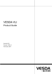
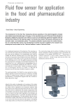
The standard sensor consists of a matched pair of elements, typically referred to as a
detector and compensator (reference element). The detector comprises a platinum
wire coil embedded within a bead of catalytic material. The compensator is similar
except that the bead does not contain catalytic material and as a consequence is inert.
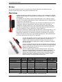
Figure 1 – Catalytic beads / Pellistors
Both elements are normally operated in a Wheatstone bridge circuit, that will produce an output only if
the resistance of the detector differs from that of the compensator.
The bridge is supplied with a constant dc voltage or current that heats the elements to 500-550°C.
Combustible gases are oxidised only on the detector element, where the heat generated increases its
resistance, producing a signal proportional to the concentration of combustible gas. The compensator
helps to compensate for changes in ambient temperature, pressure, and humidity, which affect both
elements equally.
Most catalytic based detectors have their pair of elements housed in separate metal cans. In a
complete gas detector the cans will normally be mounted inside an enclosure consisting of a metal
sinter and housing. This enclosure allows gas to reach the sensor whilst ensuring that the hot sensor
elements cannot ignite an explosive gas mixture.
Detection and alarm of flammable gases relies on the accurate measurement of flammable gases
below the LFL concentration. Safety applications, therefore, are not generally concerned with
measuring the volume concentration of gas. Measurements are more usually expressed as a
percentage of the LFL concentration of the gas (%LFL).
Most combustible gas detection techniques are designed to detect a wide range of gases. Ideally the
output of a sensor will be independent of the gas being measured. In reality, however, the variation in
physical properties affects the output. Catalytic oxidation sensors are no exception, so the response a
catalytic bead gives to the same volume concentration of different gases will vary. However when
exposed to the same %LFL concentration of different gases, the variation in output is fairly small
compared to other detection techniques. As safety applications are interested only in %LFL
measurements this is a major advantage.
The variation in output for the same %LFL concentration of different gases is termed 'relative
sensitivity'. Tests have been carried out to determine the experimental values of relative sensitivity for
the catalytic beads used within the VEDSA ECO to a range of combustible gases.
Catalytic Poisons
Certain substances are known to have a detrimental effect on catalytic sensors. There are two
mechanisms by which this can occur:
2
Doc. 18890_01
How VESDA ECO Works
Poisoning
Some compounds will decompose on the catalyst and form a solid barrier over the catalyst surface.
This action is cumulative and prolonged exposure will result in an irreversible decrease in sensitivity.
Typical poisons are organic lead and silicon compounds.
Inhibition
Certain other compounds, especially H2S and halogenated hydrocarbons, are absorbed or form
compounds that are absorbed by the catalyst. This absorption is so strong that reaction sites in the
catalyst can become blocked and normal reactions are inhibited. The resultant loss of sensitivity is
temporary and in most cases a sensor will recover after a period of operation in clean air.
In applications where either poisons or inhibitors are likely to be present, the VEDSA ECO should be
tested on a more frequent basis to ensure its’ ability to respond to gas.
Limitations of Use
Catalytic beads are designed to detect flammable gases within a background of ambient air and
require the presence of Oxygen to operate. Catalytic beads will not detect flammable gases in a
background of inert gas e.g. Nitrogen or Helium.
Cautionary Note Regarding ASD Pipework Installations
To ensure ease of maintenance, VESDA ECO must not be glued into ASD sampling pipework. It
should be noted that some glues used to permanently join ASD sample pipework and fittings contain
solvents which may result in a positive response on catalytic bead based detectors. Gas
commissioning procedures should only be carried out after these glues have fully cured.
*LFL Note: The LFL of a gas is the minimum concentration of that gas in air at which an ignition source
will cause an explosion.
How Electrochemical Cells Work
Electrochemical toxic gas sensors are micro fuel cells, designed to be maintenance-free
and stable for long periods. They have a direct response to volume concentration of gas
rather than partial pressure.
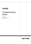
The simplest form of electro-chemical toxic sensor comprises two electrodes: sensing
and counter, separated by a thin layer of electrolyte. This is enclosed in a plastic
housing that has a small capillary to allow gas entry to the sensing electrode and
includes pins which are electrically attached to both electrodes and allow easy external interface.
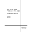
These pins may be connected to a simple resistor circuit that allows the voltage drop resulting from
any current flow to be measured (figure 2). Gas diffusing into the sensor is either oxidised or reduced
at the sensing electrode and, coupled with a corresponding (but converse) counter reaction at the
other electrode, a current is generated through the external circuit. Since the rate of gas entry into the
sensor is controlled by the capillary diffusion barrier, the current generated is proportional to the
concentration of gas present outside the sensor and gives a direct measure of the toxic gas present.
Doc. 18890_01
3
How VESDA ECO Works
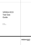
Figure 2 - Toxic Gas Sensor
The central feature of the design is the gaseous diffusion barrier, which limits the flow of gas to the
Sensing electrode. The electrode is therefore able to react all target gas as it reaches its surface, and
still has electrochemical activity in reserve. This high activity reserve ensures each cell has a long life
and excellent temperature stability.
2-Electrode sensors are the simplest form of toxic gas sensors. However they have limited measuring
range due to polarisation of the counter electrode. This polarisation effect can be eliminated by using a
third, reference, electrode with a stable potential in the sensor design. In these sensors the sensing
electrode is held at a fixed potential relative to the reference electrode (from which no current is
drawn) so both maintain a constant potential. The counter electrode is still free to polarise, but has no
effect on the sensing electrode and does not limit the sensor in any way. 3-Electrode sensors are the
most widely used design of electrochemical sensors for detecting toxic gases.
VESDA ECO uses 3 electrode electrochemical cells.
How Oxygen Sensors Work
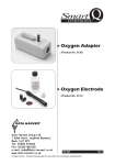
All electrochemical oxygen sensors are of the self-powered, diffusion limited, metal-air
battery type comprising an anode, electrolyte and an air cathode as shown.
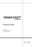
An oxygen cell can simply be considered as an enclosure (either a metal can or a
plastic moulding) which holds two electrodes: a flat PTFE tape coated with an active
catalyst, the cathode and a block of lead metal, the anode. This enclosure is airtight
apart from a small capillary at the top of the cell which allows oxygen access to the
working electrode. The two electrodes are connected, via current collectors, to the pins which protrude
externally and allow the sensor to be electronically connected to an instrument. The entire cell is filled
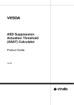
with conductive electrolyte which allows transfer of ionic species between the electrodes (figure 3).
Figure 3 – Schematic of oxygen sensor.
4
Doc. 18890_01
How VESDA ECO Works
The rate at which oxygen can enter the cell is controlled by the size of the capillary hole at the top of
the sensor. When oxygen reaches the working electrode, it is immediately reduced to hydroxyl ions:
These hydroxyl ions migrate through the electrolyte to the lead anode where they are involved in the
oxidation of the metal to its corresponding oxide.
As the two processes above take place, a current is generated which can be measured externally by
passing it through a known resistance and measuring the potential drop across it. Since the current
produced is proportional to the rate at which these reactions occur, its measurement allows accurate
determination of the oxygen concentration.
As the electrochemical reaction results in the oxidation of the lead anode these sensors have a limited
life. Once all the available lead has been oxidised they no longer work. Typically oxygen sensors have
1 – 2 year life times.
www.xtralis.com
The Americas +1 781 740 2223 Asia +852 2916 8894 Australia and New Zealand +61 3 9936 7000
Continental Europe +32 56 24 19 51 UK and the Middle East +44 1442 242 330
The contents of this document are provided on an “as is” basis. No representation or warranty (either express or implied) is made as to
the completeness, accuracy or reliability of the contents of this document. The manufacturer reserves the right to change designs or
specifications without obligation and without further notice. Except as otherwise provided, all warranties, express or implied, including
without limitation any implied warranties of merchantability and fitness for a particular purpose are expressly excluded.
This document includes registered and unregistered trademarks. All trademarks displayed are the trademarks of their respective owners.
Your use of this document does not constitute or create a licence or any other right to use the name and/or trademark and/or label.
This document is subject to copyright owned by Xtralis AG (“Xtralis”). You agree not to copy, communicate to the public, adapt, distribute,
transfer, sell, modify or publish any contents of this document without the express prior written consent of Xtralis.
Doc. 18890_01