1
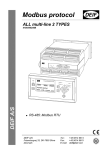
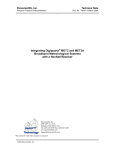
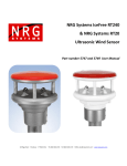
USER’s MANUAL/INSTALLATION NOTE
Wind Sensor type WSS REC
•
•
•
•
Mounting
Connection
Technical specifications
References
Document no.: 4189350037B
WSS REC
User’s Manual/Installation Note
Table of contents
1.
INTRODUCTION ......................................................................... 3
UNPACKING.................................................................................... 4
LEGAL INFORMATION AND RESPONSIBILITY ...................................... 4
2.
MOUNTING THE WIND SENSOR ............................................. 5
PLACING OF THE WIND SENSOR ...................................................... 5
BIRD AVOIDANCE KIT (OPTIONAL) .................................................... 7
3.
CABLE CONNECTIONS ............................................................. 9
THE WSS REC WIND SENSOR CABLE CONNECTIONS...................... 9
CONNECTOR KIT ASSEMBLY (OPTIONAL) ....................................... 10
4.
DIMENSIONS ............................................................................ 11
5.
TECHNICAL SPECIFICATION ................................................. 12
6.
REFERENCES........................................................................... 15
DEIF A/S
Page 2 of 15
WSS REC
User’s Manual/Installation Note
1. Introduction
This document provides guidelines for mounting and connecting the
WSS REC static wind sensor.
The ultrasonic wind measuring system used in the WSS REC is a fast
responding and accurate system designed for measurement of wind
speed and wind direction.
The sensor is based on three ultrasonic transducers arranged in a
triangle for measuring of wind speed and wind direction. By measuring
the time it takes for a set of ultrasound bursts to travel from each
transducer to the other two, the wind speed and direction can be
calculated.
The WSS REC has a built-in heater, which will automatically engage
when risk of icing occurs during low temperatures.
DEIF A/S
Page 3 of 15
WSS REC
User’s Manual/Installation Note
Unpacking
The WSS REC sensor is delivered in a cardboard box.
Inside this box, the sensor is packed in a white foam box (called a
protection cap), which is supposed to stay on, until the sensor is
mounted in the mast.
This will effectively protect the delicate sensor heads.
Do not remove the white protection cap or the tape
keeping it in place, before the sensor is mounted in the
mast!
The sensor is protected against ESD (static electricity), but it is
recommended to avoid static discharge trough the connection wires
during installation.
Legal information and responsibility
DEIF takes no responsibility for installation or operation of the wind
measuring system. If there is any doubt about how to install or operate
the WSS REC, the company responsible for the installation or the
operation of the product must be contacted.
The units are not to be opened by unauthorised personnel.
If opened anyway, the warranty will be lost.
DEIF A/S
Page 4 of 15
WSS REC
User’s Manual/Installation Note
2. Mounting the wind sensor
Placing of the wind sensor
Ideally, the wind sensor should be placed far from large objects that
might influence the measuring results; however, in practice this is
normally not possible on a wind turbine. The best result is achieved by
placing the wind sensor at the top of a mast in the opposite end of the
rotor.
Placing the sensor just above the nacelle and just behind the rotor is
disadvantageous. This may result in turbulence, velocities and wind
directions that are out of proportion to the actual, undisturbed wind
speed and wind direction.
The wind sensor is intended for installation on a vertical socket or a
tube using the stainless steel tap mounting base. See the drawing on
the next page for dimensions of the tap. The tap must not be
removed from the wind sensor, as this will damage the
waterproof sealing and the warranty will become void.
Do not expose the plastic part of the wind sensor to
any torque when mounting the sensor. The tools
used for fastening are only to be applied on the
actual tap.
DEIF A/S
Page 5 of 15
WSS REC
User’s Manual/Installation Note
Mount the WSS REC
Remove the protective cap
To
ensure
that
the
measurement represents the
precise wind direction relative
to the turbine, the wind sensor
must be aligned correctly. I.e.
when mounting the wind
sensor, the arrow on top (and
bottom) of the white protection
cap must be parallel with the
centre axis of the nacelle from
Protective cap
rotor to the back.
Note: An arrow pointing ahead
is also found on the bottom part of the sensor itself.
On land-based, non-rotating installations, the arrow must point towards
North.
Do not hit, squeeze or try to
remove the three black
rubber hoods!
Do not expose the plastic part of the wind sensor to any
torque when mounting the sensor; the tools used for
fastening are only to be applied on the actual tap.
DEIF A/S
Page 6 of 15
WSS REC
User’s Manual/Installation Note
Bird avoidance kit (optional)
The bird avoidance kit is designed to reduce the risk of birds landing on
the WSS REC and thereby interfering with measurements or even
damaging the sensitive ultrasonic transducer heads. The black rubber
heads are known to attract some birds’ attention, due to the click-sound
they produce. The bird avoidance kit is mounted as standard.
Please note that the kit does not provide complete protection against
birds, but especially large birds will not be able to land, whereas small
birds may still be able to squeeze in. Small birds may interrupt the wind
measurement, but will not be able to damage the sensor. The shape
and location of the spikes is designed so the interference with wind
measurements is negligible.
When the kit is mounted on the WSS REC sensor, more
snow may be able to accumulate on top of the sensor,
and it may melt slower.
Installation of the kit (retrofit only)
1. Position the metal ring with spikes
around the stainless steel top plate
of the WSS REC sensor. Position it
so the spikes do not block the direct
paths between the three black
rubber heads, see picture.
2. Secure the metal ring using the
M3x6 screw provided. It is
recommended to secure the screw
from loosening due to vibrations with
a drop of Loctite® super glue or
equivalent (not included in the kit)
and tighten the screw all the way in.
3. Check that the kit is fitted tightly on
the WSS REC.
DEIF A/S
Page 7 of 15
User’s Manual/Installation Note
49.5
82.4
149.8
25.0
198.0
WSS REC
114.0
127.0
¾” pipe thread:
Outer diameter: 1.04 inch
(26.4 mm), 14 threads per inch.
IMPORTANT!
The stainless steel mounting base on the WSS REC
sensor must be connected to earth (e.g. the steel hull).
DEIF A/S
Page 8 of 15
WSS REC
User’s Manual/Installation Note
3. Cable connections
The wind sensor is supplied with 10 metres fixed cable. From factory,
the cable is connected to the sensor via a waterproof gland, and this
must not be replaced by another cable. The cable can be extended by
using the connection box kit or the IP67 connector kit (both optional).
In order to protect the wind sensor and the personnel in the best
possible way from lightning strokes, use a lightning rod installed with
the tip at least one metre above the wind sensor. The lightning rod
must be properly grounded in compliance with all applicable safety
regulations. The wind sensor cable screen and the extension cable
screen must be connected.
For further protection of the cable from the wind sensor, it is
recommended to use a metal conduit pipe cable.
Suitable extension cable is available from DEIF at any length between
one and 300 metres. Alternatively, an installation cable, e.g. UL2464
2
18AWG4C + AE, 4 x 0.75 mm screened, can be used. The max.
length is 300 m, and maximum 70 nF capacity between the signal
conductors.
The WSS REC wind sensor cable connections
Cable
colour
Black
Red
Orange
Brown
Shield
Function
Supply
voltage
RS485
comm.
Cable shield
Note
+
A
B
9-31V DC supply for the WSS
REC wind sensor
Wind speed and direction data
output
Is connected to the stainless
steel tap inside the WSS REC
No supply voltage must be present during installation
of the wind sensor, as this will damage the wind
sensor.
DEIF A/S
Page 9 of 15
WSS REC
User’s Manual/Installation Note
Connector kit assembly (optional)
The connectors must be soldered onto the cable according to the
following instructions:
WSS fixed
cable
Connector
pin no.
WSS extension
cable
Male
connector
Female
connector
Plug male 7 pin.
10 22 00 00 52
Plug female 7 pin.
10 22 00 00 53
Screw cap male,
10 29 92 00 02
Screw cap female,
10 29 92 00 03
Black (-)
Red (+)
Orange
Brown
Screen
●
●
●
●
●
1
2
3
4
5
Black (-)
Red (+)
Orange
Brown
Screen
Signal
comments
●
●
●
●
●
30V DC supply
for WSS REC
RS485 comm.
from WSS REC
Cable screen
Measures are in mm
DEIF A/S
Page 10 of 15
WSS REC
User’s Manual/Installation Note
DEIF A/S
¾” pipe thread:
Outer diameter:
1.04inch (26.4 mm),
14 threads per inch
114.0
127.0
49.5
82.4
149.8
198.0
4. Dimensions
Page 11 of 15
WSS REC
User’s Manual/Installation Note
5. Technical specification
Sensors are designed according to the standards
Standards
below
Power supply 12/24 V (9.0…31.2V DC)
Power
WSS REC with inactive heating element:
consumption
<0.1 W
WSS REC with maximum heating:
<15 W
Interface
RS485 bus:
The bus should be terminated with 120 to
200 ohm for pure RS485 operation
RS422 bus:
For single listener connection on RS422,
the data line must be terminated with a
200 to 250 ohm resistor to obtain the
necessary output
Data sentence $WIMWV – Wind speed and direction data NMEA 0183
$WIXDR – Transducer measurement
ver. 3.0
response
$WITXT – Error messaging
For details, see doc. no. 4189350038,
Appendix to User's Manual, WSS REC
Wind speed
Range:
0….60 m/s
Resolution: 0.1 m/s
Accuracy: 0…35 m/s: ±0.3 m/s or ±3%,
whichever is
greater
>36 m/s: ±5%
o
Wind direction Range:
0…. 360 continuously
o
Resolution: 1
Accuracy: ±3% in relation to wind
direction
Update interval 1 sec.
Start-up time
<5 sec. from power on to valid data output
DEIF A/S
Page 12 of 15
WSS REC
User’s Manual/Installation Note
Sensors are designed according to the standards
below
2
Connection
10 metres 4 x 0.75 mm screened cable
type UL2464
18AWG/4C+DW+AL/MY+Jacket
The 10 m cable is fixed on the sensor and
is open-ended
Mounting
¾” pipe thread: Outer diameter:
1.04 inch (26.4 mm), 14 threads per inch
Protection
IP66
Relative
humidity
Pressure
Temperature
Vibration test
Safety
EMC
Housing
Weight
Dimensions,
cardboard box
DEIF A/S
0…100%
600…1100 hPa
WSS REC operating range:
-52…+60°C (class approved for:
-25…+60°C)
Storage (both):
-60…+70°C
3…13.2 Hz: 2 mm (peak-peak)
13.2…100 Hz: 0.7 g
3…15 Hz:
+ 2.5 mm (peak)
15…50 Hz: 2.3 g
Cat. III, poll. dg. 2, 550V AC rms, 50 Hz,
1 minute
CE-marked for industrial environment
Wind sensor housing:
Polycarbonate +10% glass fibre
Mounting tap:
Corrosion-resistant stainless steel
0.8 kg
450 x 315 x 230 mm
Standards
IEC 529 and
EN 60529
EN/IEC
60068-1/2
EN 60051
EN 60945,
EN/IEC600
68-2-6 and
DNV Class
A
GL curve 4
for masts
EN 61010-1
EN 610001-1/2/3/4
UL94 V0
Page 13 of 15
WSS REC
User’s Manual/Installation Note
Sensors are designed according to the standards
Standards
below
Accessories
IP66 connection box kit: IP66 connection
box with cable glands and screw terminals
to extend the sensor cable with an
extension cable
IP67 connector kit: Watertight male and
female connector for soldering to the
sensor cable and the extension cable
respectively
Extension cable: 1 to 300m shielded cable,
DEIF ID no.1020230016
Bird avoidance kit (standard, retrofit only):
Spike kit to prevent birds from interrupting
the wind measurements or, in worst case,
from damaging the sensor
DEIF A/S
Page 14 of 15
WSS REC
User’s Manual/Installation Note
6. References
For more details, please refer to the following documentation:
Appendix to User’s Manual, WSS REC, document no. 4189350038.
Documentation is available at www.deifwindpower.com – Download
centre.
DEIF A/S reserves the right to change any of the above.
DEIF A/S
Page 15 of 15