1
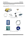
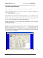
Paroscientific, Inc. Technical Note Precision Pressure Instrumentation Doc. No. G8036 Rev. NC 25 November 2003 Integrating Digiquartz® MET3 and MET3A Broadband Meteorological Systems with a Trimble NetRS GPS Receiver Paroscientific, Inc. 4500 148th Ave. N.E. Redmond, WA 98052, USA Tel: (425) 883-8700 Fax: (425) 867-5407 www.paroscientific.com [email protected] “The standard by which other standards are measured” 2003 Paroscientific, Inc. Paroscientific, Inc. Technical Note Precision Pressure Instrumentation Doc. No. G8036 Rev NC 25 November 2003 Integrating Digiquartz® MET3 and MET3A Broadband Meteorological Systems with a Trimble NetRS GPS Receiver By Mustafa Yilmaz [email protected] 1. Introduction Paroscientific’s MET3 and MET3A Broadband Meteorological Measurement Systems were specifically designed for GPS-Meteorology and geophysical applications. For both of these applications, it is necessary to calculate the amount of precipitable water vapor (PWV) in the atmosphere for very accurate position measurements or short-term weather forecasts (nowcasting). For these applications, precision, accuracy, reliability, and long-term stability of the MET stations correspond to low total cost-of-ownership in the long run. The broadband feature of these instruments also enables scientists to measure other atmospheric and geophysical signals with a network of GPS receivers colocated with Digiquartz® MET3 and MET3A Meteorological Measurement Systems. The purpose of this document is to provide specific integration and diagnostics information, additional to the MET3 and MET3A User’s Manual, to facilitate the integration of a MET station with a Trimble NetRS GPS receiver. Once the MET stations are set up properly in the field, these instruments are designed to work under rugged environmental conditions for years without problems. The operating principle of a MET station with a GPS receiver is simple and relies on a few critical parameters. This technical paper elaborates on these critical parameters and provides a technical recipe to integrate a Trimble NetRS GPS receiver with a MET station. Since surface pressure and temperature measurements are vital parameters for PWV calculations, the data reliability and integrity from the MET stations are of paramount importance. 2. MET3 & MET3A Broadband Meteorological Systems Performance Summary The MET3 and MET3A precision measurement instruments provide high accuracy data from barometric pressure, temperature, and relative humidity sensors. Pressure resolution is better than 1 microbar with a total accuracy of ±0.08 hPa over the extended barometric range of 620 to 1100 hPa. Temperature resolution is 0.01 degree C. The fan-aspirated MET3A has a total temperature accuracy of 0.1 degree C over the operating temperature range of –50 to +60 degrees C. Relative humidity performance is better than 2% at 25 degrees C, and humidity recovery time for the MET3A after 100% water saturation is less than 2 minutes. These fully integrated systems are housed in environmental enclosures allowing stand-alone, indoor or outdoor mounting. Installation hardware and software are included, and optional interface cabling is available for easy system integration. The MET3 radiation shield protects the temperature and humidity sensors from precipitation and solar radiation. The MET3A utilizes a high performance, tuned barometric pressure port to reduce dynamic pressure errors caused by wind. Microprocessor-based electronics provide fully temperature compensated and linearized outputs via a two-way RS232 interface. The serial interface allows complete remote configuration and control of all operating parameters including resolution, sample rates, choice of engineering units, integration time, and sampling commands. Individual measurement parameters or a “unified” data word with all sensor outputs are easily interfaced with computer systems, GPS receivers, and data loggers. 2003 Paroscientific, Inc. 2 Paroscientific, Inc. Technical Note Precision Pressure Instrumentation Doc. No. G8036 Rev NC 25 November 2003 3. What do you need for GPS-MET Integration? Purchase of Trimble NetRS and a Broadband Digiquartz® MET3 or MET3A Meteorological package should include the following items from each vendor. If any of these items are missing from your package, please contact Trimble or Paroscientific, Inc. GPS Receiver Ethernet Cable GPS Antenna (comes with cable) RS-232 Service Cable Power & Ethernet Port Power Adapter Table 1. Items provided by Trimble MET Station MET Cable (optional) Power breakout/supply kit (optional) Digiquartz® Software CD Table 2. Items provided by Paroscientific 2003 Paroscientific, Inc. 3 Paroscientific, Inc. Technical Note Precision Pressure Instrumentation Doc. No. G8036 Rev NC 25 November 2003 4. Operating Principle of MET Stations MET stations include the world’s most accurate, stable, and reliable Broadband Digiquartz® Barometers, environmentally packaged with a precision temperature and humidity probe. Integral electronics and integrated, compact packaging make installation and communication with these instruments an easy task. In order for a MET station to work wit h any GPS receiver, regardless of the GPS receiver manufacturer, the following conditions must be met. a. The MET instrument must be powered up. Paroscientific MET stations require a power source providing a voltage output of +7 to +16 VDC through pin 9 of its RS-232 connector. Some GPS receivers (e.g. Thales) provide power on pin 9 of the RS-232 cable. Trimble NetRS does not provide power through its communication ports. So, you have to use the power adapter kit optionally supplied by Paroscientific, Inc. If you don’t have this kit, please contact Paroscientific Sales and Application engineers to get the power breakout/ supply kit (Part Number 1727-00X: X=1 for 110 VAC, for 220 VAC X=2). You may order this kit during your purchase of the MET station as well. Note: MET stations shipped after 8/02 have Power & Status LEDs, which indicate the instrument is powered up and/or transmitting/receiving data. b. The MET station must be set to transmit pressure data in units of “bar” (UN=3). MET stations have 8 user-selectable pressure units available. However, MET stations will only respond to commands sent from a GPS receiver when the pressure unit is set to “bar”. Broadband MET3 and MET3A Meteorological Measurement Systems’ pressure units are preset to “bar” by the factory before shipment. This corresponds to UN parameter (set to) “3” in the configuration. If your instrument is set to a different pressure unit, you can use the Digiquartz® Interactive (DQI) software (provided with the MET station) to change the pressure unit as illustrated in Figure 1. To download the most recent version of the DQI software, please visit our web site at http://www.parosceintific.com/software.htm. Figure 1. MET Station pressure unit must be set to UN=3 (bar) 2003 Paroscientific, Inc. 4 Paroscientific, Inc. Technical Note Precision Pressure Instrumentation c. Doc. No. G8036 Rev NC 25 November 2003 Correct cable type between the GPS receiver and MET station must be used. Paroscientific provides (optionally available) GPS-to-MET interface cables. This cable connects the MET station directly to the GPS, or to another GPS interface cable provided by the GPS receiver manufacturer. If you are using a custom-made cable or don’t have the right GPS cable to interface with the MET cable, you may experience communication problems. If you are using a custom-made MET cable, please check the MET3 and MET3A User’s Manual to see the pin connections. d. The GPS receiver must be configured to send a P9 command to the MET station. Once the GPS receiver and MET station are connected and powered up, the MET station is ready to respond to a P9 command issued from the GPS receiver. The GPS receiver must be configured to send a P9 command to the MET station. The MET station returns the pressure, temperature and humidity in standard NMEA 1 format. *(Two-digit address of the MET Station)00P9 <cr><lf> In this format, (Two-digit address of the MET Station) corresponds to the address of your MET station. By default, it is “01”. If you changed this address, please use the correct address in the format above. If you did not change the address of the MET station, *0100P9<cr><lf> command should be issued by the GPS receiver to get a response from the MET station. The <cr> and <lf> correspond to carriage return (Character 13) and line feed (Character 11). The MET station P9 command only works with a single device. It will not work in an RS-232 loop. A typical response to a P9 command is as below. $WIXDR,P,<Pres Value>,B,<SN>,C,<Temp value>,C,<SN>,H,<Hum value>,P,<SN><CR><LF> +-- Pressure --+ +- Temperature - + + - - Humidity - - + Transducer Field Units Pressure P B=Bar Temperature C C=Celsius Humidity H P=Percent <SN> = Transducer Serial Number (Typically - DQ#####) This response will be parsed out and stored in your GPS receiver. 1 The NMEA 0183 (National Marine Electronics Association) Standard for Interfacing Marine Electronics Devices is a voluntary industry standard, first released in March of 1983. The NMEA has become a standard protocol for interfacing navigational devices such as GPS and DGPS receivers. It defines electrical signal requirements, data transmission protocol, timing and specific sentence formats. 2003 Paroscientific, Inc. 5 Paroscientific, Inc. Technical Note Precision Pressure Instrumentation Doc. No. G8036 Rev NC 25 November 2003 5. Getting Acquainted with the Trimble NetRS GPS Receiver The Trimble NetRS receiver is a dual-frequency GPS receiver, which runs on a Linux operating system and communicates through local and wide area networks. All operating controls, ports and connectors on the NetRS are either on the front or back panel. Figure 2 shows the front panel LEDs, service port (Port 1) and the power button. Service Port Ethernet Data Logging Satellite Tracking Secondary Power Primary Power Power Button Figure 2. Trimble NetRS GPS Receiver Front Panel Service Port (Port 1) is used for initial configuration, IP address assignment and servicing the unit. The default parameters for the RS-232 communication are 115,200 baud rate, 8 data bits, No parity and 1 stop bit. Linux diagnostics messages are also available through this port during boot and shutdown processes. Power button is used to control the GPS receiver’s power states. LED status is summarized in the table below. LED External Frequency Ethernet Satellites Logging Amber Power Green Power Status Shows if there is an external frequency source. On when Ethernet cable is connected. Flashing when there is network traffic. Off when there are no satellites to track. Flashes slowly when tracking fewer than four satellites. If more, flashes faster. Flashes slowly when logging data. On when power source is healthy but not in use. Flashing quickly when power source is low but in use. On when power source is healthy (12 V or more). Flashing when power source is low. Table 3. Trimble NetRS LED Functions To review the details of the LED status codes, please review the NetRS GPS Receiver User Guide from Trimble. Figure 3 shows the Trimble NetRS back panel and connectors. A brief description of each back panel item is as below. Antenna port connects to the GPS antenna. Multi-port adapter port is used to provide power and Ethernet connectivity (10BaseT) to the instrument. Side A of this cable is connected to the port labeled “Primary Power”, Side B of the cable is connected to an Ethernet cable and power adapter. Please pay special attention to the type of cable used to connect the GPS receiver to different Ethernet devices (straight through vs. crossover cables). Use a straight through cable when connecting to a hub or a 2003 Paroscientific, Inc. 6 Paroscientific, Inc. Technical Note Precision Pressure Instrumentation Doc. No. G8036 Rev NC 25 November 2003 switch. Use a crossover cable when connecting directly to a computer Ethernet card. Multi-port adapter cable details are as illustrated in Figure 4. Figure 3. Trimble NetRS GPS Receiver Back Panel RS-232 Ports (Port 2, Port 3 and Port 4) are used to connect to a MET3/3A Broadband Meteorological Measurement System. Figure 4. Trimble Multiport Adapter Primary Power/Ethernet port is used to provide power and Ethernet access to GPS receiver. Connect the Side A of the Trimble Multi-port adapter seen in Figure 4 to this port. 2003 Paroscientific, Inc. 7 Paroscientific, Inc. Technical Note Precision Pressure Instrumentation Doc. No. G8036 Rev NC 25 November 2003 6. Trimble NetRS and MET Integration Procedure To integrate a Trimble NetRS GPS receiver with a Paroscientific MET station. You will need a notebook or desktop computer to configure the receiver and access data files. a. Connect the appropriate end of the RS-232 cable that came with your GPS receiver to the port1/service on the front panel of your GPS receiver and the other end to RS-232 port of your computer as in Figure 5. Figure 5. Front Panel Service Port RS-232 Connection b. c. Connect the Trimble Multiport adapter to the Primary Power port on the back of the NetRS receiver. At this time, do not connect the power adapter to the multi-port adapter. This will be done in step (e). Connect the GPS antenna cable to the GPS port on the back panel as in Figure 6. Figure 6. Back Panel Antenna and Power Connection d. In MS-Windows, use HyperTerminal to configure a session to access the Trimble GPS receiver via the RS232 port to which NetRS is connected. The HyperTerminal program is located in the Accessories and Communication menus. Configure the HyperTerminal session as shown in Figure 7. Select the COM Port to which the GPS receiver is connected. By default, GPS receiver has 115200 baud rate, 8 data bits, No parity and flow control OFF. Click on the OK button. 2003 Paroscientific, Inc. 8 Paroscientific, Inc. Technical Note Precision Pressure Instrumentation Doc. No. G8036 Rev NC 25 November 2003 Figure 7. MS -Windows HyperTerminal Configuration e. f. When the HyperTerminal status bar shows Connected, Connect the power adapter to the power connection port on side B of the multiport adapter as seen in Figure 6. The GPS receiver’s operating system will start booting and sending messages to the HyperTerminal window. Follow the messages on the screen. When the message from the GPS receiver asks, do you want to change Ethernet Configuration (Yes/No?), type Yes and press the enter key. This will give you an opportunity to enter the new network parameters. Please talk to your network administrator or Internet Service Provider to get an IP address, subnet mask and the gateway address. Once these parameters are entered, the receiver will ask you to confirm the parameters as in Figure 8. Figure 8. NetRS Ethernet Interface Configuration 2003 Paroscientific, Inc. 9 Paroscientific, Inc. Technical Note Precision Pressure Instrumentation g. h. i. Doc. No. G8036 Rev NC 25 November 2003 If your operating system is not MS-Windows, you can use any terminal program that can access your COM ports to configure the GPS receiver and the Ethernet interface. After the GPS receiver completes initialization, connect the Ethernet cable that came with your GPS receiver to the Ethernet Connection port on side B of the multiport connector (as seen in Figure 4 and Figure 6). Connect the other end of the Ethernet cable to a hub or switch in your network. At this point, you should be able to access the Trimble NetRS receiver over the Ethernet network via a web browser. Launch your web browser and in the address line type the IP address of your GPS receiver. For this technical note, we will use http://192.168.100.5. Once you launch your browser, you will see the GPS receiver home page in Figure 9. Figure 9. GPS Receiver Home Page j. k. l. You are now ready to connect the MET station to the GPS receiver and configure the GPS receiver to log data from the MET station. As mentioned before, as opposed to some other GPS receivers (e.g. Thales), Trimble NetRS does not provide power to the MET station. You need the power breakout/supply kit available from Paroscientific (See Table 2). Connect the MET cable to the power breakout adapter and connect and secure the adapter to Port 2 or Port 4 on the back panel of the GPS receiver as shown in Figure 10. When you connect the MET cable to the power adapter and supply power, the MET station power LED (red) should turn on as in Figure 11. The MET station connection to the power breakout adapter and the GPS receiver will be the same as the PC connection as in Figure 16 except the connection will be made to the NetRS instead of a PC. At this point the MET station is ready to respond. It is now time to configure the GPS receiver to interrogate the MET station periodically. 2003 Paroscientific, Inc. 10 Paroscientific, Inc. Technical Note Precision Pressure Instrumentation Doc. No. G8036 Rev NC 25 November 2003 Multiport Adapter GPS Antenna MET Station Connection Ethernet Cable Power Cable Figure 10. MET Connection to NetRS Figure 11. MET Station LEDs (Power –ON) m. In the GPS receiver home page, click on the I/O Configuration menu option to the left of the screen. You will be presented with different port options as in Figure 12. Select the COM port that the MET station is connected to. We will use Port 2 in this technical note. 2003 Paroscientific, Inc. 11 Paroscientific, Inc. Technical Note Precision Pressure Instrumentation Doc. No. G8036 Rev NC 25 November 2003 Figure 12. Trimble NetRS Serial Port Configuration n. o. In the I/O Configuration page, click on the Serial Port 2 link. This opens the Port Configuration window. In this window, click on the Met-Tilt option. This will bring up the window in Figure 13. Set Baud to 9600, Parity and Flow Control to None. At the bottom of the screen in the first Command box, enter “*0100P9\r\n”. If you set the ID of your MET station to a value other than “01”, make sure to change that in the command string as well. Figure 13. Trimble NetRS MET Port Configuration 2003 Paroscientific, Inc. 12 Paroscientific, Inc. Technical Note Precision Pressure Instrumentation p. Doc. No. G8036 Rev NC 25 November 2003 Click on the OK button. You will see the Port Configuration window in Figure 12 again. This time the port you just configured will show “Met-Tilt” across the port number. To start logging data in the GPS receiver, you must enable datalogging. Click on the Data Logging menu option. You will see a window similar to the one in Figure 14. Figure 14. Trimble NetRS Data Logging Configuration q. r. s. t. In data logging screen, create a new session by clicking on the “Create a New Session” link. Assign a name to the new session and click on the OK button. If you would like to start logging data immediately, select the Enable check box. You can also start or stop a datalogging session any time from the datalogging menu. Once datalogging is enabled, NetRS interrogates the MET station at the interval it was set to. After logging is enabled, observe the TX and RX lights to see if MET station receives and transmits data. If the MET station receives a command from NetRS, the RX LED will blink. TX LED will blink when it transmits data. Unless NetRS logging session is disabled, it continuously logs position and MET data. You can access these files, download them or delete them via your web browser from the Data Files submenu under the Data Logging menu. To access the active file, you must disable datalogging first. For FTP access to the NetRS unit and downloading and converting the data files to RINEX format, please see the instructions in NetRS User Manual. 2003 Paroscientific, Inc. 13 Paroscientific, Inc. Technical Note Precision Pressure Instrumentation Doc. No. G8036 Rev NC 25 November 2003 Figure 15. NetRS Data Flies Access 6. Troubleshooting The MET Station Before integrating your GPS and MET station, or in the event of communication loss between a GPS receiver and a MET station, the MET station should be tested separate from the GPS receiver. To perform this test, please follow these steps. a. b. Connect the MET station to a laptop computer via the MET station interface cable and the power breakout as in Figure 16. Since PC’s are not equipped to power up a MET station, a power breakout must be used. The power breakout must be connected to the PC’s serial port and plugged into the MET station RS-232 cable. If your MET station has LEDs, you should see the red power light ON. The power for the MET unit is +7 to 16 VDC. Download our setup and configuration software Digiquartz® Interactive (DQI) from www.paroscientific.com/software.htm or load it from the Digiquartz® CD Library that was shipped to you with the purchase of your MET station. Figure 16. MET to PC Connection 2003 Paroscientific, Inc. 14 Paroscientific, Inc. Technical Note Precision Pressure Instrumentation c. d. e. f. g. Doc. No. G8036 Rev NC 25 November 2003 Start the DQI program. Select the Communication Port to which the MET station is connected and press “Start”. The communication baud rate of the unit has been pre-set to 9600 baud, 8 data bits, and 1 stop bit. DQI will try to communicate with an Intelligent Instrument on the selected Communication Port by using a succession of baud rates. The screen will display a baud rate and instrument identification numbers upon successful communication. If your instrument is powered up (see the LED) and DQI cannot detect your MET station, there is either a problem with the interface cable or the MET station. Please make sure to use the original MET station cable and power breakout (Part Number 1727-00X, X=1 for 110 VAC, X=2 for 220VAC) supplied by Paroscientific. If the problem continues, and you are sure you are not having a cabling problem, please contact us at (425) 883-8700 or at [email protected]. If DQI detects your instrument, click on the “OK” button. You should now see the DQI “Configuration” screen. On this screen, click on the “Start” button to read the configuration parameters of your MET station. Check the “Pressure Unit (UN)” parameter. Make sure that it is set to bar (factory default). If it is not in bar, click on the pressure unit field and select “bar”, then click on the “OK” button. Make sure that the pressure unit field is changed to “bar” on the screen. On the top menu bar, click on “Measure” and select MET3 from the drop-down list. The MET measurement panel will appear on the screen. Each measurement parameter has its own window. Verify that the pressure, temperature, and humidity fields have a reasonable data value. If any field displays “-----” characters, there may an instrument problem. Try increasing the time-out value on this screen to see if it will solve the problem. If it does not, contact our support department. The DQI Help file also has troubleshooting suggestions. In early 2002, a status indicator panel (LEDs) was added to the MET stations. These status indicators allow you to determine whether input power is supplied to the unit and to monitor RS-232 serial activity. The status indicator panel is located on the bottom surface of the unit, adjacent to the electrical connector. The following table explains the function of the status indicators: Indicator color Red Function ON: Input power on OFF: Input power off Green FLICKERING: Activity on RS-232 receive line OFF: No activity on RS-232 receive line Yellow FLICKERING: Activity on RS-232 transmit line OFF: No activity on RS-232 transmit line Table 4. MET LED Status h. The RS-232 interface is capable of driving signals over distances of up to 30 meters with good quality shielded cable. It is recommended that you bench test your unit with the installation cable, especially if you are driving the signal a long distance. i. If your MET station seems to be operating properly and you can not make the GPS receiver communicate with the MET station, this means there is either a problem with the connection between the GPS receiver and MET station or a configuration problem with the GPS receiver. j. Please make sure that when the GPS receiver cable is connected to the RS-232 cable of the MET station, the Power LED on the MET station must be “ON”. k. If you still can’t log data, make sure that the logging feature is on and enabled. Review the steps in section 5 of this document. l. If you still cannot log data from the GPS receiver and your MET station has passed the stand-alone communication test explained in steps 1-6 of this section, please contact Trimble technical support. m. If you are still having problems with the MET station, please contact Paroscientific’s Application Support Engineers either at (425) 883-8700 or send a description of your problem including the serial number of your instrument via e-mail to [email protected]. 2003 Paroscientific, Inc. 15