1
User Guide
FS24X HART Module
Honeywell Analytics
6349-001
Fire Sentry Corporation
TABLE OF CONTENTS
1. Introduction ................................................................................................................................ 4
1.1 Scope .............................................................................................................................. 4
1.2 Purpose ........................................................................................................................... 4
1.3 Who should use this document? ...................................................................................... 4
1.4 Abbreviations and definitions ......................................................................................... 4
1.5 References ...................................................................................................................... 4
2. Device Identification .................................................................................................................. 5
3. Product Overview ....................................................................................................................... 5
4. Product Interfaces ....................................................................................................................... 5
4.1 Process Interface ............................................................................................................. 5
4.1.1
Sensor Input Channels ...................................................................................... 5
4.2 Host interface ................................................................................................................. 5
4.2.1
Analog Output 1: Loop Current ........................................................................ 5
4.3 Local Interfaces, Jumpers and Switches .......................................................................... 6
4.3.1
Local Controls and Displays ............................................................................. 6
4.3.2
Internal Jumpers And Switches......................................................................... 6
4.3.3
Connection Summary ....................................................................................... 7
5. Device Variables ........................................................................................................................ 8
6. Dynamic Variables ..................................................................................................................... 9
7. Status Information ...................................................................................................................... 9
7.1 Device Status .................................................................................................................. 9
7.2 Extended Device Status .................................................................................................. 9
7.3 Additional Device Status (Command #48) .....................................................................10
8. Universal Commands ................................................................................................................11
9. Common-Practice Commands ...................................................................................................11
9.1 Supported Commands ....................................................................................................11
9.2 Burst Mode ....................................................................................................................11
9.3 Catch Device Variable ...................................................................................................11
10. Device-Specific Commands ......................................................................................................11
11. Tables 12
11.1 Engineering Unit Type Codes ........................................................................................12
11.2 Loop Current Operating Modes......................................................................................12
Revision 1.2, Release Date: 15 February 2013
Page 2 of 16
Honeywell Analytics
6349-001
Fire Sentry Corporation
12. Performance ..............................................................................................................................12
12.1 Sampling Rates ..............................................................................................................12
12.2 Power-Up ......................................................................................................................12
12.3 Self-Test ........................................................................................................................13
12.4 Command Response Times ............................................................................................13
12.5 Busy and Delayed-Response ..........................................................................................14
12.6 Long Messages ..............................................................................................................14
12.7 Non-Volatile Memory....................................................................................................14
12.8 Modes ............................................................................................................................14
12.9 Write Protection.............................................................................................................14
12.10 Damping .....................................................................................................................14
Annex A. Capability Checklist .......................................................................................................15
Annex B. Default Configuration ....................................................................................................16
Revision 1.2, Release Date: 15 February 2013
Page 3 of 16
Honeywell Analytics
6349-001
Fire Sentry Corporation
1. INTRODUCTION
1.1 Scope
The Fire Sentry FS24X Flame Detector with HART® complies with HART® Protocol
Revision 7.0. This document specifies device features and HART® protocol implementation
details. The functionality of this Field Device is described sufficiently to allow its proper
application in a process and its complete support in HART-capable Host Applications.
1.2 Purpose
This specification is designed to complement other documentation (e.g., the FS24X
Installation Guide and Operating Manual) by providing a complete, unambiguous
description of this Field Device from a HART communication perspective.
1.3 Who should use this document?
The specification is designed to be a technical reference for HART®-capable host application
developers, system integrators and knowledgeable end-users. It also provides functional
specifications used during Field Device development, maintenance, and testing. This
document assumes the reader is familiar with HART® Protocol requirements and
terminology.
1.4 Abbreviations and definitions
IR
Infrared
PV
Primary Variable
EEPROM
Electrically-Erasable Read-Only Memory
ROM
Read-Only Memory
1.5 References
-
HART Smart Communications Protocol Specification. HCF_SPEC-12. Available
from the HCF.
-
FS24X Installation Guide and Operating Manual, Document 6178-001. Available
from Honeywell Analytics .
Revision 1.2, Release Date: 15 February 2013
Page 4 of 16
Honeywell Analytics
6349-001
Fire Sentry Corporation
2. DEVICE IDENTIFICATION
Manufacturer Name:
Honeywell
Analytics
Model Name(s):
FS24X
Manufacture ID Code:
210
Device Type Code:
130
HART Protocol Revision
7.0
Device Revision:
1
Number of Device Variables
None
Physical Layers Supported
FSK
Physical Device Category
Sensor and Transmitter
(D2 Hex)
(82 Hex)
The FS24X HART® module is identified by a serial number that begins with “24X-“. This
serial number will be visible on the module circuit card, along with a bar code containing the
same information.
The FS24X is designed to detect fire in a hazardous area. This device should be mounted so
as to avoid areas that contain non-fire radiant energy sources (such as radiant heaters, high
intensity lamps, etc.) in close proximity to the detector’s field of view. FS24X detectors
should be mounted so that they look downward with minimum twenty degree (20°) angle.
Avoid mounting the detectors in areas where temperatures are outside the specified operating
temperature range (-40°C to +85°C). Refer to the FS24X manual (SECTION 2:
INSTALLATION) for mounting instructions.
3. PRODUCT OVERVIEW
The FS24X is a Multi-Spectrum Flame Detector. A HART® communication module is
required for HART® communication.
4. PRODUCT INTERFACES
4.1 Process Interface
4.1.1 Sensor Input Channels
Fire Sentry multi-spectrum and multi-spectral infrared Flame Detectors are sophisticated,
state of the art, electro-optical digital radiant energy transducers that sense Wideband Infrared
radiant energy emitted by fire’s combustion processes that include molecular emissions and
hot particulate blackbody emissions. Additionally, the FS24X Detectors sense the specific
WideBand 4.3 IR “Triple IR” region from approximately 3 to 5 microns.
FS24X Detectors also utilize additional spectral regions, the Visible Band and Near Band
Infrared wavelengths, to aid in discrimination against non-fire false alarm sources.
4.2 Host interface
4.2.1 Analog Output 1: Loop Current
Loop current is the only output from this transmitter, representing the presence of flame in
the range of the instrument, as well as fault status. This output corresponds to the Primary
Variable. Refer to the section 4.3.3 for connection details.
Revision 1.2, Release Date: 15 February 2013
Page 5 of 16
Honeywell Analytics
6349-001
Fire Sentry Corporation
4.3 Local Interfaces, Jumpers and Switches
4.3.1 Local Controls and Displays
This device has no external local controls.
The indication of a detected malfunction is shown by reducing the loop current output to 1
mA. The FS24X Flame Detector uses three (3) separate, bright LED’s to indicate the
Detector’s status. The Blue or Green LED blinks (flashes) once every ten (10) seconds to
indicate a Normal, safe operational condition (i.e. no Faults and no Alarms). The Blue or
Green LED is OFF when no external 24 VDC input power is applied to the Detector. The
Red LED turns ON when a fire is detected. The Yellow LED blinks (flashes) when the
window lens is dirty. The dirty-lens condition also results in a loop current of 2 ma. For all
other Fault conditions, the Yellow LED will turn ON.
4.3.2 Internal Jumpers And Switches
Revision 1.2, Release Date: 15 February 2013
Page 6 of 16
Honeywell Analytics
6349-001
Fire Sentry Corporation
There are no jumpers or switches on the HART® module. Refer to the FS24X Installation
Manual for information relating to switch selections on the detector.Write Protection
Not Supported.
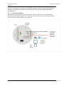
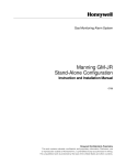
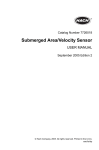
4.3.3 Connection Summary
The diagrams below provide connection detail. The first shows how the FS24X Flame
Detector plus the HART module connect to the outside world. The second diagram shows
how the detector and the module mate together.
Revision 1.2, Release Date: 15 February 2013
Page 7 of 16
Honeywell Analytics
6349-001
Fire Sentry Corporation
5. DEVICE VARIABLES
This Field Device does not expose any Device Variables.
Revision 1.2, Release Date: 15 February 2013
Page 8 of 16
Honeywell Analytics
6349-001
Fire Sentry Corporation
6. DYNAMIC VARIABLES
Only one Dynamic Variable is implemented.
Meaning
PV
Loop Current
Units
mA
7. STATUS INFORMATION
7.1 Device Status
Bit 7 ("Device Malfunction") is set when ever device reports any fault. Refer user manual for
description of fault conditions.
Bit 5 ("Cold start") is set whenever device resets or first powers up.
Bit 4 ("More Status Available") is set whenever any failure is detected or change in operating
mode. Command #48 gives further detail. (See section 7.3.)
Bit 3 ("Analog channel fixed") is set whenever the device into forced current or inhibit or
multi-drop.
7.2 Extended Device Status
The Field Device cannot predict, in advance, when the maintenance will be required. "Device
Variable Alert" is set when the PV is not indicating normal conditions, i.e. when an
instrument detects the presence of a flame.
Revision 1.2, Release Date: 15 February 2013
Page 9 of 16
Honeywell Analytics
6349-001
Fire Sentry Corporation
7.3 Additional Device Status (Command #48)
Command #48 returns nine bytes of data, with status information available in bytes #6 and
#8, as indicated in the following table:
Byte
Bit
Meaning
Condition
0
0 to 7
Not used
1
0 to 7
Not used
2
0 to 7
Not used
3
0 to 7
Not used
4
0 to 7
Not used
5
0 to 7
Not used
6
0
Detector Fault
Lid off or dirty, temperature or
voltage out of range, or internal
failure
1
Detector Alarm
Flame detected
2
Not used
3
Not used
4
Not used
5
Not used
6
Not used
7
Not used
7
0 to 7
Not used
8
0
Not used
1
Not used
2
Not used
3
Not used
4
Power Supply Conditions Out Of
Range
5
Not used
6
Not used
7
Not used
Voltage fault
"Not used" bits are always set to 0. In each case, bit #0 is the low-order bit.
Revision 1.2, Release Date: 15 February 2013
Page 10 of 16
Honeywell Analytics
6349-001
Fire Sentry Corporation
8. UNIVERSAL COMMANDS
Command #3 returns PV, units, and Loop Current. The first (PV) and the last (Loop Current)
variables are same.
Command #14 contains serial number of the device (3 bytes), followed by measurement units
(1 byte) and 3 floating point variables for max, min, and span loop current in mA.
9. COMMON-PRACTICE COMMANDS
9.1 Supported Commands
The following common-practice commands are implemented:
38
Reset "Configuration Changed" Flag
48
Read Additional Device Status
Command #48 returns 2 bytes of data.
9.2 Burst Mode
This Field Device does not support Burst Mode.
9.3 Catch Device Variable
This Field Device does not support Catch Device Variable.
10. DEVICE-SPECIFIC COMMANDS
The Field Device does not support any device-specific commands.
Revision 1.2, Release Date: 15 February 2013
Page 11 of 16
Honeywell Analytics
6349-001
Fire Sentry Corporation
11. TABLES
11.1 Engineering Unit Type Codes
Code
Description
Note
39
milliamperes
Electrostatic Unit of Current
11.2 Loop Current Operating Modes
Mode
Description
Loop Current in mA
(Point to Point )
Loop Current in mA
(Multi-drop)
0
Healthy
4mA
4mA
1
Optical
Fault
2mA
4mA
2
Non-Optical
Fault
1mA
4mA
3
Alarm
20mA
4mA
12. PERFORMANCE
12.1 Sampling Rates
Typical sampling rates are shown in the following table.
Primary detector sensor sample
60 per second
PV digital value calculation
1 per second
Analog output update
1 per second
12.2 Power-Up
During power-up initialization, the device will not respond to HART® commands, and the
analog output is set at 4.0mA.
Revision 1.2, Release Date: 15 February 2013
Page 12 of 16
Honeywell Analytics
6349-001
Fire Sentry Corporation
12.3 Self-Test
The FS24X executes a self-test sequence every three seconds. All optical sensor channels
and the related processing of sensor data are evaluated to ensure that analog circuits,
processors, and memory are functional. Depending on the particular function, tests are
repeated a number of times to confirm device status prior to declaring a fault. In the case of
the optical self-test, which evaluates the optical system by flashing an IR LED and
monitoring the reflection from the housing grill, a fault in not declared until a total of 180
consecutive test attempts have failed. This takes a total of nine minutes to complete.
Additional self-tests are conducted on a continuing basis to ensure the continuity of relay
coils.
Following power-up or reset, the analog output is set to 4.0mA and the device will not
respond to HART® commands. During self-test, the analog output is held at its last value,
and the device may respond normally to HART® commands. Continuous self-testing is part
of the normal device operation.
12.4 Command Response Times
Approximate command response times are listed in the following table:
Minimum
20ms
Typical
50ms
Maximum
100ms
Revision 1.2, Release Date: 15 February 2013
Page 13 of 16
Honeywell Analytics
6349-001
Fire Sentry Corporation
12.5 Busy and Delayed-Response
The transmitter may respond with "busy" status if a further command is received while selftest is underway.
Delayed-response is not used.
12.6 Long Messages
The largest data field used is in the response to Command 21: 34 bytes including the two
status bytes.
12.7 Non-Volatile Memory
EEPROM is used to hold the device’s configuration parameters. New data is written to this
memory immediately on execution of a write command.
12.8 Modes
Fixed current mode is implemented, using Loop current mode (Enable – Point to Point /
Disable- Multi-drop). This mode is not cleared by power loss or reset.
12.9 Write Protection
Write-protection is not supported.
12.10 Damping
User controllable Damping is not supported.
Revision 1.2, Release Date: 15 February 2013
Page 14 of 16
Honeywell Analytics
6349-001
ANNEX A.
Fire Sentry Corporation
CAPABILITY CHECKLIST
Manufacturer, model and revision
Honeywell Analytics, FS24X , rev. 1
Device type
Detector and Transmitter
HART revision
7.0
Device Description available
No
Number and type of sensors
1 (one external)
Number and type of actuators
0
Number and type of host side signals
1: 4 - 20mA analog
Number of Device Variables
0
Number of Dynamic Variables
1
Mappable Dynamic Variables?
No
Number of common-practice commands
0
Number of device-specific commands
0
Bits of additional device status
8
Alternative operating modes?
No
Burst mode?
No
Write-protection?
No
Revision 1.2, Release Date: 15 February 2013
Page 15 of 16
Honeywell Analytics
6349-001
ANNEX B.
Fire Sentry Corporation
DEFAULT CONFIGURATION
Parameter
Default value
Lower Range Value
1
Upper Range Value
20
PV Units
mA
Sensor type
Analytical
Number of wires
3
Damping time constant
-
Fault-indication jumper
Not Supported
Write-protect jumper
Not Supported
Number of response preambles
5
Revision 1.2, Release Date: 15 February 2013
Page 16 of 16
Honeywell Analytics
6349-001
Fire Sentry Corporation
www.honeywellanalytics.com
Contact Honeywell Analytics:
Europe, Middle East, Africa, India
Life Safety Distribution AG
Javastrasse 2
8604 Hegnau
Switzerland
Tel: +41 (0)44 943 4300
Fax: +41 (0)44 943 439
India Tel: +91 124 4752700
[email protected]
Asia Pacific
Honeywell Analytics Asia Pacific
#701, Kolon Science Valley (I)
43 Digital-Ro 34-Gil Guro-Gu
Seoul, 152-729
Korea
Tel: +82 (0)2 6909 0300
Fax: +82 (0)2 2025 0328
[email protected]
Technical Services
EMEAI: [email protected]
US:
[email protected]
AP:
[email protected]
Please Note:
While every effort has been made to ensure accuracy in this publication,
no responsibility can be accepted for errors or omissions.
Data may change, as well as legislation, and you are strongly advised to
obtain copies of the most recently issued regulations, standards, and
guidelines. This publication is not intended to form the basis of a contract.
Issue 1.2_02/2013
H_MAN0960_6349-001_EMEAI
© 2013 Honeywell Analytics
Revision 1.2, Release Date: 15 February 2013
13227
Americas
Honeywell Analytics Inc.
405 Barclay Blvd.
Lincolnshire, IL 60069
USA
Tel: +1 847 955 8200
Toll free: +1 800 538 0363
Fax: +1 847 955 8210
[email protected]
Page 17 of 16