1
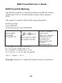
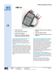
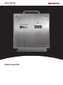
User Guide
RAE PowerPak
© Copyright 2009 Honeywell Analytics.
Ordering Replacement Parts: If you need replacement parts
please contact Honeywell Analytics Representative.
RAE PowerPak User’s Guide
Contents
1
2
3
4
5
6
7
8
9
10
11
12
13
14
15
Safety Instructions ................................................................... 4
1.1
RAE PowerPak Marking............................................ 5
1.2
Operation Area and Conditions ................................. 6
1.3
Instruction For Safe Use ............................................ 6
1.4
Use In Hazardous Areas............................................. 7
Standard Kit ............................................................................. 8
General Information................................................................. 8
Key Features ............................................................................ 9
Physical Description .............................................................. 10
LCD & LED........................................................................... 11
LED Status Indicator.............................................................. 11
LCD Status Information & Error Messages........................... 12
Installation.............................................................................. 14
Operation Instructions..................................................... 17
Connection ...................................................................... 18
Changing The RAE PowerPak........................................ .21
Charging The RAE PowerPak ......................................... 24
Troubleshooting & Repair .............................................. 27
14.1
Encapsulated Internal Battery Replacement ............ 27
14.2
Batteries And Proper Battery Disposal .................... 31
Specifications .................................................................. 32
Appendix A: Controlled Part Of RAE PowerPak (FTB1000)
Manual ................................................................... 33
3
RAE PowerPak User’s Guide
1 Safety Instructions
WARNINGS
Warning:
This instrument has not been tested in an explosive gas/air
atmosphere having an oxygen concentration greater than 21%.
Substitution of components may impair suitability for intrinsic
safety. Replace encapsulated internal batteries only in nonhazardous locations.
Warning:
Charging of the FTB 1000 by means of mains charger can only be
done in safe area and only with provided by Honeywell Analytics
Charger.
Warning:
The internal encapsulated battery units can only be exchanged with
the original provided by Honeywell Analytics battery.
4
RAE PowerPak User’s Guide
1.1
RAE PowerPak Marking
The RAE PowerPak is certified according to the IECEx scheme,
ATEX and CSA for US and Canada as protected by intrinsic
safety.
The product is marked with the following information:
RAE PowerPak
Type FTB1000.
Serial No/barcode: F032XXXXXX
IECEx DNV
09.0003X
Ex ia I/IIC T4
0575
IM1/II
1G
Ex ia I/IIC T4 DNV
09 ATEX 55726X
Cl.I Dv 1, Group
A,B,C,D T4
Only as to intrinsic
safety for use in
hazardous loc.
Intrinsically safe/
Securite
Intrinseque/Exia
Li: 0.1 µH ; Ci: 0.1 µF ; Ui: 10 V
Ii : 3.33 A; Pi: 8.8 W; Um: 11V;
Lo: 3.4 µH; Co: 100 µF; Uo : 3.6 V
Io: 3.2A; Po: 3.1 W; Lo/Ro: 20.6µH/Ω
-40º C < Tamb < +55º C
Warning: Read User’s Manual for Intrinsic Safety Precautions
5
RAE PowerPak User’s Guide
1.2
Operation Area and Conditions
Hazardous Areas classified by Zones
RAE PowerPak is intended to be used in mines susceptible to
firedamp or hazardous areas classified for zone 0, zone 1 or zone
2, within the temperature range of -40º C to +55º C, where gases of
explosion groups IIA, IIB or IIC and T4 may be present.
Hazardous Areas classified by Divisions
RAE PowerPak is intended to be used in hazardous areas
classified for Class I Div. 1 or 2, within the temperature range of
-40º C to +55º C, where gases of explosion groups A, B, C or D
and temperature class T4 may be present.
1.3
Instruction For Safe Use
Strictly follow the instructions for safe use. Application of the
RAE PowerPak requires full understanding and strict observation
of the instructions.
RAE PowerPak can be charged in hazardous areas by a
charger complying with the intrinsically safe input entity
parameters.
The RAE PowerPak can be charged outside hazardous areas by a
charger complying with the Um parameter.
The internal encapsulated battery units can only be exchanged with
the original battery provided by Honeywell Analytics, Part
Number: F03-3002-000, in a safe area or with a "hot zone" permit.
The RAE PowerPak can be connected and disconnected inside the
hazardous area.
6
RAE PowerPak User’s Guide
1.4
Use In Hazardous Areas
Equipment which is intended for use in explosive atmospheres and
which has been assessed and certified according to international
regulations may be used only under specified conditions. The
components may not be modified in any way.
The appropriate regulations for service and repair must be properly
observed during such activities.
FCC Part 15 statement and CE
This device complies with Part15 class B of the FCC rules.
Operation is subject to the following two conditions: (1) This
device may not cause harmful interference, and (2) this device
must accept any interference received, including interference that
may cause undesired operation.
7
RAE PowerPak User’s Guide
2 Standard Kit
RAE PowerPak (FTB1000), as specified with two or four
encapsulated internal batteries.
Cable for connecting MeshGuard to RAE PowerPak.
3 General Information
The RAE PowerPak (FTB-1000) is an intrinsically safe
rechargeable battery power source for use with a MeshGuard EC
or MeshGuard LEL monitor or MeshGuard Router or any other
equipment with matching entity parameters.
MeshGuard LEL and RAE PowerPak
8
RAE PowerPak User’s Guide
4 Key Features
•
•
•
•
•
•
•
•
•
Up to 4 months continuous operation before recharging, when
it contains four encapsulated internal batteries and is used with
a MeshGuard (4 months), MeshGuard LEL (25 days), or
MeshGuard Router (1.5 months)
Rugged stainless-steel enclosure
Very low-cost installation − no hardwiring involved
Very little maintenance or monitoring
Large, easy-to-read continuous display of power percentage
and charging/error messages
Bright 3-color status LED
Simple operation without switches or controls
IP-65 rated for outdoor use in harsh environments
Unit can be replaced in hazardous location
9
RAE PowerPak User’s Guide
5 Physical Description
1
Front
View
2
3
4
5
Bottom
View
6
8
9
7
1
2
3
4
5
6
7
8
9
Carrying handle
Stainless steel enclosure
Status LED
Status LCD
Protective bezel for connections
Power output port to MeshGuard
Power output dust cap
Power input from charger
Power input dust cap
10
RAE PowerPak User’s Guide
6 LCD & LED
The RAE PowerPak has a single LED and an LCD that indicates
charge, and in the case of errors any messages.
3-color LED
LCD
7 LED Status Indicator
The LED glows red, orange, or green, depending on different
status alerts it is conveying.
Color
Indication
Related LCD Message
Green
Battery (or
batteries) fully
charged.
LCD says “FULL”
Red
Battery (or
batteries)
charging.
LCD says “CHRG” (charging)
Orange
Indicates an
error. Check the
LCD for more
information.
LCD shows error code
beginning with the letters “Er”
followed by two digits
indicating the type of error.
11
RAE PowerPak User’s Guide
8 LCD Status Information & Error Messages
Error codes may appear in the LCD, indicating battery or fuse
conditions, as well as temperatures outside the normal operating
range.
Error Code Message
Er01
Er02
Er03
Er04
Er05
Er06
Er07
Er08
Er09
Er10
Er11
Er12
Er13
Er14
Er15
Battery 1 voltage too low
Battery 2 voltage too low
Battery 3 voltage too low
Battery 4 voltage too low
Battery 1 voltage too high
Battery 2 voltage too high
Battery 3 voltage too high
Battery 4 voltage too high
Battery 1 temperature too low
Battery 2 temperature too low
Battery 3 temperature too low
Battery 4 temperature too low
Wrong battery type
Wrong charger
Fuse break
Error Code
Explanation & Solution
Er01 to Er04:
The battery is not charging to full capacity. It
may need to be replaced.
The battery is overcharging, but does not send
too much power to the MeshGuard, since it
has overvoltage protection.
The battery is being charged in a location
where the temperature is below 0º C (32º F),
and therefore is charging slowly. The only
problem this presents is that the battery cannot
be fast-charged.
Er05 to Er08:
Er09 to Er12:
12
RAE PowerPak User’s Guide
The wrong type of battery has been placed in
one of the four slots. Replace it with the
correct type.
The wrong type of charger is being used. The
Correct charger provided by Honeywell
Analytics (part number F03-3014-000)
identifies itself to the RAE PowerPak.
An internal fuse has been blown. Fuses on the
main circuit board cannot be replaced. The
main circuit board must be replaced. Contact
Honeywell Analytics Technical Service.
Er13:
Er14:
Er15:
The number of batteries is indicated by the number of segments
showing in the left side of the display.
1
2
3
4
These segments correspond to the battery locations (the enclosure
is shown with its front cover removed):
2
4
3
Note: The percentage of battery
charge is relative to the capacity
of the entire number of
batteries. If there is one battery
and the reading is 75%, that
means 75% of the one battery’s
capacity. If there are multiple
batteries, 75% means 75% of
the total combined capacity.
Always refer to the number of
segments indicating the total
number of batteries.
1
13
RAE PowerPak User’s Guide
9 Installation
The RAE PowerPak is designed to be located close to a detector
such as a MeshGuard, MeshGuard LEL or MeshGuard Router. To
accommodate this, and to ensure security, both are mounted on a
steel plate, which can be attached to a wall or other flat vertical
surface.
Before attaching the steel plate to a surface, you should attach the
metal enclosure for the MeshGuard to the plate.
1. Place the MeshGuard in the steel enclosure.
2. Turn the plate and MeshGuard over.
3. Line up the hole on the back of the MeshGuard with the hole
on the plate.
4. Insert an M4x10 screw through a flat washer and locking washer,
and tighten the MeshGuard’s steel enclosure to the plate.
Front view
Rear view
Align the holes
Insert screw through flat and
locking washers and secure
14
RAE PowerPak User’s Guide
Secure the plate to a wall or other solid, flat surface by using M8size screws with flat washers and locking washers, following this
diagram. At a minimum, use four screws at the corners. (The
MeshGuard has been removed from the drawing for simplicity.)
15
RAE PowerPak User’s Guide
Next mount the RAE PowerPak onto the steel plate.
Note: Make sure the RAE PowerPak has been fully charged before
installation.
Align the RAE
PowerPak with the
rails on the metal plate
Slide the RAE PowerPak
down until it stops
Use the latch to lock the RAE PowerPak in place:
Turn the screw until it is
finger-tight – do not
overtighten or use tools
Flip the latch down to
the horizontal
position
16
RAE PowerPak User’s Guide
10 Operation Instructions
The FTB 1000 Power Pack is only to be used with provided by
Honeywell Analytics products whose entity parameters match the
entity parameters of the RAE PowerPak.
Input
Output
Fig. 1
Connections
Fig. 2
RAE PowerPak connected to the MeshGuard.
The RAE PowerPak can be connected and disconnected inside the
hazardous area.
17
RAE PowerPak User’s Guide
11 Connection
Note: The following steps must be performed outside the
hazardous area or with a “hot zone” permit.
Now connect the cable between the RAE PowerPak and the
MeshGuard.
With the MeshGuard or MeshGuard LEL securely in its housing, you can
remove the cover over the battery compartment so that you can replace the
internal battery in the MeshGuard. Use the sensor and battery
removal tool as shown.
Sensor and battery
removal tool
The connector from the RAE PowerPak screws into the MeshGuard’s
battery compartment. Bottom views of the MeshGuard in its steel
enclosure are shown in the procedure below.
1. Remove battery cover with the 3-pin end of the sensor and battery
removal tool by turning counterclockwise.
Power end
of cable
2. Lift off the cover.
3. Insert the power end of the cable
connected to the Power Pack.
18
RAE PowerPak User’s Guide
Cord to
RAE Power
Pack
4. Use the open hex end of the wrench, and with both pins mated
with the two holes on the power end, tighten by turning clockwise until it
is snug. Do not overtighten.
On the bottom of the RAE PowerPak are two dust caps that are
screwed onto the connectors:
Unscrew the one on the left by turning it counterclockwise. When
it is removed, you see the four pins of the connector.
19
PowerPak User's Guide
Screw the end of the connecting cable to the port on the bottom of
the RAE PowerPak. Do not use tools or overtighten.
FTBlOOO
IT II Clio J
20
RAE PowerPak User’s Guide
12 Changing The RAE PowerPak
1. Unscrew the battery connector from the RAE PowerPak.
2. Loosen the safety screw holding the battery latch.
21
RAE PowerPak User’s Guide
3. Raise the latch.
4. Lift up the battery and slide it off the steel plate.
22
RAE PowerPak User’s Guide
5. Mount a fully charged RAE PowerPak on the mounting
bracket.
6. Flip the latch down.
7. Tighten the safety screw.
23
RAE PowerPak User’s Guide
8. Connect the Meshguard LEL to the battery.
9. Turn on the MeshGuard LEL.
13 Charging The RAE PowerPak
Before using the RAE PowerPak and whenever the RAE
PowerPak shows a low-power reading (10% or less), you should
charge it in a safe location.
1. If the RAE PowerPak is currently in service and is attached to a
MeshGuard, follow the instructions for removing it, on page
21.
2. Remove the cap over the charging port on the bottom of the
RAE PowerPak by unscrewing it.
24
RAE PowerPak User’s Guide
3. In a safe location, connect the charging cable between the RAE
PowerPak and the Charger and connect the AC mains cord
from the Charger to an AC power plug.
4. The LED above the display should glow red and the display
should say “CHRG.” If not, check your connections and the
AC outlet.
5. When the PowerPak is fully charged, the LED glows green
and the display says “Full.”
6. Disconnect the AC mains cord from the AC power outlet.
25
RAE PowerPak User’s Guide
7. Disconnect the Charger from the RAE PowerPak.
8. Screw the cap back on over the charging port on the bottom of
the RAE PowerPak.
9. Place the RAE PowerPak on the steel mounting plate (detailed
instructions are shown on page 14).
10. Follow the insructions on page 17 to reconnect the RAE
PowerPak to the MeshGuard.
26
RAE PowerPak User’s Guide
14 Troubleshooting & Repair
The RAE PowerPak is designed to be trouble-free and require no
maintenance. However, if you see the status LED glow orange and
an error message in the display, refer to the error message table on
page 12 and take the suggested action.
14.1 Encapsulated Internal Battery Replacement
In the unlikely event that one of the encapsulated internal batteries
needs replacement, it is easy to replace them in the RAE
PowerPak. Follow these steps, and only replace an encapsulated
internal battery with a provided by Honeywell Analytics model
with the same part number (F03-3002-000).
WARNING!
Only open the RAE PowerPak enclosure and change or charge
encapsulated internal batteries in a non-hazardous location or with
a “hot zone” permit.
27
RAE PowerPak User’s Guide
1. Unscrew the four screws on the front of the enclosure.
2. Disconnect the battery’s power jumper from the main printed
circuit board.
28
RAE PowerPak User’s Guide
3. Remove the screws at both ends of the battery. These attach the
bracket that holds the battery in place.
4. Lift out the bracket and the battery.
29
RAE PowerPak User’s Guide
5. Insert a new battery and the bracket into the enclosure.
6. Replace the two screws and tighten them with a screwdriver.
Before replacing the front cover, check the display. If it is not
working, then the ribbon cable between the display and the main
circuit board might have become disconnected. Make sure it is
firmly connected to the printed circuit board and to the display
module.
30
RAE PowerPak User’s Guide
The display should indicate the correct number of batteries. If not,
check that the connector between the battery and the circuit board
is firmly connected.
7. Once everything checks out, replace the front cover and tighten
the screws.
14.2 Batteries And Proper Battery Disposal
This product may contain one or more sealed lead-acid, nickelcadmium (NiCd), nickel-metal hydride (NiMH), lithium (Li), or
lithium-ion batteries. Specific battery information is given in this
user guide. Batteries must be recycled or disposed of properly.
This symbol (crossed-out wheeled bin) indicates
separate collection of waste electrical and electronic
equipment in the EU countries. Please do not throw
the equipment into the domestic refuse. Please use the
return and collection systems available in your
country for the disposal of this product.
31
RAE PowerPak User’s Guide
15 Specifications
Display Customized LCD and red/orange/green LED
Dimensions 36.2 cm x 26 cm x 14.6 cm
(14.25″ H x 10.25″ W x 5.75″ D)
Weight 15 kg (33 lbs) with four internal batteries
Package IP-65
Output 3.3V±0.1V
Voltage
Maximum 0.33A
Output
Current
Capacity Two internal battery units: 26Ah
Four internal battery units: 52Ah
Mounting Stainless-steel wall-mount plate
Options Stainless-steel or zinced steel version
32
RAE PowerPak User’s Guide
Appendix A: Controlled Part of RAE PowerPak
(FTB1000) Manual
The scope of this document is to control the safety-related parts of
the manual, which cannot be changed without permission from the
competent body.
WARNINGS
Warning:
This instrument has not been tested in an explosive gas/air
atmosphere having an oxygen concentration greater than 21%.
Substitution of components may impair suitability for intrinsic
safety. Replace encapsulated internal batteries only in nonhazardous locations.
Warning:
Charging of the FTB 1000 by means of mains charger can only be
done in safe area and only with provided by Honeywell Analytics
Charger.
Warning:
The internal encapsulated battery units can only be exchanged with
the original provided by Honeywell Analytics battery.
33
RAE PowerPak User’s Guide
RAE PowerPak Marking
The RAE PowerPak is certified according to the IECEx scheme,
ATEX and CSA for US and Canada as protected by intrinsic
safety.
The product is marked with the following information:
RAE PowerPak
Type FTB1000.
Serial No/barcode: F032XXXXXX
IECEx DNV
09.0003X
Ex ia I/IIC T4
0575
IM1/II
1G
Ex ia I/IIC T4 DNV
09 ATEX 55726X
Cl.I Dv 1, Group
A,B,C,D T4
Only as to intrinsic
safety for use in
hazardous loc.
Intrinsically safe/
Securite
Intrinseque/Exia
Li: 0.1 µH ; Ci: 0.1 µF ; Ui: 10 V
Ii : 3.33 A; Pi: 8.8 W; Um: 11V;
Lo: 3.4 µH; Co: 100 µF; Uo : 3.6 V
Io: 3.2A; Po: 3.1 W; Lo/Ro: 20.6µH/Ω
-40º C < Tamb < +55º C
Warning: Read User’s Manual for Intrinsic Safety Precautions.
34
RAE PowerPak User’s Guide
Operation Area and Conditions
Hazardous Areas classified by Zones
RAE PowerPak is intended to be used in mines susceptible to
firedamp or hazardous areas classified for zone 0, zone 1 or zone 2,
within the temperature range of -40º C to +55º C, where gases of
explosion groups IIA, IIB or IIC and T4 may be present.
Hazardous Areas classified by Divisions
RAE PowerPak is intended to be used in hazardous areas
classified for Class I Div. 1 or 2, within the temperature range of
-40º C to +55º C, where gases of explosion groups A, B, C or D
and temperature class T4 may be present.
Instruction For Safe Use
Strictly follow the instructions for safe use. Application of the
RAE PowerPak requires full understanding and strict observation
of the instructions.
The RAE PowerPak can be charged in hazardous areas by a
charger complying with the intrinsically safe input entity
parameters.
The RAE PowerPak can be charged outside hazardous areas by a
charger complying with the Um parameter.
The internal encapsulated battery units can only be exchanged with
the original provided by Honeywell Analytics battery, in a safe area
or with a "hot zone" permit.
The RAE PowerPak can be connected and disconnected inside the
hazardous area.
35
RAE PowerPak User’s Guide
Use In Hazardous Areas
Equipment which is intended for use in explosive atmospheres and
which has been assessed and certified according to international
regulations may be used only under specified conditions. The
components may not be modified in any way.
The appropriate regulations for service and repair must be properly
observed during such activities.
36
Find out more
www.honeywellanalytics.com
Contact Honeywell Analytics:
Europe, Middle East, Africa
Life Safety Distribution AG
Javastrasse 2
8604 Hegnau
Switzerland
Tel: +41 (0)44 943 4300
Fax: +41 (0)44 943 4398
[email protected]
Customer Service:
Tel: +800 333 222 44 (Freephone number)
Tel: +41 44 943 4380 (Alternative number)
Fax: +800 333 222 55
Middle East Tel: +971 4 450 5800 (Fixed Gas Detection)
Middle East Tel: +971 4 450 5852 (Portable Gas Detection)
India Tel: +91 124 4752700
Americas
Honeywell Analytics Inc.
405 Barclay Blvd.
Lincolnshire, IL 60069
USA
Tel: +1 847 955 8200
Toll free: +1 800 538 0363
Fax: +1 847 955 8210
[email protected]
Asia Pacific
Honeywell Analytics Asia Pacific
#701 Kolon Science Valley (1)
43 Digital-Ro 34-Gil, Guro-Gu
Seoul 152-729
Korea
Tel: +82 (0)2 6909 0300
Fax: +82 (0)2 2025 0328
India Tel: +91 124 4752700
[email protected]
Technical Services
EMEAI: [email protected]
US:
[email protected]
AP:
[email protected]
www.honeywell.com
Please Note:
While every effort has been made to ensure accuracy in this publication,
no responsibility can be accepted for errors or omissions. Data may change,
as well as legislation and you are strongly advised to obtain copies of the most
recently issued regulations, standards and guidelines. This publication is not
intended to form the basis of a contract.
13428_REV A_07/2009
H_MAN0977_EMEAI
© 2014 Honeywell Analytics