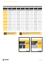
1
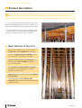
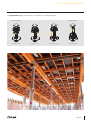
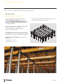
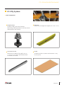
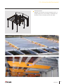
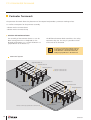
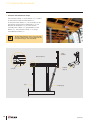
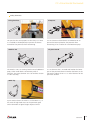
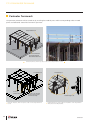
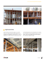
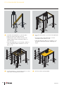
CC-4 Horizontal Formwork
Light, safe and fast recoverable formwork with excellent finishes
Construcción
IMPORTANT:
Any safety provisions as directed by the appropriate governing
agencies must be observed when using our products.
The pictures in this document are snapshots of situations at different
stages of assembly, and therefore are not complete images. For the
purpose of safety, they should not be deemed as definitive.
All of the indications regarding safety and operations contained in
this document, and the data on stress and loads should be
respected. ULMA Construcción’s Technical Department must be
consulted anytime that field changes alter our equipment
installation drawings.
The loads featured in this document, related to the basic elements
of the product, are approximate.
Our equipment is designed to work with accessories and elements
made by our company only. Combining such equipment with other
systems is not only dangerous but also voids any or all our
warrantees.
The company reserves the right to introduce any modifications
deemed necessary for the technical development of the product.
All rights reserved.
Neither all nor part of this document may be reproduced or
transmitted in any way by any electronic or mechanical procedure,
including photocopy, magnetic recording or any other form of
information storage or retrieval system without the written
permission of ULMA Construcción.
CC-4 Horizontal Formwork
4
10
28
39
50
51
56
60
Product description
Solutions
System features
Assembly, use and disassembly
Conditions of handling and maintenance
Components and accessories
ULMA Construcción addresses
Our products
Safety note
Control note
Warning note
Information note
CC-4 Horizontal Formwork
Product description
Light and versatile system with excellent exposed concrete finishes
CC-4 is a recoverable horizontal formwork system for
both solid and lightened slabs with a very good finish,
focused on residential and non-residential construction.
It is characterised by its fast assembly and disassembly,
as well as worker’s safety during the handling process.
Most of its components are made in aluminium.
Formwork detail
Main features of the CC-4
Most of the components are manufactured in
aluminium, providing lightness to the system.
It allows the grid’s previous assembly and the
later placement of the panels or plywood.
Direction of the beams can be changed in any
position using the 90º assembly, making the
system really flexible.
The formwork surface of panels or boards,
depending on the selected system, provides
excellent concrete finishes.
Only one remaining element (Drophead) together
with the prop.
The striking system allows material to be
recovered without falling to the floor, contributing
to worker’s safety.
CC-4 Panel System
4
Construcción
CC-4 Horizontal Formwork
The Drophead CC allows the materials safe recovery by a simple operation.
Formwork position
Hitting the wedge
Stripping position
Turning the wedge
Lowering the wedge
Lowering the grid
5
Construcción
CC-4 Horizontal Formwork
The CC-4 System is designed to allow different types of assembly:
CC-4 Panel System:
Optimal efficiency for large areas
System for solid slabs, primarily focused to
non-residential construction of large areas,
where the geometry and the span between
columns are regular and the finish requirements
are highly demanding.
The system has elements for infilling on columns and
walls, perimeter protection and safety.
The CC-4 Panel System is composed of Dropheads,
Beams, Transversal CC TE and Panels.
The shuttering face is composed by Panels,
Transversals and Dropheads.
The Drophead enables the recovery of all the parts
that belong to the system, except the prop and the
Head itself, without any parts falling to the ground.
Repercussion of 0.29 props/m2, with the basic
dimensions:
• Panel de 1.5 x 0.75 m.
• Retícula de 2.32 x 1.5 m.
6
Construcción
CC-4 Horizontal Formwork
CC-4 Ply System:
Excellent finish for any type of geometry
System for slabs primarily focused to residential
and non-residential construction, with complex
geometries and very demanding finish
requirements.
System with Dropheads, Beams and Transversals
CC TR, forming a grid to place the shuttering
boards.
Allows to recover the Beams, Transversals and
Boards not trapped by the drophead.
The system has accessories for infilling on columns
and walls, perimeter protection and safety.
This system is characterized by its high versatility.
7
Construcción
CC-4 Horizontal Formwork
CC-4 Panel System
Basic components
The basic components of this system are:
Drophead CC
Beam CC
It has a dropping system which facilitates
dismantling, enabling Panels, Beams and
Transversals to descend. This head and the prop
are the only remaining elements.
It defines the length of the grid, which can be 2.32
or 1.57 m long.
Transversal CC TE
Panel CC
It establishes the width of the grid, which can be
1.5 or 0.75 m between axes. It is always in
contact with the concrete. It is designed for the
joint with the panel to be watertight.
The shuttering face is a phenolic plywood fixed into
the frame. It includes some hollows on the sides, as
handles, to facilitate its manipulation.
8
Construcción
CC-4 Horizontal Formwork
CC-4 Ply System
Basic components
Drophead CCT
Includes a drop system that facilitates
dismantling, allowing the Beams and Transversals
to descend for their recovery.
Beam CC
Determines the length of the grid (2.32 m or 1.57 m).
Transversal CC TR
Board
Determines the width of the grid (2.075 m,
1.5 m or 0.75 m) and its plastic block allows
the board to be nailed.
Shuttering surface in contact with concrete. It may
be of any size.
9
Construcción
CC-4 Horizontal Formwork
Solutions
A world of geometrical possibilities
grafsystem
Application software
This software, developed by ULMA Construcción, offers
the solution for any construction project applying all the
products in ULMA’s portfolio.
With the project drawings, ULMA Construcción
Technical Department can solve every construction job,
when building vertical or horizontal structures.
grafsystem obtains, quickly and easily, the
assembly drawings and a detailed material’s
budget for each project.
In short, by simply entering the desired structure
geometry, this software provides the best solution for
any case.
Jobsite geometry
List of materials – budget
Solution – CC-4 Panel System
Solution – CC-4 Ply System
10
Construcción
CC-4 Horizontal Formwork
90º assembly
The direction of the formwork can be changed
according to need, providing versatility and makes
infilling simpler. Beams CC, Transversals CC TE,
Transversals CC TR and Panels CC can be placed on the
lateral profile of the Beams CC, Beams CC W and
Perimeter Beam CC.
For further information refer to Perimeter
formwork section.
The 90º assembly, enables an optimal distribution
of the formwork, to improve infilling on columns
or hollows, as well as to minimize the infilling on
straight or irregular walls.
In every 90º assembly, an additional prop has to be
installed to support the beam projected 90º. Using:
• Head CC FD for 90º assemblies on the basic grid.
• Clamp CC or Tie piece CC LD for 90º assemblies in
the perimeter solution, which also prevents the Beam
from overturning.
CC-4 Ply System
CC-4 Panel System
Hollow part to install bulkheads
Panels CC
90º Assembly
support
Beams CC
Beams CC
Head CC FD
Basic grid 90º assembly
Additional shoring
for 90º assembly
Head CC FD
Additional shoring
for 90º assembly
Basic grid 90º assembly
11
Construcción
CC-4 Horizontal Formwork
Infillings
Infilling on column
The optimal situation for infilling on columns is when the layout of the formwork allows to have the columns
inside the Beam CC and Transversal CC TE or CC TR grid.
Transversals CC TR are used as a support to nail 21 mm thickness plywood on top.
CC-4 Panel System
Column inside the grid
Infilling is done with Transversals CC TR and
21mm thickness plywood when columns
dimensions allow it.
If the column’s geometry allows it, a collar can be
installed using the Beam CC W to support the
Transversals CC TR. To minimise the use of infilling
plywood, Panel CC 1.5 x 0.375 is available.
21 mm Plywood
Transversal CC TE
Beam CC W
Transversal CC TE
Panel CC
Transversal CC TR
Drophead CC
Drophead CC
Panel CC 1.5 x 0.375
Beam CC
21 mm Plywood
Beam CC
Transversal CC TR
If the structure elements coincide with the
column, there are two options:
• Carry out a local formwork offset.
• Assemble a narrower local grid.
12
Construcción
CC-4 Horizontal Formwork
Column in a panel
Column in two Panels
Use Transversals CC TR 1.5 on both sides of the column
to nail the infilling plywood properly (21 mm-thick
plywood).
Use Panels CC 1.5 x 0.375 (narrow panel) to reduce the
infilling surface until it is equivalent to one single panel.
Column that coincides with the Beam CC
Use the Beam CC W 1.5 for the local column off-set.
Assembly begins in the area of capitals
13
Construcción
CC-4 Horizontal Formwork
CC-4 Ply System
The infilling on column is done in a simple
manner, since the Transversals CC TR can be
placed at any point of the beam.
Transversal CC TR 1.5
Board
Depending on the dimension of the column,
Beams CC W can be used to place additional
Transversals CC TR.
The flexibility and versatility of the CC-4 Ply
Horizontal Formwork allows completing the
column infillings quickly and easily.
Drophead CCT
Beam CC
14
Construcción
CC-4 Horizontal Formwork
Infilling on walls
CC-4 Panel System
Infilling on walls in the direction of the Beams CC
The formwork should be as close as possible to
the wall. Changing the direction of the beams
(90º assembly) may improve the infillings on walls.
The CC Infilling support installed on the Beam CC
provides support to install Transversals CC TR
parallel to the Beam and, facilitate the infilling on
walls, providing support for the 21 mm Infilling
plywood.
CC Infilling supports
Fixed on the beam profile
Beam CC
21 mm Plywood
Transversal CC TR
Infilling support CC
Guide along the beam
Insert the hook in this part
of the beam and guide it
to the right position.
Transversal CC TE 1.5
15
Construcción
CC-4 Horizontal Formwork
Infilling on walls in the perpendicular direction of the Beams CC
The Dropheads should also be installed as close as
possible to the wall, combining different lengths
of the Beam CC.
Infilling plywood
In the last grid, close to the wall, replace the
Dropheads CC with Dropheads CCT, and the
Transversals CC TE with the Transversals CC TR to
support the 21mm Infilling plywood.
This solution is preferable because the
infilling is easier.
Use the Drophead CCT and Transversal CC TR to nail
the 21 mm plywood for infilling on walls.
Transversal CC TR
Drophead CCT
Drophead CCT
Transversal CC TR
The Timber beams VM 20 can be used in both the
CC-4 Panel and the CC-4 Ply Systems to support the
Infilling board.
Timber beam VM 20
16
Construcción
CC-4 Horizontal Formwork
CC-4 Ply System
Regardless of whether the union between walls is a
straight angle or not, the infilling is facilitated since
the beams can be rested on top of each other.
17
Construcción
CC-4 Horizontal Formwork
Perimeter formwork
The perimeter formwork allows the placement of the stopend and provides a perimeter working surface.
CC-4 offers two options for the perimeter assembly:
- Solution with a Perimeter beam
- Solution with a Perimeter clamp
Solution with Perimeter beam
The assembly of the Perimeter beams CC can be
done starting from the CC Dropheads (in the
direction of the Beams CC), or from the Beams CC
(perpendicular to the Beams CC).
The difference between both assemblies is the safety
accessories they use. This way it is possible to cover
all the area to be shuttered.
In order to prevent the Perimeter beam CC
from tipping over, use the Fixing hook CC
in the direction of the Beams CC and the
Clamp CC perpendicular to the Beams CC.
CC-4 Panel System
Supporting frame CC
Transversal CC TE
Safety handrail S-V
Perimeter formwork in the
direction of the Beams CC
Perimeter beam CC
Supporting frame CC
Transversal CC TE
Supporting frame CC
Safety handrail S-V
Supporting frame CC
Perimeter beam CC
Perimeter formwork perpendicular to the Beams CC
18
Construcción
CC-4 Horizontal Formwork
Clamp CC
Supporting frame CC
Use of the Perimeter beam CC with the Clamp CC and the Supporting
frame CC to solve the perimeter area
The perimeter formwork with Perimeter
beams CC will always project less than a
panel and a half, i.e., no more than 1.1 m.
CC-4 Ply System
Perimeter formwork solution with Perimeter beam CC in the CC-4 Ply System
19
Construcción
CC-4 Horizontal Formwork
Solution with Perimeter clamp
The Perimeter clamp CC on the Beam CC is used as
an alternative to the Perimeter beam CC.
As with Perimeter beams CC, the assembly can be
carried out starting from a Drophead CC (in the
direction of the Beams CC), or from the 90º
assembly from a Beam CC (perpendicular to the
Beams CC). The Perimeter clamp CC is always
assembled on a Beam CC.
The maximum distances at the end of the slab
are 0.75 m (when using a 2.32 m Beam CC) and
0.5 m (when using a 1.57 m Beam CC).
Safety
handrail
Beam CC 2.32/1.5
Perimeter
clamp CC
Clamp CC
Prop
Inclined prop
20
Construcción
CC-4 Horizontal Formwork
Safety elements
Fixing hook CC
This part has the same purpose as the Clamp CC when
it is installed on the drophead, to prevent the beams
situated on the perimeter from overturning.
Head CC FD
The Head CC FD is an auxiliary head to install additional
props, either under beams or between panels if
necessary. The most common use is to reinforce a beam
in a 90º assembly.
Clamp CC
It is an element to fasten beams assembled at 90º to
prevent the beams placed on the perimeter from
overturning. It has a socket for a reinforcement prop.
Tie piece CC LD
It is an element that is inserted and fixed on the lower
part of the perimeter beam to anchor the beam to the
slab with a cable or chain. It is a useful element for the
perimeter solution.
Wind clip
A part used to fasten the Panel CC to the Beam CC, in
the event of high wind stress on the perimeter grids
and in formworks of great height subject to wind.
21
Construcción
CC-4 Horizontal Formwork
Perimeter formwork
The perimeter protection will be carried out by installing the Handrail posts and the corresponding tubes or wood
planks and toeboards around the formwork’s perimeter.
Safety handrail S-V
Perimeter beam CC
Tube for the Handrail
post incorporated in
the Perimeter beam CC
Perimeter beam CC, which incorporates a tube for the Safety handrail on its end
S-V Handrail post
S-V Handrail post
Beam CC
Perimeter Clamp CC
Housing for the handrail
post incorporated in the
CC Perimeter clamp
Perimeter clamp CC, which incorporates a tube for the Safety handrail on
its end
Handrail support CC
Handrail support CC, which enables the installation of the Safety handrail
when placed on the Drophead CC
22
Construcción
CC-4 Horizontal Formwork
Perimeter railing to provide safety during the execution process
Lightened slabs
Lightened slabs can be made using the CC-4 Panel
System. To avoid punching the lightening blocks, the
Drophead CCT and Supporting transversals are used,
instead of the Drophead CC and Transversal CC TE. The
Drophead CCT allows the beams and the panels to be
recovered keeping them from falling when the concrete
has reached the minimum required resistance. Once the
head is stripped, the Supporting transversal and the
prop remain as supporting elements until the concrete
has reached the required strength.
Supporting frame CC
23
Construcción
CC-4 Horizontal Formwork
Jobsite references
Las Arenas Commercial Center, Barcelona (Spain)
Fira Towers, Barcelona (Spain)
24
Construcción
CC-4 Horizontal Formwork
S and V Tower, Madrid (Spain)
S and V Tower, Madrid (Spain)
25
Construcción
CC-4 Horizontal Formwork
Castelnuovo del Garda Commercial Center, Verona (Italy)
Woodstock Hospital (Canada)
Torch Tower, Dubai (UAE)
26
Construcción
CC-4 Horizontal Formwork
Torrelodones Commercial Center, Madrid (Spain)
Forum Coimbra (Portugal)
Renoma Commercial Center, Wrocław (Poland)
27
Construcción
CC-4 Horizontal Formwork
System features
CC-4 Panel System
Grids
Depending on the needs, the following grids can be assembled with the CC-4 Panel System.
2.32 m
1.57 m
Drophead CC
17
m
1.5 m
1.5 m
6m
2.7
2.
Transversal CC TE 1.5
Transversal CC TE 1.5
Panel CC 1.5 x 0.75
Beam CC 1.57
Beam CC 2.32
2.32 x 1.5 Grid
1.57 x 1.5 Grid
2.32 m
1.57 m
Transversal CC TE 0.75
4m
1.7
Beam CC 2.32
Panel CC 1.5 x 0.75
0.75 m
4m
2.4
0.75 m
Panel CC 0.75 x 0.75
Beam CC 1.57
Transversal CC TE 0.75
Drophead CC
1.57 x 0.75 Grid
The maximum slab thickness reached by the different
grids depends on the size of the grid and the finish
quality required. To achieve this, the beam and panel
deflections should be added and verified that they
are smaller than the maximum deflection for the
required finnish quality. Nevertheless, it has to be
verified that the loads applied to each element are
not higher than their working load. Finally, check the
shoring, which depends on the type of props that
are used and the clear height.
2.32 m
Reinforcement prop
Drophead CC
6m
2.7
1.5 m
2.32 x 0.75 Grid
Transversal CC TE 1.5
Panel CC 1.5 x 0.75
Beam CC 2.32
2.32 x 1.5 Grid with reinforced beam
The formwork system can be used up to
90 cm slab thickness.
28
Construcción
CC-4 Horizontal Formwork
Maximum slab thicknesses
The following maximum slab thicknesses are established for the different grids:
GRID (m)
MAXIMUM SLAB
THICKNESS (cm)
2.32 x 1.5
40
1.57 x 1.5
60
2.32 x 1.5 Reinforced beam
60
2.32 x 0.75
90
1.57 x 0.75
90
CC-4 Panel System’s maximun slabs
CC-4 Panel System in dismantling phase
29
Construcción
CC-4 Horizontal Formwork
Loads transferred to the prop
The following table lists the loads transferred to the prop, depending on the slab’s thickness and the grid:
GRIDS
BEAM 2.32
Slab thickness
(cm)
BEAM 1.57
1.50 m GRID
0.75 m GRID
1.50 m GRID
0.75 m GRID
PROP LOAD
PROP LOAD (kN)
(kN) (Reinforced beam*)
PROP LOAD
(kN)
PROP LOAD
(kN)
PROP LOAD
(kN)
5
9.60
4.80
6.50
3.20
10
13.90
7.00
9.40
4.70
15
18.30
9.10
12.40
6.20
20
22.60
11.30
15.30
7.70
25
27.00
13.50
18.30
9.10
30
31.30
15.70
21.20
10.60
35
36.10
18.10
24.40
12.20
40
40.90
25.56
20.40
27.70
13.80
45
28.55
22.80
30.90
15.50
50
31.54
25.20
34.10
17.10
55
34.53
27.60
37.40
18.70
60
37.52
30.00
40.60
20.30
65
32.40
21.90
70
34.80
23.60
75
37.00
25.00
80
39.20
26.50
85
41.30
28.00
90
43.50
29.40
Attention should be paid to the load that the
remaining support prop should bear upon the
removal of the extra prop. It is necessary to verify
this load.
Props shall be used correctly, respecting load
limits, plumbed and with a stable support.
30
Construcción
CC-4 Horizontal Formwork
CC-4 Ply System
Grids
Depending on the selection of the Beam CC or the Beam CC W, and the size of the Transversal CC TR and the
distance between them, different grids are obtained.
Board
Transversal CC TR
Transversal CC TR
Drophead CCT
Beam CC
Beam CC ó CCW
SOLUTION WITH BEAM CC
Transversal CC TR 2.075
Beam CC
2.32
Beam CC
1.57
2.32 x 1.5
Transversal CC TR 0.75
2.32 x 0.75
Transversal CC TR 2.075
1.57 x 2.075
Transversal CC TR 1.5
1.57 x 1.5
Transversal CC TR 0.75
1.57 x 0.75
Transversal CC TR 2.075
Beam CCW
1.5
2.32 x 2.075
Transversal CC TR 1.5
SOLUTION WITH BEAM CC W
Beam CCW
2.075
GRID
GRID
2.075 x 2.075
Transversal CC TR 1.5
2.075 x 1.5
Transversal CC TR 0.75
2.075 x 0.75
Transversal CC TR 2.075
1.5 x 2.075
Transversal CC TR 1.5
1.5 x 1.5
Transversal CC TR 0.75
1.5 x 0.75
CC-4 Ply System Grid
31
Construcción
CC-4 Horizontal Formwork
The maximum slab thickness feasible with each grid
depends on the grid dimensions, the board used and
the desired finnish quality.
Maximum slab thicknesses
Below is a list of the maximum slab thicknesses with the Beam CC 2.32 and Transversals CC TR, with various
distances between them and different boards:
Distance between
Transversals
Grid
(mm)
Type of board
BIRCH 15 mm
BETO 18 mm
BETO 21 mm
Beam CC 2.32 x Transversal CC TR 2.075
28
31
31
Beam CC 2.32 x Transversal CC TR 1.5
37
44
44
Beam CC 2.32 x Transversal CC TR 0.75
51
52
75
Beam CC 2.32 x Transversal CC TR 2.075
31
31
31
Beam CC 2.32 x Transversal CC TR 1.5
44
44
44
Beam CC 2.32 x Transversal CC TR 0.75
80
80
90
580
464
Maximum slab thickness (cm)
32
Construcción
CC-4 Horizontal Formwork
Working load tables for CC-4 Ply System
As an example, the following table includes the finish quality for
each slab thickness with the Beam CC 2.32 and different Transversals
CC TR with a separation of 580 mm between them, according to
DIN 18202, using different types of boards.
Distance
between 580 mm
Transversal CC TR 2.075
Transversals
CC TR
BIRCH 15 mm BETO 18 mm BETO 21 mm
Slab thickness
(cm)
5
10
11
12
13
14
15
16
17
18
19
20
21
22
23
24
25
26
27
28
29
30
31
32
33
34
35
36
37
38
39
40
41
42
43
44
45
46
47
48
49
50
51
52
53
54
55
60
61
62
63
64
65
70
75
TOTAL
deflection
TOTAL
deflection
TOTAL
deflection
7
7
7
6
6
6
5
5
5
Restricted
Restricted Restricted
Colour
Finish in accordance with DIN 18202
7
Group 7
6
Group 6
5
Group 5
Restricted
Load restrictions
BEAM CC 2.32
Transversal CC TR 1.5
Prop Load
(kN)
13.24
19.26
20.46
21.66
22.87
24.07
25.27
26.48
27.68
28.88
30.09
31.29
32.49
33.70
34.90
36.11
37.31
38.51
39.72
40.92
42.12
43.33
44.65
45.97
47.30
48.62
49.95
51.27
52.59
53.92
55.24
56.56
57.89
59.21
60.54
61.86
63.18
64.51
65.83
67.16
68.48
69.80
71.13
72.45
73.77
75.10
76.42
83.04
84.37
85.69
87.01
88.34
89.66
96.28
102.30
BIRCH 15 mm BETO 18 mm BETO 21 mm
TOTAL
deflection
TOTAL
deflection
TOTAL
deflection
7
7
7
6
6
6
5
5
5
Restricted
Restricted Restricted
Transversal CC TR 0.75
Prop Load
(kN)
9.57
13.92
14.79
15.66
16.53
17.40
18.27
19.14
20.01
20.88
21.75
22.62
23.49
24.36
25.23
26.10
26.97
27.84
28.71
29.58
30.45
31.32
32.28
33.23
34.19
35.15
36.11
37.06
38.02
38.98
39.93
40.89
41.85
42.80
43.76
44.72
45.68
46.63
47.59
48.55
49.50
50.46
51.42
52.37
53.33
54.29
55.25
60.03
60.99
61.94
62.90
63.86
64.82
69.60
73.95
BIRCH 15 mm BETO 18 mm BETO 21 mm
TOTAL
deflection
TOTAL
deflection
TOTAL
deflection
7
7
6
7
6
5
5
Restricted
6
Restricted
5
Prop Load
(kN)
4.79
6.96
7.40
7.83
8.27
8.70
9.14
9.57
10.01
10.44
10.88
11.31
11.75
12.18
12.62
13.05
13.49
13.92
14.36
14.79
15.23
15.66
16.14
16.62
17.10
17.57
18.05
18.53
19.01
19.49
19.97
20.45
20.92
21.40
21.88
22.36
22.84
23.32
23.79
24.27
24.75
25.23
25.71
26.19
26.67
27.14
27.62
30.02
30.49
30.97
31.45
31.93
32.41
34.80
36.98
33
Construcción
CC-4 Horizontal Formwork
To check the slab thicknesses for other
layouts and the prop loads, refer to the
CC-4 Ply User’s Manual
Grid assembly for CC-4 Ply System
Boards assembly for CC-4 Ply System
34
Construcción
CC-4 Horizontal Formwork
Prop working loads
Working loads for EP Props with CC-4
The following table shows the working loads obtained by calculation according to EN 1065, when EP Props are
used with CC-4 Formwork.
Prop
C25
Inner Tube
h (m)
Above
C+D30
Below
1.48 - 2.50 m
Above
C+D35
Below
1.72 - 3.00 m
Above
C+D40
Below
1.98 - 3.50 m
Above
Below
2.22 - 4.00 m
5.00
4.90
4.80
4.70
4.60
4.50
4.40
4.30
4.20
4.10
4.00
23.20
27.10
3.90
24.90
29.30
3.80
26.70
31.70
3.70
28.50
34.30
3.60
30.50
37.20
3.50
29.80
34.70
32.60
40.50
3.40
32.30
38.10
35.00
43.05
3.30
34.90
41.90
37.60
43.05
3.20
37.70
43.05
40.50
43.05
3.10
40.80
43.05
42.30
43.05
3.00
23.30
28.20
43.05
43.05
43.05
43.05
2.90
25.30
31.30
43.05
43.05
43.05
43.05
2.80
27.50
34.80
43.05
43.05
43.05
43.05
2.70
29.90
38.90
43.05
43.05
43.05
43.05
2.60
32.50
43.05
43.05
43.05
43.05
43.05
2.50
32.30
36.30
34.20
43.05
43.05
43.05
43.05
43.05
2.40
35.80
41.10
35.50
43.05
43.05
43.05
43.05
43.05
2.30
37.80
43.05
37.10
43.05
43.05
43.05
43.05
43.05
2.20
39.10
43.05
39.20
43.05
43.05
43.05
2.10
40.20
43.05
42.20
43.05
43.05
43.05
2.00
41.70
43.05
43.05
43.05
43.05
43.05
1.90
43.05
43.05
43.05
43.05
1.80
43.05
43.05
43.05
43.05
1.70
43.05
43.05
1.60
43.05
43.05
1.50
43.05
43.05
Inner tube below ALWAYS with
screwed head.
35
Construcción
CC-4 Horizontal Formwork
Prop
C+D45
Inner Tube
h (m)
Above
C+D50
Below
2.48 - 4.50 m
Above
C+E30
Below
2.73 - 5.00 m
5.00
23.70
26.40
4.90
25.10
28.40
4.80
26.60
30.30
4.70
28.10
32.20
4.60
Above
C+E40
Below
1.71 - 3.00 m
Above
Below
2.22 - 4.00 m
29.70
34.30
4.50
28.90
32.60
31.40
36.60
4.40
30.80
35.00
33.20
39.10
4.30
32.80
37.60
35.20
41.90
4.20
35.00
40.30
37.40
43.05
4.10
37.20
43.40
39.80
43.05
4.00
39.70
43.05
42.40
43.05
36.00
40.50
3.90
42.40
43.05
43.05
43.05
38.80
43.05
3.80
43.05
43.05
43.05
43.05
41.80
43.05
3.70
43.05
43.05
43.05
43.05
43.05
43.05
3.60
43.05
43.05
43.05
43.05
43.05
43.05
3.50
43.05
43.05
43.05
43.05
43.05
43.05
3.40
43.05
43.05
43.05
43.05
43.05
43.05
3.30
43.05
43.05
43.05
43.05
43.05
43.05
3.20
43.05
43.05
43.05
43.05
43.05
43.05
3.10
43.05
43.05
43.05
43.05
43.05
43.05
3.00
43.05
43.05
43.05
43.05
39.70
43.05
43.05
43.05
2.90
43.05
43.05
43.05
43.05
43.05
43.05
43.05
43.05
2.80
43.05
43.05
43.05
43.05
43.05
43.05
43.05
43.05
2.70
43.05
43.05
43.05
43.05
43.05
43.05
2.60
43.05
43.05
43.05
43.05
43.05
43.05
2.50
43.05
43.05
43.05
43.05
43.05
43.05
2.40
43.05
43.05
43.05
43.05
2.30
43.05
43.05
43.05
43.05
2.20
43.05
43.05
2.10
43.05
43.05
2.00
43.05
43.05
1.90
43.05
43.05
1.80
43.05
43.05
1.70
1.60
1.50
Inner tube below ALWAYS with
screwed head.
36
Construcción
CC-4 Horizontal Formwork
Working loads for ALUPROP Prop
The following table lists the working loads (KN) of the ALUPROP Prop for each height. The most appropriate
one should be selected for each case depending on the load to carry and the height to cover.
Inner Tube
h (m)
Above
Below
1.65 - 2.80 m
Above
Below
2.20 - 3.70 m
Above
Below
3.30 - 4.80 m
1.65
151.20
106.90
1.70
148.60
106.90
1.80
143.40
106.90
1.90
138.20
106.60
1.95
135.50
106.20
2.00
132.80
105.70
2.10
127.30
104.40
2.20
121.70
102.70
132.40
115.50
2.30
116.10
100.50
126.70
110.80
2.40
110.30
97.90
121.00
106.30
2.50
104.40
94.80
115.50
101.90
2.60
98.50
91.40
110.10
97.70
2.70
92.40
87.40
104.70
93.60
2.80
86.30
83.10
99.40
89.70
2.90
94.20
86.00
3.00
89.10
82.40
3.10
84.10
79.00
3.20
79.10
75.70
3.30
74.30
72.60
89.60
75.70
3,40
69.50
69.70
85.20
73.40
3,50
64.80
66.90
80.90
71.20
3,60
60.20
64.30
76.80
68.90
3,70
55.70
61.80
72.80
66.70
3,80
69.00
64.40
3,90
65.30
62.20
4,00
61.80
59.90
4,10
58.40
57.60
4,20
55.20
55.30
4,30
52.10
53.00
4,40
49.20
50.70
This data is for new Props. Props
should be used plumbed and
with centred vertical load.
Above
Below
4.50 - 6.00 m
The Props can be used with the Inner tube above or below,
as long as it is taken into consideration that the load
capacity is different for each case.
37
Construcción
CC-4 Horizontal Formwork
Inner Tube
h (m)
Above
Below
1.65 - 2.80 m
Above
Below
2.20 - 3.70 m
Above
Below
3.30 - 4.80 m
Above
Below
4.50 - 6.00 m
4.50
46.40
48.40
51.90
47.10
4.60
43.80
46.10
50.10
45.70
4.70
41.30
43.70
48.40
44.20
4.80
38.90
41.40
46.60
42.80
4.90
44.80
41.40
5.00
42.90
40.00
5.10
41.10
38.60
5.20
39.20
37.20
5.30
37.40
35.80
5.40
35.50
34.40
5.50
33.60
33.00
5.60
31.70
31.60
5.70
29.80
30.20
5.80
27.80
28.80
5.83
27.30
28.40
5.90
25.90
27.50
6.00
23.90
26.10
This data is for new Props. Props
should be used plumbed and
with centred vertical load.
The Props can be used with the Inner tube above or below, as
long as it is taken into consideration that the load capacity is
different for each case.
For further information refer to CC-4 Panel and CC-4 Ply Horizontal Formwork User’s Manual
38
Construcción
CC-4 Horizontal Formwork
Assembly, use and disassembly
Lightness, safety and speed
Assembly instructions
CC-4 Panel System
The basic grid is formed by Beams CC and
Transversals CC TE, supported by Dropheads CC.
Panels CC are supported by the beams.
Panel CC
The parts in contact with the concrete are: Panels
CC, Transversals CC TE and Dropheads CC.
Drophead CC
The only remaining element is the Drophead CC,
with its corresponding prop.
Beam CC
Transversal CC TE
For further information refer
to CC-4 Panel Horizontal
Formwork User’s Manual
1 • Assemble the Dropheads CC on the props.
• Following the layout, stabilise the prop with
tripods round a column and hang a Beam CC
from the dropheads.
Layout before assembling the grid
Verify the correct fitting of the Head.
39
Construcción
CC-4 Horizontal Formwork
2 • Install two props with Dropheads CC and assemble the Transversals CC TE.
• Close the grid with a Beam CC and place it around the column following the layout.
3 • Install the Panels CC and Transversals CC TR to proceed with the infilling on the column.
• Infill the column with 21 mm plywood.
40
Construcción
CC-4 Horizontal Formwork
4 • Assemble the grid in the direction of the
Assemble the grid
Transversal and level it.
5 • Install the Panels CC and carry out the infilling on
Beams CC assembly
columns.
• Hang Beams CC to continue the assembly in the
direction of the main beam. Level the grid.
41
Construcción
CC-4 Horizontal Formwork
From mobile towers
The beams and panels are designed so as all the
panels in the same grid can be placed without
moving the mobile tower.
With lifelines
It enables the installation of several panels from a
fixed point of the working platform, because panels
slide along the beams until they stop against the
transversals.
With nets under the formwork
Simple net hook
Detail of attaching
the net to the
Drophead CC
6 • Assemble the grid and the Panels CC
Mounting the Panels CC from
lifting platforms
42
Construcción
CC-4 Horizontal Formwork
7 • Finish assembling the Panels CC and the infilling
Detail of Handrail post assembly
on columns.
• Install the Safety handrails and Toe boards, always
while wearing a harness that is attached to a
lifeline.
DISMANTILING: In normal setting conditions,
recoverable material can be removed after
three days.
CC-4 Ply System
The basic grid is formed by Beams CC and
Transversals CC TR, which rest on the Dropheads
CCT. The Transversals and the heads are the
elements supporting the board.
For further information refer to
CC-4 Ply Horizontal Formwork
User’s Manual
43
Construcción
CC-4 Horizontal Formwork
1 • Assemble the Dropheads CCT on the props.
• Verify the correct fitting of the head.
• Following the layout, stabilise the prop with
tripods round a column and hang a Beam CC
from the head.
• Place the Drophead CCT on the prop, stabilise it
with a tripod and mount the Beam CC or the
Beam CC W.
3 • Install the Beams CC W and Transversals CC TR to
2 • Hang two Transversals CC TR from the Dropheads
CCT.
• Install two props with Dropheads CCT and
assemble the Transversals CC TR.
• Close the grid with a Beam CC or Beam CC W
and place it around the column following the
layout.
4 • Infill the column with plywood.
carry out the infilling on the column.
44
Construcción
CC-4 Horizontal Formwork
5 • Assemble the grid in the direction of the
Grid assembly for CC-4 Ply System
Transversal and level it.
6 • Carry out the infilling on columns.
Perimeter beam CC assembly
• Place Beams CC or Beams CC W to continue the
assembly in the longitudinal direction. Level the grid.
45
Construcción
CC-4 Horizontal Formwork
From mobile tower
With lifelines
With nets under the formwork
7 • Assemble the boards.
8 • Finish assembling the boards and carry out
the infilling on columns.
• Install the Safety handrails and Toe boards,
always wearing a harness attached to a
lifeline.
46
Construcción
CC-4 Horizontal Formwork
Disassembly instructions
CC-4 Panel System
1 • Move the Safety handrail (Handrail, Handrail
support and Toe boards) to the plastic
handrail support or replace it with another
type of perimeter protection.
• Remove the additional props for infilling or
90º assembly.
2 • Strike the wedges on the Dropheads CC, except
the ones on the Perimeter beams.
• The wedge drops 150 mm and then the Beams,
Transversals and Panels drop too.
47
Construcción
CC-4 Horizontal Formwork
3 • Remove the Panels.
4 • Remove the Transversals CC TE and Beams CC.
48
Construcción
CC-4 Horizontal Formwork
CC-4 Ply System
1 • Move the Safety handrail (Handrail, Handrail support
and Toe boards) to the plastic handrail support or
replace it with another type of perimeter protection.
• Remove the additional props for infilling or 90º
assembly.
2 • Strike the wedges on the Dropheads CCT.
The wedge drops 150 mm and then the
Beams and Transversals.
3 • Remove the Transversals CC TR.
5 • Remove the remaining material (Props, Dropheads
CCT and Boards) when the concrete reaches the
required strength.
4 • Remove the beams.
49
Construcción
CC-4 Horizontal Formwork
Conditions of handling and maintenance
CC Panels Pallet
Panels CC should be piled up on Panels Pallets CC.
Each pallet can transport:
• 14 Panels CC 1.5 x 0.75
• 28 Panels CC 0.75 x 0.75
• 28 Panels CC 1.5 x 0.375
They can be transported with a crane or a forklift truck.
Up to two pallets can be stacked up. They facilitate
transport, assembly and disassembly of the panels and
moving them on the jobsite.
The panels should always be stacked with
the shuttering face upwards, to prevent
water or dirt from accumulating on the
frame.
Beams Pallet CC
As with the panels, Beams CC should be transported
on a special pallet to minimize damage and prevent
elements from falling due to slide of beams.
They can be transported with a crane or a forklift truck.
Up to three pallets can be stacked up. They facilitate
transport, assembly and disassembly of the panels and
moving them on the jobsite.
There are two different pallets to transport both Beams
CC sizes.
Both pallets have a hinged door at each side that
prevents the beams from falling off the sides of the
pallet and facilitate the loading and unloading of the
pallets.
Both pallets hold 27 Beams CC. Special attention must
be paid to the distribution of the beams.
50
Construcción
CC-4 Horizontal Formwork
Components and accessories
Basic elements
Drophead CC
Drophead CCT
Beam CC
Beam CC 2.32
Beam CC 1.57
WEIGHT (kg)
CODE
4.6
1870060
4.5
16
10.6
WEIGHT (kg)
CODE
Panel CC
Panel CC 1.5 x 0.75
Panel CC 0.75 x 0.75
Panel CC 1.5 x 0.375
15.4
8.3
9.1
1870090
1870096
1870165
Beam CC W
Beam CC W 2.075
Beam CC W 1.5
Beam CC W 0.75
12.5
9.5
4.6
1870230
1870105
1870150
1870155
1870029
1870031
Perimeter formwork
Transversal CC TE
Transversal CC TE 1.5
Transversal CC TE 0.75
Transversal CC TR
Transversal CC TR 2.075
Transversal CC TR 1.5
Transversal CC TR 0.75
3.5
1.7
8.7
6.8
3.4
WEIGHT (kg)
CODE
Perimeter clamp CC
5.6
1870200
Beam support CC
Beam support CC 1.5
Beam support CC 0.75
12.4
7.3
1870160
1870115
Perimeter beam CC
31.8
1870100
1870035
1870040
1870225
1870045
1870050
51
Construcción
CC-4 Horizontal Formwork
Striking tool CC
WEIGHT (kg)
CODE
7.6
1870190
WEIGHT (kg)
Safety handrail 1.5
9.6
CODE
2211156
EN 13374
Ply Supporting beam CC
Ply Supporting beam CC 2.075
Ply Supporting beam CC 1.5
15.1
11.6
1870220
1870215
Clamp handrail
14.4
2211200
Safety elements
Clamp CC
WEIGHT (kg)
CODE
3
1870140
2.2
1870101
EN 13374
Tie piece CC LD
Fixing hook CC
0.2
1870099
Handrail support CC
3.8
1870120
Safety handrail S-V
3.9
1860516
Safety handrail post
3.4
1902210
EN 13374
Head CC FD
1
1870080
52
Construcción
CC-4 Horizontal Formwork
MEGAFORM Handrail post
Wind clip
Tube
Tube 42/4070 with socket
Tube 42/1.55
Tube 42/2.10
Tube 42/3.1
WEIGHT (kg)
CODE
3.4
1904311
0.31
1870255
8.4
3
4.1
6.4
2023800
2033700
2033800
2034000
Swivel coupler 48/48
Tube
Tube 48/4100 with socket
Tube 48/1.6
Tube 48/2.1
Tube 48/2.6
Tube 48/3.1
Tube 48/3.6
Tube 48/4.1
Tube 48/5
WEIGHT (kg)
CODE
1.3
2125147
13.1
5.5
7
8.7
11.4
12.1
14.6
18
2125649
2125290
2125291
2125647
2125249
2125648
2125250
2125251
Storage
Panel Pallet CC
Right angle coupler 42/42
1.2
2012600
Right angle coupler 48/48
1.2
2125148
WEIGHT (kg)
CODE
97
1870085
Capacity:
• 14 Panels CC 1.5 x 0.75
• 28 Panels CC 0.75 x 0.75
• 28 Panels CC 1.5 x 0.375
Beam Pallet CC
Beam Pallet CC 1.57
Beam Pallet CC 2.32
87
87
1870144
1870145
Capacity:
• 27 Beams CC
Swivel coupler 42/42
1.3
2012400
53
Construcción
CC-4 Horizontal Formwork
Supplies and replacements
WEIGHT (kg)
WEIGHT (kg)
CODE
ALUPROP Prop
ALUPROP Prop 1.65-2.8
ALUPROP Prop 2.2-3.7
ALUPROP Prop 3.3-4.8
ALUPROP Prop 4.5-6.0
17.6
21.6
25.4
29.6
2220010
2220020
2220030
2220040
Universal tripod
11.2
2220090
CODE
Board
Plywood 1.25 x 2.5 x 0.021 Beto
Plywood 1.25 x 2.5 x 0.018 Beto
40.7
34.9
1940166
1940198
90/6 CC Filler
2.1
1870112
Filler 70 x 35 x 21
0.031
1870260
Plastic plug 42
0.007
1904100
Plastic handrail support
0.1
1860533
Other components
WEIGHT (kg)
CODE
Lifting fork CC
3.1
1870185
Supporting frame
Supporting transversal CC 1.5
Supporting transversal CC 0,75
9.8
5.5
1870999
1870990
Infilling support CC
2.5
1870205
Shoring elements
WEIGHT (kg)
EP Prop
EP Prop C
EP Prop C
EP Prop C
EP Prop C
EP Prop C
EP Prop C
EP Prop C
EP Prop C
25
+ D 30
+ D 35
+ D 40
+ D 45
+ D 50
+ E 30
+ E 40
14.6
16.5
21.2
23.7
29.1
31.7
18.9
26.4
CODE
2200048
2200000
2200068
2200012
2000084
2200057
2200023
2200033
54
Construcción
CC-4 Horizontal Formwork
Using the Components in the CC-4 Panel and CC-4 Ply Systems
Denomination
BASIC ELEMENTS
Drophead CC
Drophead CCT
Beam CC 2.32
Beam CC 1.57
Transversal CC TE 1.5
Transversal CC TE 0.75
Transversal CC TR 2.075
Transversal CC TR 1.5
Transversal CC TR 0.75
Panel CC 1.5 x 0.75
Panel CC 0.75 x 0.75
Panel CC 1.5 x 0.375
Beam CC W 2.075
Beam CC W 1.5
Beam CC W 0.75
PERIMETER FORMWORK
Perimeter clamp CC
Beam support CC 1.5
Beam support CC 0.75
Perimeter beam CC
Striking tool CC
Ply Supporting beam CC 2.075
Ply Supporting beam CC 1.5
SAFETY ELEMENTS
Clamp CC
Tie piece CC LD
Fixing hook CC
Soporte barandilla CC
Cabezal CC FD
Safety handrail 1.5
Clamp handrail
Safety handrail S-V
Safety handrail post
MEGAFORM Handrail post
Wind clip
Tube 42/4070 with socket
Tube 42/1.55
Tube 42/2.10
Tube 42/3.1
Right angle coupler 42/42
Right angle coupler 48/48
Swivel coupler 42/42
Swivel coupler 48/48
Tube 48/4100 with socket
Tube 48/1.6
Tube 48/2.1
Tube 48/2.6
Tube 48/3.1
Tube 48/3.6
Tube 48/4.1
Tube 48/5
CC-4
PANEL
•
•
•
•
•
•
•
•
•
•
•
•
•
•
CC-4
PLY
•
•
•
•
•
•
•
•
•
•
•
•
•
•
•
•
•
•
•
•
•
•
•
•
•
•
•
•
•
•
•
•
•
•
•
•
•
•
•
•
•
•
•
•
•
•
•
•
•
•
•
•
•
•
•
•
•
Denomination
STORAGE
Panel Pallet CC
Beam Pallet CC 1.57
Beam Pallet CC 2.32
SUPPLIES AND REPLACEMENTS
Plywood 1.25 x 2.5 x 0.021 Beto
Plywood 1.25 x 2.5 x 0.018 Beto
90/6 CC Filler
Filler 70 x 35 x 21
Plastic plug 42
Plastic handrail support
CC-4
PANEL
CC-4
PLY
•
•
•
•
•
•
•
•
•
•
•
•
•
•
SHORING ELEMENTS
EP Prop C 25
EP Prop C + D 30
EP Prop C + D 35
EP Prop C + D 40
EP Prop C + D 45
EP Prop C + D 50
EP Prop C + E 30
EP Prop C + E 40
ALUPROP Prop 1.65 - 2.8
ALUPROP Prop 2.2 - 3.7
ALUPROP Prop 3.3 - 4.8
ALUPROP Prop 4.5 - 6.0
Universal tripod
•
•
•
•
•
•
•
•
•
•
•
•
•
•
•
•
•
•
•
•
•
•
•
•
•
•
OTHER COMPONENTS
Lifting fork CC
Supporting transversal CC 1.5
Supporting transversal CC 0.75
Infilling support CC
•
•
•
•
•
•
•
•
•
•
•
•
•
•
•
•
•
•
•
•
•
55
Construcción
Production Plant
ULMA C y E, S. Coop.
Ps. Otadui, 3 - P.O. Box 13
20560 OÑATI (Guipúzcoa)
SPAIN
Phone: +34 943 034900
Fax: +34 943 034920
www.ulma-c.com
ULMA Worldwide
EUROPE
Germany
ULMA Betonschalungen
und Gerüste GmbH
Paul-Ehrlich-Straße 8
D-63322 RÖDERMARK
Phone: + 49 6074 9294 0
Fax: + 49 6074 9294 101
www.ulma-c.de
Nordwest Branch
Stresemannallee 4c
D-41460 NEUSS
Phone: + 49 2131 40201 0
Fax: + 49 2131 40201 99
Südwest Branch
Manfred - Wörner - Str. 115
D-73037 GÖPPINGEN
Phone: + 49 7161 50608 42
Fax: + 49 7161 50608 43
France
ULMA, S.A.R.L.
27, Rue Gustave Eiffel
Z.I. de la Marinière
91070 BONDOUFLE
Phone: + 33 1 69 11 54 50
Fax: + 33 1 69 11 54 54
www.ulma-c.fr
IDF Branch
22 Bis, Rue Gustave Eiffel
Z.I. de la Marinière
91070 BONDOUFLE
Phone: + 33 1 69 11 63 30
Fax: + 33 1 69 11 63 31
Evénements Branch
9, Avenue Larregain
Z.I. de Monhauba
64140 LONS
Phone: + 33 5 59 62 71 97
Fax: + 33 5 59 13 84 33
Eguilles Branch
50, Allée Meulière
Z.I. - Route de Berre
13510 EGUILLES
Phone: + 33 4 42 64 62 30
Fax: + 33 4 42 64 62 31
Tarnos Branch
35, Rue de l’Industrie
Z.I. de Tarnos
40220 TARNOS
Phone: + 33 5 59 64 44 45
Fax: + 33 5 59 64 44 84
Nantes Branch
11, Rue Fondeur
Z.I. du Tisserand
44800 SAINT HERBLAIN
Phone: + 33 2 51 80 48 04
Fax: + 33 2 51 80 48 05
Italy
ALPI, S.P.A.
Zona Industriale Est
I-39035 MONGUELFO (BZ)
Phone: + 39 0474 947 400
Fax: + 39 0474 947 499
www.alpionline.net
Lille Branch
Zone Industrielle
Rue André Ampère
59930 LA CHAPELLE
D’ARMENTIÈRES
Phone: + 33 3 20 07 11 86
Fax: + 33 3 20 07 11 68
Lescar Branch
Chemin des Trois Ponts
64230 LESCAR
Phone: + 33 5 59 77 63 81
Fax: + 33 5 59 77 87 30
Kazakhstan
ULMA Kazakhstan
01000 ASTANA
25, Tashenova St. 4th floor, offices 7,9
Phone:/Fax: + 7 7172 58 05 19
Phone: + 7 7172 37 93 48
www.ulma-c.kz
Poland
ULMA Construccion Polska S.A.
03-115 WARSAW
ul. Klasyków 10
Phone: + 48 22 506 70 00
Fax: + 48 22 814 31 31
www.ulma-c.pl
WSCHÓD REGION
WARSZAWA Branch
Warszawa Office
03-197 WARSAW
ul. Laurowa 39
Phone: + 48 22 506 72 50
Fax: + 48 22 747 19 16
Olsztyn Office
Phone: + 48 504 212 467
LUBLIN Branch
Lublin Office
20-327 LUBLIN
ul. Wrońska 2
Phone: + 48 81 749 72 90
Fax: + 48 81 744 04 90
Białystok Office
Phone: + 48 504 212 153
56
Construcción
ZACHÓD REGION
POZNAŃ Office
61-317 POZNAŃ
ul. Ostrowska 484
Phone: + 48 61 838 75 30
Fax: + 48 61 863 01 60
Bydgoszcz Office
85-739 BYDGOSZCZ
ul. Fordońska 199
Phone: + 48 52 323 76 80
Fax: + 48 52 345 25 65
GDAŃSK Branch
Gdańsk Office
80-298 GDAŃSK
ul. Budowlanych 27
Phone: + 48 58 522 78 00
Fax: + 48 58 667 02 04
Szczecin Office
70-676 SZCZECIN
ul. Gerarda Merkatora 7
Phone: + 48 91 485 77 30
Fax: + 48 91 462 53 11
Nowa Sól Office
67-100 NOWA SÓL
ul. Kościuszki 29
Phone: + 48 68 376 77 60
Fax: + 48 68 387 02 21 wew. 357
POŁUDNIE REGION
JAWORZNO Branch
43-603 JAWORZNO
ul. Wysoki Brzeg 25
Phone: + 48 32 615 73 70
Fax: + 48 32 353 33 91
ŁÓDŹ Branch
94-250 ŁÓDŹ
ul. Żniwna 4/8
Phone: + 48 42 666 73 20
Fax: + 48 42 650 03 25
Portugal
ULMA Portugal Lda.
Zona Industrial - Rua A, s/n
Vale de Figueira
2695 SÃO JOÃO DA TALHA - LISBON
Phone: + 351 219 947 850
Fax: + 351 219 558 022
www.ulma-c.pt
Czech Republic
ULMA Construcción CZ, s.r.o.
Průmyslová 1009
294 71 BENÁTKY NAD JIZEROU
Phone: + 420 326 910 600
Fax: + 420 326 910 601
www.ulma-c.com
Ukraine
ULMA Formwork Ukraine Ltd.
01013 KIEV
3, Derevoobrobna St.
Phone: + 380 44 255 14 92
Fax: + 380 44 255 14 94
www.ulma-c.com
Slovac Republic
ULMA Construccion SK, s.r.o.
Rybničná 38/K
831 06 BRATISLAVA
Phone: + 421 2 4910 2911 - 13, 18
Fax: + 421 2 4910 2922
www.ulma-c.com
Romania
ULMA Cofraje s.r.l.
Sos Chitilei, 200
012405 - Sector 1 - BUCHAREST
Phone: + 40 31 425 13 22 / 23
Fax: + 40 31 425 13 24
www.ulma-c.ro
WROCŁAW Branch
Wrocław Office
50-541 WROCŁAW
ul. Armii Krajowej 53
Phone: + 48 71 391 76 30
Fax: + 48 71 367 30 90
Porto Branch
Zona Industrial da Feiteira
Rua das Casas Queimadas
717 Grijó
4415-439 VILA NOVA DE GAIA
PORTO
Phone: + 351 227 418 820
Fax: + 351 227 418 829
57
Construcción
Production Plant
ULMA C y E, S. Coop.
Ps. Otadui, 3 - P.O. Box 13
20560 OÑATI (Guipúzcoa)
SPAIN
Phone: +34 943 034900
Fax: +34 943 034920
www.ulma-c.com
ULMA Worldwide
AMERICA
Argentina
ULMA Andamios y
Encofrados Argentina, S.A.
Bernardo de Irigoyen 722 6A
CP1072AAP CAPITAL FEDERAL
Phone/Fax: + 541 14 3425132
www.ulma-c.com.ar
Brazil
ULMA Brasil - Fôrmas e
Escoramentos Ltda.
Rua João Dias Ribeiro, 210
Jd. Sagrado Coração de Jesus
Itapevi - SP
CEP: 06693-810
Phone/Fax: + 55 11 3883 1300
www.ulma-c.com.br
Rio de Janeiro Branch
Rua Sargento Silva Nunes, 137
Ramos - Río de Janeiro - RJ
CEP: 21040-231
Phone/Fax: + 55 21 2560 2757
Phone/Fax: + 55 21 2560 5541
Centro-Oeste Branch
Quadra 3, Lotes 680/700
Setor Industrial Leste
Gama - Brasilia DF
CEP: 72445-030
Phone/Fax: + 55 61 3556 6226
Salvador Branch
Travessa Dois de Fevereiro, 145
Centro - Lauro de Freitas - BA
CEP: 42700-000
Phone/Fax: + 55 71 3288 2003
Sul Branch
Rua Dr. João Inácio, 195/199
Navegantes - Poa RS
CEP: 90230-180
Phone/Fax: + 55 51 3337 1003
West Branch (Phoenix)
1530 West Houston Avenue
Gilbert, ARIZONA 85233
Phone: + 1 480 304 4942
Fax: + 1 480 304 4948
Canada
ULMA Construction Systems
Canada Inc.
44 Simpson Road
Bolton, ONTARIO L7E 1Y4
Phone: + 1 905 857 8562
Fax: + 1 905 857 8564
www.ulma-c.ca
Mid-Atlantic Branch (Baltimore)
8235 Patuxent Range Road
Jessup, MARYLAND 20794
Phone: + 1 443 296 9852
Fax: + 1 443 296 9860
Chile
ULMA Chile - Andamios y
Moldajes, S.A.
Vizcaya nº 325 - Pudahuel
(Ruta 68, Camino Noviciado)
SANTIAGO
Phone: + 56 2 5990530
Fax: + 56 2 5990535
www.ulma-c.cl
Norte Branch
General Borgoña 934 of. 70
ANTOFAGASTA
Phone: + 56 5 5246770
Fax: + 56 5 5246960
Sur Branch
O´Higgins 940 of. 904
CONCEPCIÓN
Phone: + 56 4 12522930
Fax: + 56 4 12228321
USA
ULMA Form Works, Inc.
58 Fifth Avenue
Hawthorne - NEW JERSEY 07506
Phone: + 1 973 636 2040
Fax: + 1 973 636 2045
www.ulma-c.us
Mexico
ULMA Cimbras y Andamios
de México S.A. de C.V.
Vía Gustavo Baz Prada 2160
Acceso 5
54060 Col. La Loma
TLALNEPANTLA
(Mexico State)
Phone: + 52 55 5361 6783
Fax: + 52 55 2628 3549
www.ulma-c.com.mx
Peru
ULMA Encofrados Perú, S.A.
Av. Argentina 2882
LIMA
Phone: + 51 1 613 6700
Fax: + 51 1 613 6710
www.ulma-c.com.pe
Norte Branch
Ctra. Pomalca, km 2,7
Chiclayo - LAMBAYEQUE
Phone: + 51 7 460 8181
Fax: + 51 7 460 8182
ASIA-AFRICA
P.R. China
ULMA Formworks China R.O.
#1009 Fortunegate Mall
1701 West Beijing Road
SHANGHAI, 200040
Phone: + 86 21 62887070
Fax: + 86 21 62885980
www.ulma-c.com
UAE
ULMA Formworks UAE L.L.C.
Plot No. 597- 547
Dubai investments Park
P.O. Box. 282286
DUBAI
Phone: + 971 4 8858208
Fax: + 971 4 8858209
www.ulma-c.com
India
ULMA FORMWORK SYSTEMS
INDIA PVT. LTD.
207, 2nd Floor - TimeTower
Main M.G. Road - Sector - 28
GURGAON
PIN: 122001
Haryana
Phone/Fax: + 91 124 4205521
www.ulma-c.in
Singapore
ULMA Formwork
Singapore PTE. LTD.
2 Senoko Way
758027 SINGAPORE
Phone: + 65 6758 2338
Fax: + 65 6758 8523
www.ulma-c.com
58
Construcción
ULMA in Spain
ANDALUCÍA Branch
CASTILLA Branch
GALICIA Branch
LEVANTE Branch
Pol. Ind. Fridex
Autovía Sevilla - Málaga, km 4,2
41500 ALCALÁ DE GUADAIRA
(Sevilla)
Phone: + 34 95 5630044
Fax: + 34 95 5630020
Ctra. Burgos - Portugal, km 116
47270 CIGALES (Valladolid)
Phone: + 34 983 581009
Fax: + 34 983 581021
Pol. Ind. Espíritu Santo
Rua Bell, 24-26
15650 CAMBRE (La Coruña)
Phone: + 34 981 649802
Fax: + 34 981 649060
Pol. Ind. Los Vientos
Gregal, 7 - Apdo. 76
46119 NÁQUERA (Valencia)
Phone: + 34 96 1399130
Fax: + 34 96 1399096
Generoso Domínguez, s/n
Portela - Tameiga
36416 MOS (Pontevedra)
Phone: + 34 986 344045
Fax: + 34 986 304809
Pol. Ind. La Serreta
Calí, s/n
30500 MOLINA DE SEGURA
(Murcia)
Phone: + 34 968 642679
Fax: + 34 968 641276
Camino Nuevo, s/n
18210 PELIGROS (Granada)
Phone: + 34 958 405028
Fax: + 34 958 405328
Pol. Ind. de Roces, 5
Gustavo Eiffel, 46
33211 GIJÓN (Asturias)
Phone: + 34 98 5168038
Fax: + 34 98 5167513
CATALUÑA Branch
ARAGÓN Branch
Pol. Ind. El Pradillo II
Aneto, 2 - Parcela 23
50690 PEDROLA (Zaragoza)
Phone: + 34 976 654645
Fax: + 34 976 654635
CANARIAS Branch
Pol. Ind. Las Majoreras
Los Llanillos, 33
35259 INGENIO (Las Palmas)
Phone: + 34 928 789212
Fax: + 34 928 789538
Pol. Ind. Valle de Güimar
Manzana XIII - Parcelas 21 y 22
38509 GÜIMAR (Tenerife)
Phone: + 34 922 505020
Fax: + 34 922 501101
Pol. Ind. Sud - Est
Pintor Velázquez, 7 y 9
08213 POLINYA (Barcelona)
Phone: + 34 93 7132727
Fax: + 34 93 7133643
Pol. Ind. Son Noguera
Cas Rossos, 12-14
07620 LLUCMAJOR
(Illes Balears)
Phone: + 34 971 669850
Fax: + 34 971 121512
NORTE Branch
Pol. Ind. Goiain
Av. San Blas, 1
01170 LEGUTIANO (Álava)
Phone: + 34 945 001100
Fax: + 34 945 001111
Iturritxualde, 3
48160 DERIO (Vizcaya)
Phone: + 34 94 4521425
Fax: + 34 94 4522468
CENTRO Branch
Pol. Ind. Sur
28863 COBEÑA (Madrid)
Phone: + 34 91 6523199
Fax: + 34 91 6528828
Ctra. N-401 Madrid-C. Real, km 87
45110 AJOFRÍN (Toledo)
Phone: + 34 925 011000
Fax: + 34 925 011008
59
Construcción
CC-4 Horizontal Formwork
Our Products
Horizontal Formworks
RAPID Reusable Formwork
Formwork that can be easily
and quickly recovered from
assembly
VR Work Table
Horizontal formwork for any
forging type
RECUB Reusable Coffer
Formwork
Speed and safety in assembly
and removal
ENKOFLEX Formwork
Horizontal formwork for
wooden beams, easy to
assemble and very versatile
ENKOFORM H-120 Bracing
System
A multipurpose system,
capable of resolving the
diverse types of construction
work
Wood Panels for
Formwork
Panels that adhere to the
highest of site demands
CC-4 Horizontal Formwork
Aluminium horizontal
formwork, light, fast setting
and stripping
60
Construcción
CC-4 Horizontal Formwork
Notes
61
Construcción
CC-4 Horizontal Formwork
62
Construcción
E00CBQ02
ULMA C y E, S. Coop.
Ps. Otadui, 3 - P.O.Box 13
20560 OÑATI (Guipúzcoa)
SPAIN
Phone: + 34 943 034900
Fax: + 34 943 034920
www.ulma-c.com