1
UM0886
User manual
STEVAL-IPC002V1 demonstration board
for parking ticket vending machine
Introduction
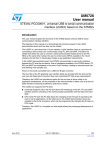
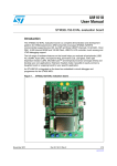
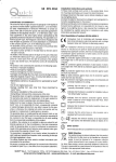
A parking ticket vending machine is a hand-held, battery operated device, inside of which a
thermal printer is interfaced with the STM32 microcontroller from STMicroelectronics. This
document focuses on the STEVAL-IPC002V1 demonstration board, whose objective is to
print and generate parking tickets for different types of vehicles. The application can easily
be modified to suit other applications where paper printing is to be managed directly by the
microcontroller, such as POS-based applications, railway and bus ticket printing
applications, standalone printers, and the like.
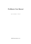
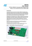
Figure 1.
STM32-based parking ticket vending machine
The thermal printer has an in-built stepper motor for thermal paper feeding, paper
movement, and so on. The stepper motor is controlled by a dedicated stepper-motor driver
with an SPI interface. The system operates on two Li-Ion batteries and an optional DC
adaptor. On-board battery chargers are available to charge the batteries from the DC
adaptor. The data to be printed is entered by way of touch keys, and can be verified on an
alphanumeric LCD.
June 2010
Doc ID 16916 Rev 1
1/30
www.st.com
Contents
UM0886
Contents
1
Definitions . . . . . . . . . . . . . . . . . . . . . . . . . . . . . . . . . . . . . . . . . . . . . . . . . 4
2
Features . . . . . . . . . . . . . . . . . . . . . . . . . . . . . . . . . . . . . . . . . . . . . . . . . . . 5
3
Getting started . . . . . . . . . . . . . . . . . . . . . . . . . . . . . . . . . . . . . . . . . . . . . . 6
4
3.1
Package . . . . . . . . . . . . . . . . . . . . . . . . . . . . . . . . . . . . . . . . . . . . . . . . . . . 6
3.2
Hardware installation . . . . . . . . . . . . . . . . . . . . . . . . . . . . . . . . . . . . . . . . . 6
3.3
Hardware layout . . . . . . . . . . . . . . . . . . . . . . . . . . . . . . . . . . . . . . . . . . . . . 9
System overview . . . . . . . . . . . . . . . . . . . . . . . . . . . . . . . . . . . . . . . . . . . 12
4.1
Hardware design . . . . . . . . . . . . . . . . . . . . . . . . . . . . . . . . . . . . . . . . . . . 12
4.1.1
Microcontroller(STM32) . . . . . . . . . . . . . . . . . . . . . . . . . . . . . . . . . . . . . 12
4.1.2
Battery connector . . . . . . . . . . . . . . . . . . . . . . . . . . . . . . . . . . . . . . . . . . 12
4.1.3
Thermal printer (FM205-HS) . . . . . . . . . . . . . . . . . . . . . . . . . . . . . . . . . 12
4.1.4
Alphanumeric LCD . . . . . . . . . . . . . . . . . . . . . . . . . . . . . . . . . . . . . . . . . 13
4.1.5
EEPROM . . . . . . . . . . . . . . . . . . . . . . . . . . . . . . . . . . . . . . . . . . . . . . . . 13
4.1.6
S-Touch-based keypad . . . . . . . . . . . . . . . . . . . . . . . . . . . . . . . . . . . . . 14
4.1.7
Power supply unit . . . . . . . . . . . . . . . . . . . . . . . . . . . . . . . . . . . . . . . . . . 14
4.2
Flowchart . . . . . . . . . . . . . . . . . . . . . . . . . . . . . . . . . . . . . . . . . . . . . . . . . 15
4.3
Hardware schematics . . . . . . . . . . . . . . . . . . . . . . . . . . . . . . . . . . . . . . . . 17
5
Bill of materials . . . . . . . . . . . . . . . . . . . . . . . . . . . . . . . . . . . . . . . . . . . . 21
6
Revision history . . . . . . . . . . . . . . . . . . . . . . . . . . . . . . . . . . . . . . . . . . . 29
2/30
Doc ID 16916 Rev 1
UM0886
List of figures
List of figures
Figure 1.
Figure 2.
Figure 3.
Figure 4.
Figure 5.
Figure 6.
Figure 7.
Figure 8.
Figure 9.
Figure 10.
Figure 11.
Figure 12.
Figure 13.
Figure 14.
Figure 15.
Figure 16.
Figure 17.
Figure 18.
Figure 19.
STM32-based parking ticket vending machine . . . . . . . . . . . . . . . . . . . . . . . . . . . . . . . . . . . 1
STM32-based parking ticket vending machine demonstration board . . . . . . . . . . . . . . . . . . 7
S-Touch-based keypad. . . . . . . . . . . . . . . . . . . . . . . . . . . . . . . . . . . . . . . . . . . . . . . . . . . . . 8
Sample printed ticket . . . . . . . . . . . . . . . . . . . . . . . . . . . . . . . . . . . . . . . . . . . . . . . . . . . . . . 8
Hardware layout: main board - top side . . . . . . . . . . . . . . . . . . . . . . . . . . . . . . . . . . . . . . . . 9
Hardware layout: main board - bottom side . . . . . . . . . . . . . . . . . . . . . . . . . . . . . . . . . . . . 10
Hardware layout: daughterboard S-Touch keypad - top side . . . . . . . . . . . . . . . . . . . . . . . 10
Hardware layout: daughterboard S-Touch keypad - bottom side . . . . . . . . . . . . . . . . . . . . 11
Block diagram of an STM32-based parking ticket vending machine . . . . . . . . . . . . . . . . . 12
Truth table for excitation sequence. . . . . . . . . . . . . . . . . . . . . . . . . . . . . . . . . . . . . . . . . . . 13
Timing diagram for excitation sequence . . . . . . . . . . . . . . . . . . . . . . . . . . . . . . . . . . . . . . . 13
Power block of STM32-based parking ticket vending machine . . . . . . . . . . . . . . . . . . . . . 14
Voltage regulators used in power block . . . . . . . . . . . . . . . . . . . . . . . . . . . . . . . . . . . . . . . 14
Flowchart . . . . . . . . . . . . . . . . . . . . . . . . . . . . . . . . . . . . . . . . . . . . . . . . . . . . . . . . . . . . . . 15
Schematic: microcontroller section . . . . . . . . . . . . . . . . . . . . . . . . . . . . . . . . . . . . . . . . . . . 17
Schematic: motor driver . . . . . . . . . . . . . . . . . . . . . . . . . . . . . . . . . . . . . . . . . . . . . . . . . . . 18
Schematic: connectors (printer, LCD and JTAG) . . . . . . . . . . . . . . . . . . . . . . . . . . . . . . . . 18
Schematic: power management section . . . . . . . . . . . . . . . . . . . . . . . . . . . . . . . . . . . . . . . 19
Schematic: S-Touch keypad . . . . . . . . . . . . . . . . . . . . . . . . . . . . . . . . . . . . . . . . . . . . . . . . 20
Doc ID 16916 Rev 1
3/30
Definitions
1
UM0886
Definitions
Table 1.
4/30
Definitions
Acronym
Definition
ESD
Electrostatic discharge
I2C
Inter-integrated circuit
JTAG
Joint test action group
LCD
Liquid crystal display
MCU
Microcontroller unit
POS
Point of sale
PTVM
Parking ticket vending machine
RTC
Real time clock
SPI
Serial peripheral interface
Doc ID 16916 Rev 1
UM0886
2
Features
Features
The STM32-based demonstration board has the following key features.
●
Thermal printer interfaced through SPI2.
●
Stepper motor driver interfaced through SPI1 used to rotate the printer head while
printing.
●
S-Touch™-based keypad for user interfacing. The S-Touch™ controller device is
interfaced through the I2C2. The keypad is used to enter the vehicle number and other
parameters, and set the date and time.
●
LED indication for battery status.
●
On-board JTAG connector for firmware upgrades and changes.
●
Alphanumeric LCD for displaying numbers and settings entered through the S-Touch™
keypad.
●
SPDT switch for switching the system ON and OFF.
●
Push button switch for resetting the system.
●
Rechargeable battery circuit.
●
On-board power supply. The entire system can be powered by either a DC adaptor
(9 V, 2.5 A) or battery (2 batteries of 3.7 V each, 1.8 Ah ratings).
●
Thermistor to monitor the temperature of the thermal head.
●
STM32 in-built RTC (real time clock) that provides date and time of printing.
●
EEPROM interfaced through I2C1. The last 20 vehicle numbers are stored in the
EEPROM.
Doc ID 16916 Rev 1
5/30
Getting started
UM0886
3
Getting started
3.1
Package
The STM32-based parking ticket vending machine demonstration board includes the
following items.
●
Hardware:
–
●
●
3.2
demonstration board
Documentation:
–
this user manual
–
schematics, gerber files, BOM
Firmware:
–
pre-programmed STM32 device soldered on the demonstration board
–
object files for the firmware
Hardware installation
The following instructions are for setting-up the STM32-based parking ticket vending
machine demonstration board.
Note:
1.
Connect the 9 V, 2.5 A DC adaptor or connect two Li-Ion batteries (3.7 V, 1800 mAH) to
the connectors B1+, B1-, B2+ and B2-.
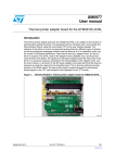
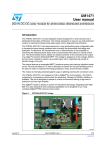
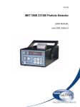
2.
Feed the thermal paper (50 to 52 mm width) with the glossy (thermal printing) side up
as shown in Figure 2.
Avoid running the demonstration board without inserting the thermal paper since this can
cause the printer to overheat and cause permanent damage.
3.
Switch on the board (SPDT ON/OFF power switch).
You should now see the word "VEHICLE" on the LCD.
4.
Select the vehicle type by pressing one of the following key combinations.
–
4 WHL: FUNC + 1
–
2 WHL: FUNC + 2
–
HEAVY FUNC + 3
For example, to select a 4 WHL type vehicle, press "FUNC" (function key) and then "1".
The selected vehicle type is displayed on the LCD for 1 second.
5.
The word "ENTRY" appears on the LCD. Press one of the following key combinations
to select the entry type.
–
SINGLE: FUNC + 7
–
PASS: FUNC + 8
The selected entry type is displayed on the LCD for 1 second.
6.
Enter the vehicle number (last 4 digits) by pressing the corresponding numeric keys on
the keypad.
The number is now displayed on the LCD.
7.
Send the print command by pressing the PRINT function (FUNC + 0).
The ticket is printed.
6/30
Doc ID 16916 Rev 1
UM0886
Getting started
The time can be set by pressing the SET function (FUNC + 9).
The 9 V adaptor is used to charge the batteries through the on-board battery charger.
To see the last 20 entries, press "FUNC" and then "6".
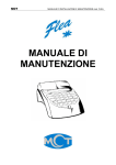
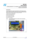
Figure 2.
STM32-based parking ticket vending machine demonstration board
4HERMALPAPER
4HERMALPRINTER
!LPHANUMERIC,#$
3TEPPERMOTORDRIVER
34-
*4!'CONNECTOR
0OWERONOFF30$4
34OUCHKEYBOARD
0OWER*ACK
"ATTERYCONNECTORS
2ELAY
!-V
8.
To replace the thermal paper, pull the black roll out of the printer. Place the paper (50 to
52 mm width) so that the glossy side faces up as shown in Figure 2. Put the black roll
back into place. If the paper is not inserted correctly the printout may not come out
properly.
Doc ID 16916 Rev 1
7/30
Getting started
UM0886
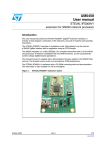
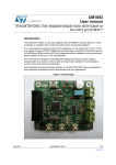
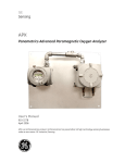
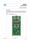
Figure 3.
S-Touch-based keypad
%3#ESCAPEKEY
&5.##,2
7(,&5.#
7(,&5.#
(%!69&5.#
#,2CLEARKEY
-%-/29&5.#
&5.#FUNCTIONKEY
0!33&5.#
3%4&5.#
3).',%&5.#
02).4&5.#
!-V
The vehicles are categorized as follows:
●
4 WHL = 4-wheelers (cars)
●
2 WHL = 2-wheelers (bikes and scooters)
●
HEAVY = heavy vehicles such as trucks or buses
The entry types are:
●
Single = single entry/exit
●
PASS = the user has a pass for multiple entries and exits.
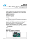
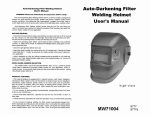
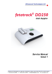
Figure 4 shows a sample printed ticket generated from the PTVM.
Figure 4.
8/30
Sample printed ticket
Doc ID 16916 Rev 1
UM0886
3.3
Getting started
Hardware layout
The STM32-based parking ticket vending machine demonstration board is built using
STMicroelectronics' ARM® Cortex-M3 core-based STM32F103RBT6 in a 64-pin LQFP64
package. The components used on this board are listed below. Figure 5 and Figure 6
provide the component layouts to assist you in locating the different component sections on
the board.
●
●
ST components:
–
STM32F103RBT6 (32-bit MCU)
–
L9935 (stepper motor driver)
–
STMPE1208S (S-Touch keypad)
–
M24C01-W (EEPROM)
–
L6924D (battery charger)
–
L5987A (step-down voltage regulator)
–
STM1061N31WX6F (low-power voltage detector for battery monitoring)
Non-ST components:
–
FM205-HS (thermal printer)
–
16X2 alphanumeric LCD
Refer to the bill of materials in Chapter 5 for a detailed list of components.
Figure 5.
Hardware layout: main board - top side
Doc ID 16916 Rev 1
9/30
Getting started
10/30
UM0886
Figure 6.
Hardware layout: main board - bottom side
Figure 7.
Hardware layout: daughterboard S-Touch keypad - top side
Doc ID 16916 Rev 1
UM0886
Getting started
Figure 8.
Hardware layout: daughterboard S-Touch keypad - bottom side
Doc ID 16916 Rev 1
11/30
System overview
UM0886
4
System overview
4.1
Hardware design
Figure 9.
Block diagram of an STM32-based parking ticket vending machine
As shown in Figure 9, the principal system controller is the STM32 microcontroller.
Figure 12 and Figure 13 show the power management blocks in more detail.
4.1.1
Microcontroller(STM32)
The STM32 is a 32-bit MCU based on the popular ARM 32-bit Cortex™-M3 CPU running at
72 MHz with a performance of 90 DMIPS with 1.25 DMIPS/MHz. The microcontroller
incorporates single-cycle multiplication and hardware division functions. It has 80 fast
general-purpose IOs to enhance the overall performance. The IOs are 5-volt tolerant.
The microcontroller has several communication interfaces, including multiple I2Cs, USARTs
(4.5 Mbps) and SPIs, a CAN 2.0B active interface and a USB 2.0 interface. For more
information, go to http://www.st.com.
The microcontroller works on a single voltage ranging from 2 to 3.6 V, unlike some other
microcontrollers that require a dual voltage. In this application the system operates at 3.3 V.
4.1.2
Battery connector
B1+ and B1-, B2+ and B2- are the four pins of the battery connector. Two Li-Ion batteries of
3.7 V and 1800 mAh each are to be connected with correct polarity.
4.1.3
Thermal printer (FM205-HS)
The thermal printer is a compact, high-speed thermal line dot printing mechanism. It can be
used with a measuring instrument and analyzer, a POS, a communication device or a data
terminal device.
12/30
Doc ID 16916 Rev 1
UM0886
System overview
The paper is fed in a forward direction when the motor shaft is rotating in the normal
direction (clockwise) as seen from the motor gear side. The motor is driven by a 2-2 phase
excitation, constant-current chopper method and feeds 0.125 mm of paper (equivalent to a
single dot pitch) every two steps of the motor drive signal. It is not possible to print while the
motor is rotating in the reverse direction.
Excitation sequence
As shown in Figure 10, the printer feeds the paper in the normal direction when the motor is
excited in the order of step 1, step 2, step 3, step 4, step 1, step 2... On the other hand, to
rotate the motor in the reverse direction, the motor must be driven in the reverse order: step
4, step 3, step 2, step 1, step 4, step 3, etc.
Figure 10. Truth table for excitation sequence
Figure 11. Timing diagram for excitation sequence
4.1.4
Alphanumeric LCD
A 16 by 2 cm alphanumeric LCD displays the entries entered through the keypad.
4.1.5
EEPROM
The EEPROM maintains records and stores the last 20 entries.
Doc ID 16916 Rev 1
13/30
System overview
4.1.6
UM0886
S-Touch-based keypad
The demonstration board incorporates an S-Touch keypad based on the STMPE1208SQTR
to navigate through the menus. This keypad is a 12-key daughterboard. Figure 3 shows the
placement of the keys.
4.1.7
Power supply unit
The power block is the main module of any hand-held system. This application requires
several voltages (3.3 V, 5 V, 6.5 V) to drive the various board components. The board can be
used in standalone/hand-held mode with two batteries. The circuit is implemented so that
the batteries are charged individually and in parallel by dedicated battery chargers, and
while discharging (application running on the batteries) they are connected in series. This
switching is done through a relay.
If the DC adaptor is plugged in, the voltage from the voltage regulator output excites the
relay, which changes the series connection of the batteries to a parallel connection and all
the power is taken from the adaptor.
Figure 12. Power block of STM32-based parking ticket vending machine
Figure 13. Voltage regulators used in power block
14/30
Doc ID 16916 Rev 1
UM0886
4.2
System overview
Flowchart
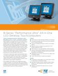
Figure 14 is a flowchart of the entire system.
Figure 14. Flowchart
67$57
,1,7,$/,=$7,21
57&&RQILJXUDWLRQ
*3,2¶V&RQILJXUDWLRQ
/&'&RQILJXUDWLRQ
67RXFK6HWWLQJV
$
67RXFK
5HVHWDQG5H
LQLWLDOL]H
,17(55837
&RQILJXUHH[WHUQDOOLQHLQWHUUXSWV
7RXFK(QGRISDSHU/RZEDWWHU\
<HV
,V3ULQW
)ODJ
6(7"
6WDUW3ULQWLQJ
12
$
<HV
6HW'DWH
,V6HW
'DWH
)ODJ
6(7"
12
%
<HV
,V(QWU\
)ODJ
6(7"
6HW(QWU\W\SH
12
<HV
6HW9HKLFOH 7\SH
,V
9HKLFOH
)ODJ
6(7"
12
<HV
6HW9HKLFOH
1XPEHU
,V
1XPEHU
)ODJ
6(7"
12
$
!-V
Doc ID 16916 Rev 1
15/30
System overview
UM0886
●
Start printing: the thermal printer starts printing stored data.
●
Set Date: modify the date and time of the system.
●
Set Entry Type: entry type 'Pass' or 'Single' is stored in the user buffer data.
●
Set Vehicle Type: the vehicle type is 2 WHL, 4 WHL or Heavy, and is stored in the user
buffer data.
●
Set Vehicle Number: the system stores the last 4 digits of the vehicle number entered
by the user.
Once all initializations are complete, various flag statuses are continuously checked within
the main state machine. When a key is pressed on the keypad, an interrupt is generated and
corresponding actions are taken by the firmware.
16/30
Doc ID 16916 Rev 1
Doc ID 16916 Rev 1
S)
&
&
X)
/
X+
<
.K]
5
0
26&B287
&
S)
26&B,1
<
0+]
&
S)
5
&
Q)
%7
5
3&B26&B,1
5
%$77(5<
3&B26&B287
9
9
'10
S)
&
%227B
%227B
5
N
5
86$57B5;
9%$7
3&B$ 17,B7$03
3&B26 &B,1
3&B26 &B2 87
3'B26&B,1
3'B26&B287
Q567
3&
3&
3&
3&
966$
9''$
3$B :.83
3$ 3$ N
670)5%7
8
3&B26&B,1
3&B26&B287
26&B,1
26&B287
Q567
0&B:&B3&
5(6(7B1 /&'B56B3&
670B287B3&
/&'B'B3$
/&'B'B3$
86$57B7;
9%$7
9
/&'B'B3%
/&'B'B3%
%227B
0&B,&B6'$
0&B,&B6&/
/&'B'B3%
-7$*B3%
-7$*B6:'B3%
/&'B'B3'
/&'B'B3&
/&'B'B3&
/&'B(B3&
-7$*B6:'B3$
-7$*B6:'B3$
9''B
966B
3%
3%
%227
3%
3%
3%
3%
3%
3'
3&
3&
3&
3$
3$
3$
966B
9''B
3$
3$
3$
3$
3&
3&
3%
3%
3%
3%
3%
966B
9''B
5
N
5
N
9
9''B
966B
3$ 3$ 3$ 3$ 3$ 3$ 3&
3&
3&
3&
3%
3%
3%
3%
60'B63,B0,62
9
60'B&61B3$
60'B63,B6&. 60'B63,B026,
60'B(1B3& )06B70B$1B3&
/&'B6:,7&+B3%
676B7,17B3%
%227B
676B,&B6&/ 676B,&B6'$
&
&
Q)
&
676B,&B6&/
5
N
Q)
&
9
5
N
Q) Q)
&
9
5('/('
'
676B,&B6'$
Q) Q)
&
5
0,&52&21752//(5
6:
9
&21
-7$*B6:'B3$
306B*B3$
)06B3(0B3$
)06B/$7B3$
)06B67%B3$
)06B67%B3$
)06B67%B3&
)06B67%B3&
)06B67%B3&
)06B67%B3&
)06B63,B026,
)06B63,B0,62
)06B63,B&/.
5
N
9
-
4.3
Q567
86$57B7;
86$57B5;
UM0886
System overview
Hardware schematics
The following figures represent the schematic diagrams for the board.
Figure 15. Schematic: microcontroller section
!-V
17/30
System overview
UM0886
Figure 16. Schematic: motor driver
8
60'B)06B3+
60'B63,B6&.
60'B63,B026,
60'B63,B0,62
9
&
Q)
60'B&61B3$
60'B(1B3&
60'B)06B3+
*1'
*1'
287$ 65$
6&. 287$
1&
6',
6'2
96
9&&
26&
&61
&'59
(1
287%
287% 65%
*1'
*1'
02725'5,9(5
60'B)06B3+
9
60'B)06B3+
Q)
&
Q)
&
Q)
5
5
/
&$3
&
&
!-V
Figure 17. Schematic: connectors (printer, LCD and JTAG)
5
9
&211
.
5
9
)06B3(0B3$
306B)06B9+
& )06B63,B026,
X) )06B63,B&/.
5
N
)06B67%B3&
)06B67%B3&
)06B67%B3&
9
)06B70B$1B3&
9
)06B67%B3&
)06B67%B3$
)06B67%B3$
)06B/$7B3$
)06B63,B0,62
306B)06B9+
60'B)06B3+
60'B)06B3+
60'B)06B3+
60'B)06B3+
35,17(5&211(&725
5
N
&211/&'
3&$
3&2
3(0
1&
1&
9+
9+
',1
&/.
*1'
*1'
67%
67%
67%
9''
70
70
67%
67%
67%
*1'
*1'
/$7
'2
9+
9+
3+
3+
3+
3+
966
9''
&2175$67
56
5:5
(1
'
'
'
'
'
'
'
'
/('
/('
/&'B56B3&
/&'B(B3&
/&'B'B3&
/&'B'B3&
/&'B'B3'
/&'B'B3%
/&'B'B3$
/&'B'B3$
/&'B'B3%
/&'B'B3%
5
/('
4
9
5
N
/&'B6:,7&+B3%
5
/('
6773)9B3
9
/&'&211(&725
5
)06+6
5
N
5
N
N
5
N
-7$*B&211
5
-
-7$*B3%
5
N
-7$*B6:'B3$
-7$*B6:'B3$
-7$*B6:'B3$
57&.
5
12786('
-7$*B6:'B3%
Q567
5
N
'%*54
'%*$&.
5
N
9
9
N 5
-7$*B&211
!-V
18/30
Doc ID 16916 Rev 1
Doc ID 16916 Rev 1
5
0
'&B$'
5
.
N
5
&
X)
6736/8
'
6763)/B3
4
6773)9B3
4
287
287
*1'
9
,1
&
Q)
9%$7B287
5
5
N
'&B$'
306B*B3$
-
8
/'B '3$.
9%$7B287
'
6736/8
&
X)9
%
%
5(/$<63'7
306B)06B9+
'
',2'(
9%$7B'&B$'
%
/6
6:63'7
6:
%
%
&21
&21
-
-
5
5
.
/' '75
1&
9287
9287
1&
5(*B287
*1'
9287
9287
9,1
%
%
&
X)9
9
&
Q)
9%$7B'&B$'
8
&
X)
9%$7B'&B$'
'
6736/
X+$
/
Y
5
N
5
N
&
Q)
287
6<1&+
,1+
&203
8
5
N
5
N
&
X)
&
X)9
9
9
9%$7B'&B$'
287
287
*1'
670B287B3&
9&&
*1'
)6:
)%
,1
8
/'B '3$.
/$
&
Q)
8
6701
& 3)
5
N
9%$7B'&B$'
9&&
966
287
&
Q)
Figure 18.
32:(56833/<6(&7,21
UM0886
System overview
Schematic: power management section
!-V
19/30
3$'
&21
&
S)
3$'
&21
&
S)
676B,&B6'$ 676B,&B6&/ 676B7,17B3% Y
*3,2B
*3,2B
6'$7$
6&/.
7B,17
*B,17
%((3
7&/.
*3,2B
*3,2B
8
&
S)
5
N
6703(6
&
S)
6
6
6
6B,1B
6B,1B
6B,1B
9
95(*
9
*1'
6B,1B
6B,1B
6B,1B
&
S)
3$'
&21
Y
&
&
Q)
6
6
6
&
S)
6
6
6
X)9
3$'
&21
3$'
&21
&
S)
3$'
&21
&
S)
728&+.(<6
3$'
&21
Y
6703(66(&7,21
3$'
&21
&
S)
5(6(7B1
6
6
6
*3,2B
*3,2B
*3,2B
*3,2B
,'B
,'B
5(6(7B1
6B,1B
6B,1B
6B,1B
*3,2B
*3,2B
*3,2B
*3,2B
9
*1'
6B5()
6B,1B
6B,1B
6B,1B
Doc ID 16916 Rev 1
20/30
6
6
6
6
6
6
6
6
6
&
S)
3$'
&21
6
&
S)
3$'
&21
Y
&21
-
'%B&211
&
S)
676B,&B6'$ 676B,&B6&/ 676B7,17B3% 5(6(7B1
3$'
&21
6
6
3$'
&21
&
S)
&21
-
System overview
UM0886
Figure 19. Schematic: S-Touch keypad
!-V
Bill of materials
Table 2.
STEVAL-IPC002V1 BOM
Category
Doc ID 16916 Rev 1
ST devices
Serial
Ref.
no.
description
UM0886
5
Component description
Package
Manufacturer
Manufacturer’s
ordering
code/orderable part
number or
equivalent
U1
Microcontroller, ARM 32-bit
Cortex™-M3 CPU, 128 kΩ
Flash, 64 kΩ RAM
LQFP64
STMicroelectronics
STM32F103RBT6
2
U2
Two-phase stepper-motor
driver
PowerSO-20
STMicroelectronics
L9935
3
U4
Xpander logic™ with
12-channel touchkey
(S-Touch)
QFN40
STMicroelectronics
STMPE1208S
4
U6,U7
Battery charger system
VFQFPN16
STMicroelectronics
L6924D
5
U8
Voltage regulator
SO-8
STMicroelectronics
LD1117D33TR
6
U13
3 A step-down switching
regulator
HSOP-8
STMicroelectronics
L5987A
7
U20
1 Kbit serial I²C bus
EEPROM
SO8
STMicroelectronics
M24C01-WMN6TP
8
U21
Low-power voltage detector,
3.1 V threshold typical
SOT23-3 (WX) STMicroelectronics
STM1061N31WX6F
9
U22,U23
Low-drop fixed and
adjustable positive voltage
regulators
DPAK
STMicroelectronics
LD1117DT50TR
Q1
P-Channel 20 V - 0.065 W 5 A SOT23-6L
2.5 V-drive STripFET™ II
power MOSFET
SOT23-6L
STMicroelectronics
STT5PF20V
10
Supplier
ordering code
21/30
Bill of materials
1
Supplier
Category
STEVAL-IPC002V1 BOM (continued)
Serial
Ref.
no.
description
Component description
Package
Manufacturer
Manufacturer’s
ordering
code/orderable part
number or
equivalent
SO8
STMicroelectronics
STS7PF30L
Supplier
ordering code
11
Q3
P-Channel 30 V, 0.16 Ω, 7 A,
SO8
STripFET™ II power
MOSFET
12
D1, D7, D8
Power Schottky rectifier
SMA
STMicroelectronics
STPS3L60U
1
Y1
Quartz crystal 8 MHz
11.35 x 4.35
mm, SS4
Jauch
Q 8.0-SS4-22-30/30
2
Y2
32 kHz
Jauch
Q 0.032768MMTF32-12.5-30
1
SW5
SPDT slide switch
3-pin through
hole
APEM
APEM
25136NAH6
Farnell
1082285
2
SW3
Push button switch
(6 x 6 mm)
push button,
through hole
Tyco Electronics
FSM2JH
Farnell
Part# 1555981
Protectron
P9603-20-15-1
ST devices
Crystal and
Oscillator
Doc ID 16916 Rev 1
Connectors,
jumpers and
switches
Supplier
J1
JTAG connector
4
CONN1
30-pin SMD connector
SMD
SAMTEC
ZF1-30-01-T-WT
5
J8, J2, J9
Header, pin, 2.54 mm,
straight 2-WAY, single row,
gold Flash
Single row
straight,
through hole,
2-pin
Protectron
P9101-02-12-1
6
J7
Socket, DC power JACK,
2.5 mm, right angle, locking
type
Through hole
Protectron
PDCJ01-08
SAMTEC ZF1-30-01-T-WT
UM0886
3
Box header,
straight
20-way, 2 x 10
pin, 2.54 x 2.54
mm pitch
Bill of materials
22/30
Table 2.
Category
Connectors,
jumpers and
switches
Doc ID 16916 Rev 1
LEDs
STEVAL-IPC002V1 BOM (continued)
Serial
Ref.
no.
description
Component description
Package
Manufacturer
Manufacturer’s
ordering
code/orderable part
number or
equivalent
Single row
straight,
Through hole,
16pin
Protectron
P9101-16-12-1
Supplier
Supplier
ordering code
Mouser
614-HU2032-LF
7
LCD CONN
Header, pin, 2.54 mm,
straight 16-WAY, single row,
Gold Flash
8
BT1
Battery CR2032 holder
Through hole
Renata
HU2032-LF
9
J3,J4
HEADER, PIN, 2.54 mm,
straight 6-WAY, single row,
Gold Flash
Single row
straight,
through hole,
2pin
Protectron
P9101-06-12-1
1
D6
Yellow LED
SMD1206
OSRAM
LYN971-Z
Farnell
Part# 1226417
2
D9
Green LED
SMD1206
OSRAM
LGN971
Farnell
Part# 1226371
3
D10
Red LED
SMD1206
DIALIGHT
Corporation
5988210107F
Farnell
Part# 1465997
UM0886
Table 2.
Bill of materials
23/30
Category
Doc ID 16916 Rev 1
Capacitors
STEVAL-IPC002V1 BOM (continued)
Serial
Ref.
no.
description
Component description
Package
Manufacturer
1
C28
5 pF
SMD0805
Any
2
C31,C36
10 pF
SMD0805
Any
3
C32,C39
20 pF
SMD0805
Any
4
C34
82 pF
SMD0805
5
C24,C49,
C51
1 nF
SMD0805
6
C48,C50
22 nF
SMD0805
7
C33
47 nF
SMD0805
8
C14,C15,
C16,C17,
C18,C19,
C20,C21,
C22,C27,
C35,C44,
C47,C53,
C56
100 nF
SMD0805
Manufacturer’s
ordering
code/orderable part
number or
equivalent
Supplier
Supplier
ordering code
Bill of materials
24/30
Table 2.
Any
Any
UM0886
Category
STEVAL-IPC002V1 BOM (continued)
Serial
Ref.
no.
description
Component description
Package
Manufacturer
Any
Doc ID 16916 Rev 1
9
C30
220 nF
SMD0805
10
C40,C41
1 µF/16 V
SMD1206
11
C38,C43
4.7 µF/16 V
EIA 3528-21/
size A
12
C23
10 µF
EIA 3528-21/
size A
Any
13
C13,C45,
C46,C52
10 µF
EIA 3528-21/
size A
Any
14
C29
22 µF/25 V
EIA 3528-21/
size B
Any
15
C25, C42
47 µF/16 V
EIA 3528-21/
size C
Any
16
C37
Aluminum electrolytic
capacitors - SMD 330 µF/
10 V
SMD
Electrolytic,
6.3 mm
diameter x 11
mm L
Nichicon
1
L1
10 µH
SMD
Any
2
L2
10 µH/2.5 A
SMD
Bourns
1
R1
DNM
SMD0805
Any
2
R2,R13,R29
,R39,R47
0
SMD0805
Any
3
R3
180 Ω
SMD0805
Any
4
R4
27 kΩ
SMD0805
Any
Capacitors
Manufacturer’s
ordering
code/orderable part
number or
equivalent
Supplier
2
UCD1A331MNL1GS
Mouser
647UCD1A331MNL
1GS
SDR1005-100ML
Mouser
652-SDR1005100ML
Inductors
25/30
Bill of materials
Resistors
Supplier
ordering code
UM0886
Table 2.
Category
Doc ID 16916 Rev 1
Resistors
STEVAL-IPC002V1 BOM (continued)
Serial
Ref.
no.
description
Package
Manufacturer
6
R6,R10,
R12,R14,
R15,R16,
R17,R18,
R19,R20,
R21,R22,
R32,R44,
R45,R55
10 kΩ
SMD0805
Any
7
R7,R8
0.4 Ω
SMD0805
Any
8
R9
100 Ω
SMD0805
Any
9
R11,R50,R6
0
500 Ω
SMD0805
Any
10
R25,R26
100 kΩ
SMD0805
Any
11
R27,R56
1 MΩ
SMD0805
Any
12
R28
DNM
SMD0805
Any
13
R30,R31,
R36,R37
4.7 kΩ
SMD0805
Any
14
R33
150 Ω
SMD0805
Any
15
R34
70 kΩ
SMD0805
Any
16
R35
1.5 kΩ
SMD0805
Any
17
R40
330 Ω
SMD0805
Any
18
R41,R48,
R49,R54
1 kΩ
SMD0805
Any
19
R42
2 kΩ
SMD0805
Any
20
R43,R46
470 Ω
SMD0805
Any
21
R51,R57
13.5 kΩ
SMD0805
Any
Supplier
Supplier
ordering code
UM0886
Component description
Manufacturer’s
ordering
code/orderable part
number or
equivalent
Bill of materials
26/30
Table 2.
Category
STEVAL-IPC002V1 BOM (continued)
Serial
Ref.
no.
description
Doc ID 16916 Rev 1
Note:
Package
Manufacturer
22
R5,
R52,R58
3.5 kΩ
SMD0805
Any
23
R53,R59
12 kΩ
SMD0805
Any
1
Thermal
printer
Thermal printer
Modular
APS
2
U3
Oriole LCD, 16 x 2
alpha-numeric LCD
Modular
Oriole
3
Relay
Relay, SPDT
5-pin through
hole
Tyco electronics
Resistors
Misc
Component description
Manufacturer’s
ordering
code/orderable part
number or
equivalent
Supplier
Supplier
ordering code
FM 205 – HS
Evolute
FM 205 – HS
PCH-105D2H,000
Digikey
PB890-ND
UM0886
Table 2.
Not mounted: R1, R28. An equivalent term has been used where the exact part number from the mentioned vendor may not have
been used.
Bill of materials
27/30
Category
ST devices
STEVAL-IPC002V1 touch daughterboard BOM list
Serial
Ref.
no. description
Component description
Package
Manufacturer
Manufacturer’s
ordering
code/orderable part
number or
equivalent
STMPE1208SQTR
Supplier
Supplier
ordering code
-
-
1
U1
S-Touch
QFN40
STMicroelectronics
1
C1,C2,C3,C
4,C5,C6,C7,
C8,C9,C10,
C11,C12
1 pF
SMD0805
Any
-
-
2
C15
5 pF
SMD0805
Any
-
-
3
C14
100 nF
SMD0805
Any
-
-
4
C13
10 µF 6.3 V
EIA 3528-21/
Size A
Any
-
-
Resistors
1
R1
10 kΩ
SMD0805
Any
-
-
Connectors
1
J1 and J2
6 pin socket, 2.5 mm pitch
Through hole
Any
-
-
Capacitors
Doc ID 16916 Rev 1
Note:
Bill of materials
28/30
Table 3.
As per the capacitor tuning of the STMPE1208SQTR, C3-C12 are not mounted. An equivalent term has been used where the
exact part number from the mentioned vendor may not have been used.
UM0886
UM0886
6
Revision history
Revision history
Table 4.
Document revision history
Date
Revision
17-Jun-2010
1
Changes
Initial release.
Doc ID 16916 Rev 1
29/30
UM0886
Please Read Carefully:
Information in this document is provided solely in connection with ST products. STMicroelectronics NV and its subsidiaries (“ST”) reserve the
right to make changes, corrections, modifications or improvements, to this document, and the products and services described herein at any
time, without notice.
All ST products are sold pursuant to ST’s terms and conditions of sale.
Purchasers are solely responsible for the choice, selection and use of the ST products and services described herein, and ST assumes no
liability whatsoever relating to the choice, selection or use of the ST products and services described herein.
No license, express or implied, by estoppel or otherwise, to any intellectual property rights is granted under this document. If any part of this
document refers to any third party products or services it shall not be deemed a license grant by ST for the use of such third party products
or services, or any intellectual property contained therein or considered as a warranty covering the use in any manner whatsoever of such
third party products or services or any intellectual property contained therein.
UNLESS OTHERWISE SET FORTH IN ST’S TERMS AND CONDITIONS OF SALE ST DISCLAIMS ANY EXPRESS OR IMPLIED
WARRANTY WITH RESPECT TO THE USE AND/OR SALE OF ST PRODUCTS INCLUDING WITHOUT LIMITATION IMPLIED
WARRANTIES OF MERCHANTABILITY, FITNESS FOR A PARTICULAR PURPOSE (AND THEIR EQUIVALENTS UNDER THE LAWS
OF ANY JURISDICTION), OR INFRINGEMENT OF ANY PATENT, COPYRIGHT OR OTHER INTELLECTUAL PROPERTY RIGHT.
UNLESS EXPRESSLY APPROVED IN WRITING BY AN AUTHORIZED ST REPRESENTATIVE, ST PRODUCTS ARE NOT
RECOMMENDED, AUTHORIZED OR WARRANTED FOR USE IN MILITARY, AIR CRAFT, SPACE, LIFE SAVING, OR LIFE SUSTAINING
APPLICATIONS, NOR IN PRODUCTS OR SYSTEMS WHERE FAILURE OR MALFUNCTION MAY RESULT IN PERSONAL INJURY,
DEATH, OR SEVERE PROPERTY OR ENVIRONMENTAL DAMAGE. ST PRODUCTS WHICH ARE NOT SPECIFIED AS "AUTOMOTIVE
GRADE" MAY ONLY BE USED IN AUTOMOTIVE APPLICATIONS AT USER’S OWN RISK.
Resale of ST products with provisions different from the statements and/or technical features set forth in this document shall immediately void
any warranty granted by ST for the ST product or service described herein and shall not create or extend in any manner whatsoever, any
liability of ST.
ST and the ST logo are trademarks or registered trademarks of ST in various countries.
Information in this document supersedes and replaces all information previously supplied.
The ST logo is a registered trademark of STMicroelectronics. All other names are the property of their respective owners.
© 2010 STMicroelectronics - All rights reserved
STMicroelectronics group of companies
Australia - Belgium - Brazil - Canada - China - Czech Republic - Finland - France - Germany - Hong Kong - India - Israel - Italy - Japan Malaysia - Malta - Morocco - Philippines - Singapore - Spain - Sweden - Switzerland - United Kingdom - United States of America
www.st.com
30/30
Doc ID 16916 Rev 1