1
UM0678
User manual
STEVAL-ISB008V1, USB Li-Ion battery charger and
gas gauge, based on the STw4102
Introduction
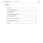
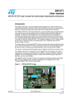
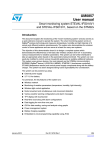
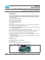
This user manual describes an easy, compact, and economical solution to charging Li-Ion
batteries using a USB port and a DC adaptor. In addition, battery capacity monitoring can
be done through the efficient built-in gas gauge system of the STw4102 device.The board
has the following devices:
■
STw4102 battery charging device
■
USBLC6-2 ESD protection device
■
STM32F103C6 microcontroller
■
LD2985BXX30 voltage regulator
Key features:
■
The STw4102 is used for charging a battery through a USB or the external DC adaptor
■
The STw4102 supports gas gauge applications
■
An onboard STM32 microcontroller is used for enumeration and controlling the STw4102
to comply with USB specifications
■
Charging and discharging status is indicated by dual-color LEDs
■
Gas gauge: battery capacity status shown in five levels using LEDs in steps of 20 % each
■
This can be used as a standalone Li-Ion battery charger in various applications
The Li-Ion battery charger device can be used in the following applications:
■
Standalone chargers: already implemented in the STEVAL-ISB008V1. An explanation is
given in this document
■
USB-powered chargers: already implemented in the STEVAL-ISB008V1. An explanation
is given in this document
■
PDAs
■
Handheld devices
■
Cellular phones (GSM, CDMA, WCDMA)
■
Cordless phones
■
Digital cameras, USB appliances, blue tooth devices, etc.
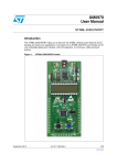
Figure 1.
STEVAL-ISB008V1, USB Li-Ion battery charger
!-V
July 2010
Doc ID 15407 Rev 1
1/28
www.st.com
Contents
UM0678
Contents
1
2
Getting started . . . . . . . . . . . . . . . . . . . . . . . . . . . . . . . . . . . . . . . . . . . . . . 5
1.1
Package . . . . . . . . . . . . . . . . . . . . . . . . . . . . . . . . . . . . . . . . . . . . . . . . . . . 5
1.2
Setting up the board . . . . . . . . . . . . . . . . . . . . . . . . . . . . . . . . . . . . . . . . . . 5
1.3
Hardware layout . . . . . . . . . . . . . . . . . . . . . . . . . . . . . . . . . . . . . . . . . . . . . 6
1.4
System architecture description . . . . . . . . . . . . . . . . . . . . . . . . . . . . . . . . . 6
System overview . . . . . . . . . . . . . . . . . . . . . . . . . . . . . . . . . . . . . . . . . . . . 7
2.1
3
4
General description of product architecture . . . . . . . . . . . . . . . . . . . . . . . . 7
Working of board . . . . . . . . . . . . . . . . . . . . . . . . . . . . . . . . . . . . . . . . . . . . 8
3.1
Operational description . . . . . . . . . . . . . . . . . . . . . . . . . . . . . . . . . . . . . . . 8
3.2
Initial settings for new battery . . . . . . . . . . . . . . . . . . . . . . . . . . . . . . . . . . . 9
3.3
Battery charging and discharging in the case of the STw4102 . . . . . . . . 10
Hardware design description . . . . . . . . . . . . . . . . . . . . . . . . . . . . . . . . . 13
4.1
Microcontroller (STM32) . . . . . . . . . . . . . . . . . . . . . . . . . . . . . . . . . . . . . . 13
4.2
Battery charger (STw4102) . . . . . . . . . . . . . . . . . . . . . . . . . . . . . . . . . . . 14
4.3
ESD protection device . . . . . . . . . . . . . . . . . . . . . . . . . . . . . . . . . . . . . . . 14
4.4
Voltage regulator . . . . . . . . . . . . . . . . . . . . . . . . . . . . . . . . . . . . . . . . . . . 14
4.5
Power MOSFET . . . . . . . . . . . . . . . . . . . . . . . . . . . . . . . . . . . . . . . . . . . . 15
5
Firmware architecture description . . . . . . . . . . . . . . . . . . . . . . . . . . . . 16
6
Connectors and jumpers . . . . . . . . . . . . . . . . . . . . . . . . . . . . . . . . . . . . 17
7
6.1
JTAG connector . . . . . . . . . . . . . . . . . . . . . . . . . . . . . . . . . . . . . . . . . . . . 17
6.2
USB connector . . . . . . . . . . . . . . . . . . . . . . . . . . . . . . . . . . . . . . . . . . . . . 18
6.3
Power supply connector . . . . . . . . . . . . . . . . . . . . . . . . . . . . . . . . . . . . . . 18
Hardware schematic . . . . . . . . . . . . . . . . . . . . . . . . . . . . . . . . . . . . . . . . 19
7.1
Bill of materials . . . . . . . . . . . . . . . . . . . . . . . . . . . . . . . . . . . . . . . . . . . . . 22
8
References . . . . . . . . . . . . . . . . . . . . . . . . . . . . . . . . . . . . . . . . . . . . . . . . 26
9
Revision history . . . . . . . . . . . . . . . . . . . . . . . . . . . . . . . . . . . . . . . . . . . 27
2/28
Doc ID 15407 Rev 1
UM0678
List of tables
List of tables
Table 1.
Table 2.
Table 3.
Table 4.
Table 5.
Table 6.
Table 7.
Table 8.
Table 9.
Table 10.
Table 11.
Table 12.
Table 13.
Table 14.
Table 15.
Description of firmware actions in USB charging mode . . . . . . . . . . . . . . . . . . . . . . . . . . . . 8
Different states of device shown through LED D2 status . . . . . . . . . . . . . . . . . . . . . . . . . . . 8
J7 jumper setting . . . . . . . . . . . . . . . . . . . . . . . . . . . . . . . . . . . . . . . . . . . . . . . . . . . . . . . . 10
J4 jumper setting . . . . . . . . . . . . . . . . . . . . . . . . . . . . . . . . . . . . . . . . . . . . . . . . . . . . . . . . 10
Battery capacity shown through level-LEDs D4 to D8 . . . . . . . . . . . . . . . . . . . . . . . . . . . . 11
J6 pin description . . . . . . . . . . . . . . . . . . . . . . . . . . . . . . . . . . . . . . . . . . . . . . . . . . . . . . . . 12
Microcontroller details . . . . . . . . . . . . . . . . . . . . . . . . . . . . . . . . . . . . . . . . . . . . . . . . . . . . . 13
STw4102 details . . . . . . . . . . . . . . . . . . . . . . . . . . . . . . . . . . . . . . . . . . . . . . . . . . . . . . . . . 14
USBLC6 details . . . . . . . . . . . . . . . . . . . . . . . . . . . . . . . . . . . . . . . . . . . . . . . . . . . . . . . . . 14
Voltage regulator . . . . . . . . . . . . . . . . . . . . . . . . . . . . . . . . . . . . . . . . . . . . . . . . . . . . . . . . 14
MOSFET . . . . . . . . . . . . . . . . . . . . . . . . . . . . . . . . . . . . . . . . . . . . . . . . . . . . . . . . . . . . . . . 15
JTAG pin description . . . . . . . . . . . . . . . . . . . . . . . . . . . . . . . . . . . . . . . . . . . . . . . . . . . . . 17
USB connector pin description . . . . . . . . . . . . . . . . . . . . . . . . . . . . . . . . . . . . . . . . . . . . . . 18
BOM . . . . . . . . . . . . . . . . . . . . . . . . . . . . . . . . . . . . . . . . . . . . . . . . . . . . . . . . . . . . . . . . . . 22
Document revision history . . . . . . . . . . . . . . . . . . . . . . . . . . . . . . . . . . . . . . . . . . . . . . . . . 27
Doc ID 15407 Rev 1
3/28
List of figures
UM0678
List of figures
Figure 1.
Figure 2.
Figure 3.
Figure 4.
Figure 5.
Figure 6.
Figure 7.
Figure 8.
Figure 9.
Figure 10.
Figure 11.
Figure 12.
Figure 13.
Figure 14.
Figure 15.
Figure 16.
4/28
STEVAL-ISB008V1, USB Li-Ion battery charger . . . . . . . . . . . . . . . . . . . . . . . . . . . . . . . . . 1
STEVAL-ISB008V1, USB Li-Ion battery charger parts . . . . . . . . . . . . . . . . . . . . . . . . . . . . . 5
Hardware layout details . . . . . . . . . . . . . . . . . . . . . . . . . . . . . . . . . . . . . . . . . . . . . . . . . . . . 6
System architecture details. . . . . . . . . . . . . . . . . . . . . . . . . . . . . . . . . . . . . . . . . . . . . . . . . . 7
Initial setting for new battery before power-on . . . . . . . . . . . . . . . . . . . . . . . . . . . . . . . . . . . 9
Setting of jumpers after power-on. . . . . . . . . . . . . . . . . . . . . . . . . . . . . . . . . . . . . . . . . . . . 10
Battery charging using the STw4102 . . . . . . . . . . . . . . . . . . . . . . . . . . . . . . . . . . . . . . . . . 11
Discharging the battery . . . . . . . . . . . . . . . . . . . . . . . . . . . . . . . . . . . . . . . . . . . . . . . . . . . . 12
System block diagram . . . . . . . . . . . . . . . . . . . . . . . . . . . . . . . . . . . . . . . . . . . . . . . . . . . . 13
Firmware flow chart . . . . . . . . . . . . . . . . . . . . . . . . . . . . . . . . . . . . . . . . . . . . . . . . . . . . . . 16
JTAG connector . . . . . . . . . . . . . . . . . . . . . . . . . . . . . . . . . . . . . . . . . . . . . . . . . . . . . . . . . 17
Mini-B USB connector . . . . . . . . . . . . . . . . . . . . . . . . . . . . . . . . . . . . . . . . . . . . . . . . . . . . 18
Power supply connector . . . . . . . . . . . . . . . . . . . . . . . . . . . . . . . . . . . . . . . . . . . . . . . . . . . 18
Microcontroller section schematic. . . . . . . . . . . . . . . . . . . . . . . . . . . . . . . . . . . . . . . . . . . . 19
STw4102 battery charger, MOSFET_STT5PF20V, wall adaptor and anti tamper circuit
schematics . . . . . . . . . . . . . . . . . . . . . . . . . . . . . . . . . . . . . . . . . . . . . . . . . . . . . . . . . . . . . 20
Boot jumpers, JTAG connector, power supply and USB schematics . . . . . . . . . . . . . . . . . 21
Doc ID 15407 Rev 1
UM0678
Getting started
1
Getting started
1.1
Package
The STEVAL-ISB008V1 demonstration board package includes the following items:
●
Hardware content:
–
●
●
1.2
Demonstration board STEVAL-ISB008V1
Documentation:
–
User manual
–
Schematics, Gerber files, BOM
Microcontroller firmware:
–
Pre-programmed STM32F103C6T6A device soldered onto the demonstration
board
–
Object files are also available for the firmware
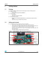
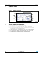
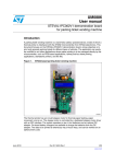
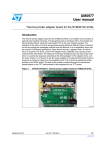
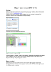
Setting up the board
●
The USB Li-Ion battery charger can be set up as follows:
–
Connect the Li-Ion battery pack to the board with appropriate polarity
–
Connect either the adapter or USB cable to the board. If both voltage sources are
connected, then the adapter considers as source for battery charging
–
Check the status of D2 LED. D2 is green during charging of the battery and is red
during discharging
–
Five LEDs show the available capacity of the battery.
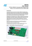
Figure 2.
STEVAL-ISB008V1, USB Li-Ion battery charger parts
*4!'CONNECTOR
3WITCH
"ATTERYCONNECTOR
53"MINI
CONNECTOR
347
,OADCONNECTOR
34-
"ATTERYCONNECTOR
6POWER
CONNECTOR
,%$INDICATORFOR
CHARGINGAND
DISCHARGING
#APACITYINDICATOR
!-V
Doc ID 15407 Rev 1
5/28
Getting started
1.3
UM0678
Hardware layout
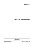
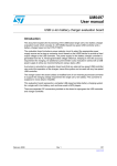
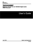
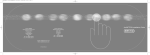
The hardware layout of the PCB is shown in Figure 3 which shows all the components
mounted on the board.
Figure 3.
Hardware layout details
-7$*
&RQQHFWRU
6ZLWFK
%DWWHU\
&RQQHFWRU
0LQL86%
&RQQHFWRU
67Z
670
/RDG
&RQQHFWRU
3RZHU
&RQQHFWRU
%DWWHU\
&RQQHFWRU
%DWWHU\
&RQQHFWRU
/('¶V
!-V
1.4
6/28
System architecture description
●
The application works as a Li-Ion battery charger
●
The system can be used both in USB mode and also adapter mode
●
The system consists of a battery charger section for a Li-Ion battery and a
microcontroller section for controlling actions
●
LEDs available on the board indicate the status of the charging conditions
●
Gas gauge/battery capacity status through Leds in steps of 20 % each
●
A JTAG connector is available to program the microcontroller.
Doc ID 15407 Rev 1
UM0678
System overview
2
System overview
2.1
General description of product architecture
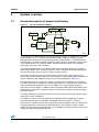
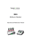
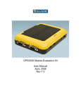
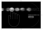
Figure 4.
System architecture details
7ALL!DAPTER
*4!'#ONNECTOR
3403,5
2EGULATOR
-AI
53"0WR
)3%
23%
"!44
6$
,%$S
53"
3$!
3$!
34-
)#)NTERFACE
4IMER/UT
"!44%29
)#'
3#,
3#,
)/
)/
347
-/3&%4
,O
AD
M
%/#('
072$%4%#4.
)#'
6OU
#+(Z
3ENSE
!-V
As described in the block diagram, the STw4102 battery charger, in addition to the STM32
microcontroller, acts as a completely standalone battery charger featuring gas gauge
implementation, which shows the remaining capacity of the battery in an efficient manner
with the help of five LEDs assigned to different capacity levels. The different capacity levels
are mentioned in the user interface section. Similarly, two status LEDs show charging,
discharging, and some faulty conditions.
The firmware programmed on the demonstration board considers the battery capacity as
1200 mAh by default. This “maximum capacity” value is used to find out the percentage of
the available battery capacity which is shown using the 5 LEDs.
The maximum capacity value can be changed by the user using the S1 switch and J7
jumper. This needs to be done when the user connects a battery to the demonstration board
which is different to the 1200 mAH rating. This is further explained in Section 3.2.
The STw4102 supports a 24-bit accumulator. The LSB value corresponds to a charge of
54.5 nAh. Under these conditions the 24-bit accumulator has a capacity of 914 mA. Please
refer to the STw4102 datasheet; Dual source USB Li-Ion charger with gas gauge, at
http://www.st.com for details. In addition to this the microcontroller (the host controller for the
STW4102) can implement a software counter to measure the available capacity for higher
capacity batteries.
The demonstration board firmware allows the user to change the maximum capacity up to
2100 mAh in steps of 300 mAh.
The STM32 is used to control and monitor the STw4102 battery charger device. All the
communication between the STw4102 and STM32 is done using the I2C interface.
This board has a USB connector and a connector for the DC adapter. These can be used for
charging the battery connected to the STw4102 device. The board can supply a typical
battery charging current of 400 mA in the case of a USB port, whereas in the case of a DC
adapter the range is extended to 800 mA.
Doc ID 15407 Rev 1
7/28
Working of board
UM0678
3
Working of board
3.1
Operational description
Operation of the battery charger and gas gauge function mainly depends on the STw4102
battery charger device. The STM32 microcontroller is used for charging, and gas gauge
processes. In addition, the microcontroller controls the discharging of the battery when a
load is connected to the load terminals provided on the board.
Special care must be taken in the case of a USB to respect the USB specification. The
STM32 firmware smartly handles different states of charging during enumeration, suspend
mode, and also in resume mode.
Table 1.
Description of firmware actions in USB charging mode
USB state (refer
to USB
specifications)
Attached,
powered, default,
address states
USB power budgeting
specification
Microcontroller actions
USB section enabled
Endpoint0 transactions. Sets
USB device can draw no more
the ‘USB_ICHG’ bits of
than 100 mA from VBUS
REG_CHG0 to 00b to draw no
more then 100 mA current
STw4102 device actions
The STw4102 supports a
maximum of 60 mA current in
this mode
Configured
USB device can draw up to
500 mA for high-power busUSB state machine changed
powered functions or up to
The STw4102 supports a
to “configured” and sets the
100 mA for low-power devices
maximum of 500 mA current in
‘USB_ICHG’ bits of
this mode
REG_CHG0 to 10b to draw no
(This rating is put in the
configuration descriptor field more then 500 mA from VBUS
“bMaxPower”)
Suspended
Microcontroller executes USB
suspend interrupt and enters
power saving mode, reducing
power consumption,
all LEDs are OFF,
microcontroller sets the
USB device can draw <2.5 mA
The STw4102 device charging
‘USB_ICHG’ bits of
current from VBUS
current set to zero Ampere
REG_CHG0 to 11b for
charging current to zero
ampere. And disable the
battery monitoring. Put the
gas gauge in standby mode by
setting the STDBY pin as high
Table 2.
8/28
Different states of device shown through LED D2 status
Charge
condition
Description
Charge in
progress
When the device is in trickle charge or fast-charge status
Toggling
Off
Charge done
End of charge pin goes low or charge is 100 %
On
Off
Doc ID 15407 Rev 1
D2
D2 (Red)
(Green)
UM0678
Working of board
Table 2.
Different states of device shown through LED D2 status (continued)
Charge
condition
Description
Discharging
When load is connected to board and charging is disabled
Off
Toggling
Battery low
When battery voltage is less than critical battery voltage or
Rcap < 15 %
Off
On
Off
On
Battery absent
3.2
D2
D2 (Red)
(Green)
When the battery pack is removed
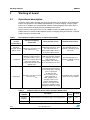
Initial settings for new battery
To give flexibility to the user to connect any Li-Ion battery to the demonstration board,
firmware provides an option to the user to program the battery capacity in the demonstration
board using a jumper switch and LEDs. If the user wants to program the maximum battery
capacity, use the following steps:
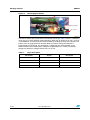
Figure 5.
Initial setting for new battery before power-on
3WITCH
&ITTHEJUMPER
,%$S
!-V
●
Set the J7 jumper between pin 1 and 2 before power-on, as shown in Figure 5
●
Connect either the adapter or the USB cable to power-on the board
●
Using the SW1, set the capacity of the battery. Pressing the switch once increases the
battery capacity in multiples of 300 mAh up to a maximum of 2100 mAH. The five levels
of LEDs are used to indicate the capacity of the battery
●
When the user first presses SW1 the D4 LED lights up, indicating 300 mAh. Press
again to set 600 mAh. The LED lights up according to BCD format. The user must
press the switch repeatedly to increase the capacity. The maximum allowed is 2100
mAH
●
If the user exceeds the limit, the D2 LED is red, indicating the maximum capacity the
user can enter as 2100 mAh. If the user wants to enter less capacity, the board should
be restarted and the correct capacity of the battery entered
●
Once the capacity is entered by pressing the switch, again set the jumper between pin
2 and 3, as shown in Figure 5, without powering off the demonstration board
●
When a battery capacity is programmed to the board the value is stored in the internal
flash of the microcontroller by EEPROM emulation
Now the 5 LEDs show the available capacity of the battery according to the programmed
capacity of the battery. Once the battery capacity is programmed, it is not necessary to
reconfigure again
Doc ID 15407 Rev 1
9/28
Working of board
Table 3.
Figure 6.
UM0678
J7 jumper setting
Jumper
Description
1-2
Set for normal operation once the capacity is entered
2-3
Enter the battery capacity
Open
Not allowed
Setting of jumpers after power-on
&ITTHEJUMPER
!-V
3.3
Battery charging and discharging in the case of the STw4102
The board supports the onboard J4 jumper to select the charging and discharging mode of
battery. By default the board supports charging mode.
Table 4.
10/28
J4 jumper setting
Jumper
Description
1-2
Set the jumper for discharging mode
2-3
Set the jumper for charging mode
Open
Charging mode, by default
Doc ID 15407 Rev 1
UM0678
Working of board
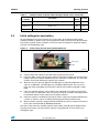
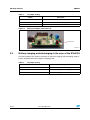
Figure 7.
Battery charging using the STw4102
#HARGINGMODE
'REEN,%$INDICATION
#APACITYINDICATIONOFBATTERY
!-V
The board is programmed to support a charging voltage of 4.2 V. When the battery voltage
approaches the programmable charge voltage (4.20 V), the charger enters into a constant
voltage charging mode and the charging current decreases. When the current level reaches
the end-of-charge level the battery is almost fully charged, and the charger enters
maintenance mode.
The gas gauge system monitors the battery charging and discharging. The demonstration
board has 5 LEDs which are used to show the present status of the battery charge with
respect to the mAH rating of the battery which was programmed by the user. as shown in
Table 5.
To discharge the battery connect the jumper between pin 1 and 2 of J4. Connect the load to
the J6 connector, as shown in Figure 7.
Table 5.
Battery capacity shown through level-LEDs D4 to D8
LEDs
Charging
Discharging
Status
Rcap %
Status
Rcap %
D7
ON
100 %
OFF
<80 %
D8
ON
>80 %
OFF
<60 %
D6
ON
>60 %
OFF
<40 %
D5
ON
>40 %
OFF
<20 %
D4
ON
>20 %
OFF
<10 %
In the case of charging when the Rcap % exceeds any level (as defined in Table 5), the
corresponding LEDs turn on and the other LEDs (above that level) keep on toggling. For
discharging when capacity drops to a certain level the corresponding LED turns off and the
other LEDs (below that level) keeps on toggling.
Doc ID 15407 Rev 1
11/28
Working of board
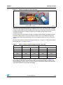
Figure 8.
UM0678
Discharging the battery
,OAD
&ITTHEJUMPERS
*CONNECTOR
!-V
Connect the load to the load terminals of the board, referring to Table 6. There is a MOSFET
which acts as a switch between load and battery. When the J4 jumper fits on pin 1 and 2 of
J4 the MOSFET is turned on by the microcontroller by reading the state of the jumper. The
battery starts to supply power to the load. When the battery voltage falls below the
programmed critical voltage, the discharging is stopped by the microcontroller. In the
demonstration board critical battery voltage is programmed to 3.1 V. When the battery
voltage falls below this voltage LED D2 turns on in red.
Table 6.
12/28
J6 pin description
Pin number
Jumper
Description
1
B+
Battery positive terminal
2
B-
Battery negative terminal
3
Load+
Load positive terminal
4
Gnd
Ground
Doc ID 15407 Rev 1
UM0678
4
Hardware design description
Hardware design description
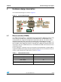
The hardware block diagram is shown in Figure 9.
Figure 9.
System block diagram
*4!'
#ONNECTOR
%3$
0ROTECTION
53"-INI
#ONNECTOR
!
34-
!
"
34W
-/3&%4
6OLTAGE
2EGULATOR
"ATTERY
#ONNECTOR
"ATTERY,OAD
#ONNECTOR
"
0OWER
*ACK
!-V
4.1
Microcontroller (STM32)
The STM32 microcontroller is a 32-bit MCU based on the popular ARM 32-bit Cortex™-M3
CPU, running at 72 MHz with a performance of 90 DMIPS with 1.25 DMIPS/MHz. The
microcontroller has single-cycle multiplication and hardware division. The device supports
low-power modes like sleep, stop, and also standby. The microcontroller has up to 9
communication interfaces which include two I2Cs (400 kHz), three USARTs (4.5 Mbps), two
SPIs (18 MHz), CAN 2.0B Active interface, and USB 2.0 (12 Mbps) full-speed interface. For
more details refer to the STM32 datasheet; 32-bit ARM Cortex MCU, and reference manual
at http://www.st.com.
For this application a minimum of one I2C to interface with the STw4102 is needed, USB to
support the USB-based charger and some general purpose IOs for user interface. The part
numbers used to develop this application are shown in Table 7.
Table 7.
Microcontroller details
Feature
Description
Sales type
STM32F103C6T6A
Package
LQFP-48 (7 x 7) mm
Flash - Kbytes
32
SRAM - Kbytes
10
Operating voltage
2.0 to 3.6 V
Doc ID 15407 Rev 1
13/28
Hardware design description
4.2
UM0678
Battery charger (STw4102)
The STw4102 is a standalone constant-current, constant-voltage (CCCV) linear charger
dedicated to Li-Ion batteries. The device has a dual-charging capability which uses the main
input adaptor (wall or car adapter) or a USB cable. The STw4102 contains an accurate gas
gauge based on a 13-bit AD converter and battery voltage monitor with a 7- to 12-bit AD
converter. For more details refer to the STw4102 datasheet; Dual USB/wall adapter Li-ion
battery charger with gas gauge, at http://www.st.com.
Table 8.
4.3
STw4102 details
Feature
Description
Order code
STW4102IQT
Package
QFN24
Operating voltage VUSB
4.25 to 5.5 V
Operating voltage VMAIN
4.25 to 16 V
ESD protection device
USBLC6-2P6 is a monolithic application specific device, dedicated to ESD protection of high
speed interfaces, such as USB 2.0, Ethernet links and video lines. For more details please
refer to the USBLC6-2P6 datasheet; Very low capacitance ESD protection, at
http://www.st.com.
Table 9.
4.4
USBLC6 details
Feature
Description
Order code
USBLC6-2P6
Package
SOT23-6L
Voltage regulator
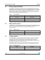
The LD2985A/Bxx is a 150 mA fixed-output voltage regulator. The ultra-low drop voltage
and the low quiescent current make them particularly suitable for low noise, low-power
applications, and in battery powered systems. For more details please refer to the
LD2985A/Bxx datasheet; Very low drop and low noise voltage regulator low ESR capacitor
compatible with inhibit function, at http://www.st.com.
The STw4102 device needs 3 V input for one of the input pins for proper operation. As the
STM32 device supports a voltage range from 2.6 to 5 V, 3 V was chosen for the design.
Table 10.
14/28
Voltage regulator
Feature
Description
Sales type
LD2985BM30R
Package
SOT23-5L
Doc ID 15407 Rev 1
UM0678
4.5
Hardware design description
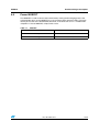
Power MOSFET
The MOSFET is used to connect the load to battery. During the discharging process the
microcontroller turns on the MOSFET so as to consume power from the battery. For more
details please refer to the STT3PF30L datasheet; P-Channel 30V 0.14 Ω - 3A SOT23-6L
STripFETTM II Power MOSFET, at http://www.st.com.
Table 11.
MOSFET
Feature
Description
Sales type
STT5PF20V
Package
SOT23-6L
Doc ID 15407 Rev 1
15/28
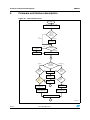
Firmware architecture description
5
UM0678
Firmware architecture description
Figure 10. Firmware flow chart
3TART
#ONFIGUREDEVICE34WAND
34-INREQUIREDCONFIGURATION
#HECKFORNEW
BATTERY
CAPACITYENTRY
*UMPER*
.OT
2EQUIRED
2EQUIRED
%NTERCAPACITY
OFNEWBATTERY
53"
7AITFOR53"
CONFIGURATION
#HECKFOR
0OWERSOURCE
3ET34WINFAST
CHARGEMODE
%NABLEANDCALIBRATEGASGAUGE
7ALL!DAPTER
!
#HECKFORCHARGING
DISCHARGING
*UMPER*
#HARGING
#HECKFOR
BATTERY
ABSENT
9%3
9%3
/.$2ED
.O
#HECKFOR
ENDOF
CHARGE
$ISCHARGING
1R
$ISCONNECTLOAD
FROMBATTERY
9%3
9%3
#HECKFOR
BATTERY
ABSENT
3HOWBATTERYFULL
CHARGED
#HECKFOR
CRITICAL
BATTERY
.O
.O
!
2EADCHARGE
ACCUMULATORDATA
2EADDISCHARGE
ACCUMULATOR
D
2CAP2CAP#AP
EXTRACTED-AX#AP
2CAP2CAPCAP
ACCUMULATED-AX#AP
3HOW2CAPTHROUGHSTATUS,%$S
!
!-V
16/28
Doc ID 15407 Rev 1
UM0678
Connectors and jumpers
6
Connectors and jumpers
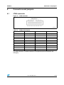
6.1
JTAG connector
Figure 11. JTAG connector
!-V
Table 12.
JTAG pin description
Pin number
Description
Pin number
Description
1
3.3 V power
2
3.3 V power
3
TRST
4
GND
5
TDI
6
GND
7
TMS
8
GND
9
TCK
10
GND
11
RTCK
12
GND
13
TDO
14
GND
15
nSRST
16
GND
17
DBGRQ
18
GND
19
DBGACK
20
GND
The JTAG connector is available onboard for re-programming the microcontroller and
debugging.
Doc ID 15407 Rev 1
17/28
Connectors and jumpers
6.2
UM0678
USB connector
The standard USB mini-B type (5-pin) connector is used. An additional 4 connections (pins
6-9 in the schematics) are connected to the body of the connector. Confirm that these pins
(shell/shield) are connected to the ground through an RC circuit. The maximum current
drawn by the board from the USB host/hub is less than 500 mA in any condition, to respect
the USB specifications.
Figure 12. Mini-B USB connector
!-V
Table 13.
6.3
USB connector pin description
Pin number
Description
Pin number
Description
1
VBUS(Power): +5 V
supply from USB bus
6
SHIELD
2
DM: USB D- signal
7
SHIELD
3
DP: USB D+ signal
8
SHIELD
4
--
9
SHIELD
5
GND: ground signal
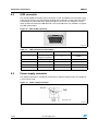
Power supply connector
The adaptor connector is available for connecting an external voltage source. An adaptor of
5 V DC can be used.
Figure 13. Power supply connector
6IEWEDFROMFRONT
!-V
18/28
Doc ID 15407 Rev 1
UM0678
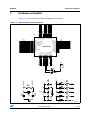
7
Hardware schematic
Hardware schematic
Figure 14, 15 and 16 shows the schematic diagrams for the board.
-7$*B-17567B3%
-7$*B-7'2B3%
-7$*B-7',B3$
-7$*B-7&.B3$
%227
,&B6'$B3%
,&B6&/B3%
9%$7
3&B$17B7$03
3&B26&B,1
3&B26&B287
3'B26&B,1
3'B26&B287 670)&7$
1567
966$
9''$
3$B:.83
3$
3$
9''B
966B
3$
3$
3$
3$
3$
3$
3%
3%
3%
3%
3$
3$
3$
3$
3$
3%
3%
3%
3%
3%
966B
9''B
9
*1'
-7$*B-706B3$
86%'3B3$
86%'0B3$
(2&+*B3$
3:5'(7(&71B3$
&.+=B3$
*1'
9
%227B3%
3%
3$
5(6(71B3$
3$
3$
3$
9
3&
3&
3&
26&B,1
26&B287
Q567
*1'
9
3$
67'%<B3$
86%B38B3$
9''B
966B
3%
3%
%227
3%
3%
3%
3%
3%
3$
3$
8
9
*1'
3%
Figure 14. Microcontroller section schematic
9
5
'
5
&
Q)
5
'
/('
&
Q)
5
'
/('
5
'
/('
*1'
5
'
/('
'
/('
26&B287
5
0
9
9
&
Q)
&
Q)
3$
9
&
S)
3$
&
Q)
<
0+]
3&
3%
&
S)
Doc ID 15407 Rev 1
3&
26&B,1
&$%,&
!-V
19/28
Hardware schematic
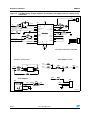
UM0678
Figure 15. STw4102 battery charger, MOSFET_STT5PF20V, wall adaptor and anti tamper circuit
schematics
&21
%
%
-
3:5'(7(&71B3$
(2&+*B3$
&
X)
5
N
3$
5
N
5
N
9
,&B6&/B3%
,&B6'$B3%
5(6(71B3$
86%3:5
,&*
,&*
3:5'(7(&71
%$77
(2&+*
%$776(16(
&95()
,6(7
/'2'59
/'2)%
67Z
&9,6
&.+=
67'%<
9,2
6&/
9287
6'$
6(16(
5(6(71
0$,1
7(67
86%9
'5,9(5
&
Q)
5
PLOL2+0
&
X)
5
.
&
X)
&.+=B3$
67'%<B3$
%
%
/2$'
-
#
#
-0"%
-0"%
&21
:$//B$'375
5
N
3$
8
*1'
&
Q)
*1'
347"!44%29#(!2'%2
!NTITAMPERCIRCUIT
-/3&%4?3440&6
9
5
N
3&
5
N
6:
8
/2$'
3%
37&
/
5
'
'
*
'
'
6
&
*1'
5
N
9
6:B3%B6367
%
Q)
6773)9627/
5
N
7ALLADAPTOR
9
-
5
N
'
:$//B$'375
*1'
9,1
6736/8
3$
-
&21
!-V
20/28
Doc ID 15407 Rev 1
Doc ID 15407 Rev 1
'%*$&.
'%*54
5
N
5
N
5
N
5
N
5
N
*1'
5
N
5
5
N
&
Q)
5
0
6+(//
6+(//
6+(//
6+(//
-
86%B9&&
86%'0
86%'3
,'
86%B*1'
86%9
86%9
86%B'0
'
9,1
86%B'3
86%B'0
86%9
*1'
6736/8
,1
/'$;;
*1'
287
,1+,%,7
5
N
%<3$66
8
53"3%#4)/.
&
Q)
&21
%227B3%
9,1
Q567
-7$*B-7'2B3%
57&.
-7$*B-7&.B3$
-7$*B-706B3$
-7$*B-7',B3$
-7$*B-17567B3%
9
5
N
9
5
N
9
,2
,2
&
Q)
86%B38B3$
86%B'3
86%B'0
5
&
Q)
5
N
&
X)9
5
N
5
&
S)
86%'3B3$
&
S)
86%'0B3$
&
Q)
0/7%23500,9
&21
-
86%/&3
,2
*1'
,2
8
86%9
9
5
-7$*B&211
-
*4!'#/..%#4/ 2
%227
-
9
Q567
9%86
"//4*5-0%23
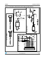
UM0678
Hardware schematic
Figure 16. Boot jumpers, JTAG connector, power supply and USB schematics
!-V
21/28
Bill of materials
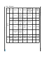
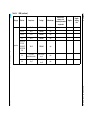
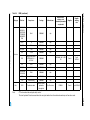
Table 14.
BOM
Category
Doc ID 15407 Rev 1
Ref. des.
Comp. descr.
Package
Manufacturer
Manufacturer’s
ordering code /
orderable part number
or equivalent
U1
Voltage regulator IC
LD2985BM30R
SOT23-5L
STMicroelectronics
LD2985BM30R
U2
ESD protection device
USBLC6-2P6
SOT23-6L
STMicroelectronics
USBLC6-2P6
U3
Dual USB/wall adapter
Li-ion battery charger
with gas gauge STw4102
QFN24
STMicroelectronics
STW4102IQT
U4
Microcontroller STM32
Family, ARM-based 32bit MCU
LQFP48
STMicroelectronics
STM32F103C6T6A
U7
P-Channel, power
MOSFET STT5PF20V
SOT23-6L
STMicroelectronics
STT5PF20V
D1,D3
Low-drop power
Schottky rectifier
STPS1L30U
SMA
STMicroelectronics
STPS1L30U
Y1
Quartz crystal 8 MHz
11.35 mm x 4.35
mm, SS4
Jauch
Q 8.0-SS4-30-30/30
ST devices
Crystal and
oscillator
UM0678
7.1
Supplier
Supplier
ordering
code
Hardware schematic
22/28
Category
BOM (continued)
Doc ID 15407 Rev 1
Comp. descr.
Package
Manufacturer
Manufacturer’s
ordering code /
orderable part number
or equivalent
J1
JTAG connector
Box Header,
Straight 20way,
2x10pin, 2.54 mm
x 2.54 mm pitch
MULTICOMP
MC9A12-2034
J2
Mini USB connector
SMD USB Mini-B
type connector
KYCON
KMBX-SMT-5S-S-30TR
J3,J4,J7
3-pin jumper
Jumper 3 pin,
1x3way, 2.54 mm
pitch
SAMTEC
TSW-103-23-G-S
J5
Terminal block
2-pin terminal
block, screw
termination
5.08 mm pitch
PHOENIX
CONTACT
Part# 1711725
Farnell
Part# 3041165
J6
Rechargeable battery
connector
Header 4 pin,
1x4way, right
angle, 2.54 mm
pitch
Any
J8
Power jack 2.5 mm
Socket, DC power,
2.5 mm
CLIFF electronic
components
DC10B
Farnell
Part# 224960
D4,D5,D6,D7,
D8
SMD1206
OSRAM
LGN971
Farnell
Part# 1226371
5
D2
Dual color LED, common
anode
Through hole
Any
Ref. des.
Connectors
and jumpers
Supplier
Supplier
ordering
code
Farnell
Part# 1099258
Hardware schematic
23/28
Table 14.
1
LEDs
UM0678
Category
Capacitors
BOM (continued)
Doc ID 15407 Rev 1
Ref. des.
Comp. descr.
Package
Manufacturer
C6,C7
15 pF
SMD0805
Any
C9,C12
20 pF
SMD0805
Any
C3,C8
4.7 nF
SMD0805
Any
C1
10 nF
SMD0805
Any
C4,C5,C10,
C11,C14,
C15,C16,C17,
C18,C19,C20,
C23
100 nF
SMD0805
Any
C2
4.7 µF/10 V
tantalum/electrolytic
EIA 3216-18/
size A
Any
C13
18 µF
EIA 3528-21/
size B
Any
Manufacturer’s
ordering code /
orderable part number
or equivalent
Supplier
Supplier
ordering
code
UM0678
Table 14.
Hardware schematic
24/28
Category
Doc ID 15407 Rev 1
Resistors
Misc
Note:
BOM (continued)
Ref. des.
Comp. descr.
Package
Manufacturer
R1,R2,R3,R4,
R6,R9,R13,
R14,R15,R16,
R17,R20,R22,
R34,R36,R37,
R38
10 kΩ
SMD0805
Any
R5,R7
0
SMD0805
Any
R8,R10
22 Ω
SMD0805
Any
R11,R18
1 kΩ
SMD0805
Any
R12
1.5 kΩ
SMD0805
Any
R19
RESISTOR, METAL
STRIP, 0.03 Ω 1 %
0.12 5 W
SMD0805
R21
15 kΩ
SMD0805
Any
R23,R24
4.7 kΩ
SMD0805
Any
R25,R29,R30,
R31,R32,R33
470 Ω
SMD0805
Any
R28
500 Ω
SMD0805
Any
PTC
500 mA rating
SMD0805
Any
SW1
Pushbutton switch
(6 mm X 6 mm)
pushbutton,
through hole
Tyco Electronics
Manufacturer’s
ordering code /
orderable part number
or equivalent
Supplier
Supplier
ordering
code
WSL-0805 .03 1 % EB
E3
Farnell
Part#
1107335
FSM2JH
Farnell
Part# 1555981
Hardware schematic
25/28
Table 14.
PTC not mounted onboard, replaced by a short
The term “equivalent” has been used where the exact part number from the mentioned vendor may not have been used.
UM0678
References
8
26/28
UM0678
References
1.
STw4102 datasheet
2.
STM32 datasheet; 32-bit ARM Cortex MCU
Doc ID 15407 Rev 1
UM0678
9
Revision history
Revision history
Table 15.
Document revision history
Date
Revision
27-Jul-2010
1
Changes
Initial release.
Doc ID 15407 Rev 1
27/28
UM0678
Please Read Carefully:
Information in this document is provided solely in connection with ST products. STMicroelectronics NV and its subsidiaries (“ST”) reserve the
right to make changes, corrections, modifications or improvements, to this document, and the products and services described herein at any
time, without notice.
All ST products are sold pursuant to ST’s terms and conditions of sale.
Purchasers are solely responsible for the choice, selection and use of the ST products and services described herein, and ST assumes no
liability whatsoever relating to the choice, selection or use of the ST products and services described herein.
No license, express or implied, by estoppel or otherwise, to any intellectual property rights is granted under this document. If any part of this
document refers to any third party products or services it shall not be deemed a license grant by ST for the use of such third party products
or services, or any intellectual property contained therein or considered as a warranty covering the use in any manner whatsoever of such
third party products or services or any intellectual property contained therein.
UNLESS OTHERWISE SET FORTH IN ST’S TERMS AND CONDITIONS OF SALE ST DISCLAIMS ANY EXPRESS OR IMPLIED
WARRANTY WITH RESPECT TO THE USE AND/OR SALE OF ST PRODUCTS INCLUDING WITHOUT LIMITATION IMPLIED
WARRANTIES OF MERCHANTABILITY, FITNESS FOR A PARTICULAR PURPOSE (AND THEIR EQUIVALENTS UNDER THE LAWS
OF ANY JURISDICTION), OR INFRINGEMENT OF ANY PATENT, COPYRIGHT OR OTHER INTELLECTUAL PROPERTY RIGHT.
UNLESS EXPRESSLY APPROVED IN WRITING BY AN AUTHORIZED ST REPRESENTATIVE, ST PRODUCTS ARE NOT
RECOMMENDED, AUTHORIZED OR WARRANTED FOR USE IN MILITARY, AIR CRAFT, SPACE, LIFE SAVING, OR LIFE SUSTAINING
APPLICATIONS, NOR IN PRODUCTS OR SYSTEMS WHERE FAILURE OR MALFUNCTION MAY RESULT IN PERSONAL INJURY,
DEATH, OR SEVERE PROPERTY OR ENVIRONMENTAL DAMAGE. ST PRODUCTS WHICH ARE NOT SPECIFIED AS "AUTOMOTIVE
GRADE" MAY ONLY BE USED IN AUTOMOTIVE APPLICATIONS AT USER’S OWN RISK.
Resale of ST products with provisions different from the statements and/or technical features set forth in this document shall immediately void
any warranty granted by ST for the ST product or service described herein and shall not create or extend in any manner whatsoever, any
liability of ST.
ST and the ST logo are trademarks or registered trademarks of ST in various countries.
Information in this document supersedes and replaces all information previously supplied.
The ST logo is a registered trademark of STMicroelectronics. All other names are the property of their respective owners.
© 2010 STMicroelectronics - All rights reserved
STMicroelectronics group of companies
Australia - Belgium - Brazil - Canada - China - Czech Republic - Finland - France - Germany - Hong Kong - India - Israel - Italy - Japan Malaysia - Malta - Morocco - Philippines - Singapore - Spain - Sweden - Switzerland - United Kingdom - United States of America
www.st.com
28/28
Doc ID 15407 Rev 1