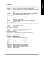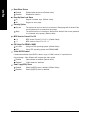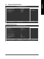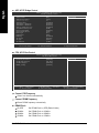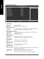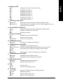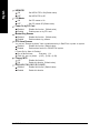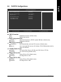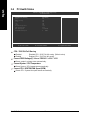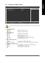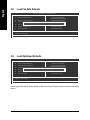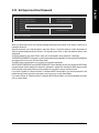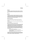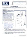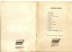
1
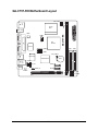
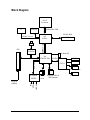
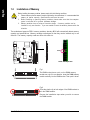
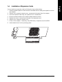
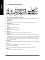
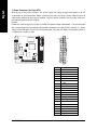
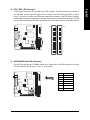
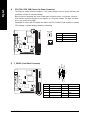
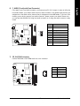
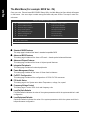
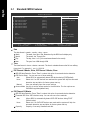
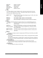
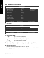
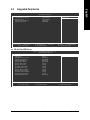
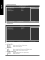
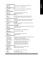
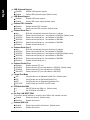
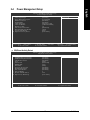
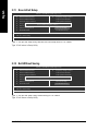
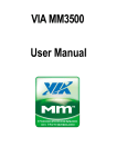
GA-C7V7-RH VIA C7 Processor Motherboard User's Manual Rev. 100 12ME-C7V7RH-1001R Table of Contents GA-C7V7-RH Motherboard Layout ................................................................................ 3 Block Diagram ................................................................................................................ 4 Chapter 1 Hardware Installation ..................................................................................... 5 1-1 1-2 1-3 Considerations Prior to Installation .................................................................... 5 Feature Summary ............................................................................................ 6 Installation of Memory ...................................................................................... 8 1-4 1-5 1-6 Installation of Expansion Cards ........................................................................ 9 I/O Back Panel Introduction ........................................................................... 10 Connectors Introduction ................................................................................... 11 Chapter 2 BIOS Setup ................................................................................................ 19 The Main Menu (For example: BIOS Ver. :F4) ........................................................ 20 2-1 2-2 2-3 2-3 Standard CMOS Features ............................................................................. 22 Advanced BIOS Features .............................................................................. 24 Advanced Chipset Features ........................................................................... 27 Integrated Peripherals ..................................................................................... 33 2-4 2-5 2-6 2-7 Power Management Setup ............................................................................. 37 PnP/PCI Configurations ................................................................................. 41 PC Health Status ........................................................................................... 42 Frequency / Voltage Control ........................................................................... 43 2-8 2-9 2-10 2-11 Load Fail-Safe Defaults ................................................................................... 44 Load Optimized Defaults ................................................................................. 44 Set Supervisor/User Password ..................................................................... 45 Save & Exit Setup ......................................................................................... 46 2-12 Exit Without Saving ....................................................................................... 46 -2- GA-C7V7-RH Motherboard Layout DDRII KB MS CPU_FAN VIA C7 CPU RCA SV BIOS VGA GA-C7V7-RH COMB LPT VIA CN700 COMA IT8712 ATX IDE1 IDE2 F_USB2 F_USB1 USB CLR_CMOS RTL8100C USB LAN VT8237R Plus BAT F_AUDIO CD_IN AUDIO SPDIF_IO SATA2 SATA1 CODEC SYS_FAN F_PANEL PCI1 -3- Block Diagram VIA C7 Processor TV VIA CN700 S-Video / AV out 533/400 MHz DDRII 66MHz V_Link RJ45 1 PCI 533/400 MHz FSB VGA Port RTL8100C 2 Serial ATA VIA VT8237R Plus LPC BUS AC97 Link IT8712 8 USB Ports LINE-OUT MIC LINE-IN LPT Port PS/2 KB/Mouse 6 Channel CODEC PCICLK (33MHz) BIOS -4- ATA33/66/100/133 IDE Channels COM Ports 1-1 English Chapter 1 Hardware Installation Considerations Prior to Installation Preparing Your Computer The motherboard contains numerous delicate electronic circuits and components which can become damaged as a result of electrostatic discharge (ESD). Thus, prior to installation, please follow the instructions below: 1. Please turn off the computer and unplug its power cord. 2. When handling the motherboard, avoid touching any metal leads or connectors. 3. It is best to wear an electrostatic discharge (ESD) cuff when handling electronic components (CPU, RAM). 4. Prior to installing the electronic components, please have these items on top of an antistatic pad or within a electrostatic shielding container. 5. Please verify that the power supply is switched off before unplugging the power supply connector from the motherboard. Installation Notices 1. Prior to installation, please do not remove the stickers on the motherboard. These stickers are required for warranty validation. 2. Prior to the installation of the motherboard or any hardware, please first carefully read the information in the provided manual. 3. Before using the product, please verify that all cables and power connectors are connected. 4. To prevent damage to the motherboard, please do not allow screws to come in contact with the motherboard circuit or its components. 5. Please make sure there are no leftover screws or metal components placed on the motherboard or within the computer casing. 6. Please do not place the computer system on an uneven surface. 7. Turning on the computer power during the installation process can lead to damage to system components as well as physical harm to the user. 8. If you are uncertain about any installation steps or have a problem related to the use of the product, please consult a certified computer technician. Instances of Non-Warranty 1. 2. 3. 4. 5. 6. Damage due to natural disaster, accident or human cause. Damage as a result of violating the conditions recommended in the user manual. Damage due to improper installation. Damage due to use of uncertified components. Damage due to use exceeding the permitted parameters. Product determined to be an unofficial Gigabyte product. -5- Hardware Installation English 1-2 Feature Summary CPU Front Side Bus Chipset LAN Audio Storage O.S Support Memory Expanstion Slots Internal Connectors Rear Panel I/O GA-C7V7-RH Motherboard VIA C7 processor 533 / 400MHz Northbridge: VIA CN700 Southbridge: VIA 8237R Plus Onboard RTL8100C chip (10/100 Mbit) Realtek ALC653 CODEC Supports 2 / 4 / 6 channel audio Supports Line In ; Line Out ; MIC SPDIF Out connection CD In connection VIA 8237R Plus - 1 FDD connector, allowing connection of 2 FDD device - 2 IDE connectors (IDE1, IDE2) with UDMA 33/ATA 66/ATA 100/ATA 133 support, allowing connection of 4 IDE devices - 2 SATA connectors (SATA1/SATA2), allowing connection of 2 SATA devices Microsoft Windows 2000/XP 1 DDRII DIMM memory slots Supports 1.8V DDRII DIMMs 1 PCI slots 1 20-pin ATX power connector 2 IDE connectors 2 SATA connectors 1 CPU fan connector 1 system fan connector 1 front panel connector 1 front audio connector 1 CD In connector 2 USB 2.0/1.1 connectors for additional 4 USB 2.0/1.1 ports by cables 1 SPDIF In/Out connector 1 PS/2 keyboard port 1 PS/2 mouse port 1 parallel port 1 COMA port 1 VGA port 1 TV Out (Optional) 1 S-Video port (Optional) 4 USB 2.0/1.1 ports 1 RJ-45 port 3 audio jacks (Line In / Line Out / MIC In) -6- BIOS Form Factor IT8712 chip System voltage detection CPU / System temperature detection CPU / System fan speed detection CPU warning temperature CPU / System fan failure warning Supports CPU / System Smart Fan function Use of licensed AWARD BIOS Mini-ITX form factor; 17.0cm x 17.0cm -7- English I/O Control Hardware Monitor Hardware Installation English 1-3 Installation of Memory Before installing the memory modules, please comply with the following conditions: 1. Please make sure that the memory used is supported by the motherboard. It is recommended that memory of similar capacity, specifications and brand be used. 2 . Before installing or removing memory modules, please make sure that the computer power is switched off to prevent hardware damage. 3 . Memory modules have a foolproof insertion design. A memory module can be installed in only one direction. If you are unable to insert the module, please switch the direction. The motherboard supports DDR II memory modules, whereby BIOS will automatically detect memory capacity and specifications. Memory modules are designed so that they can be inserted only in one direction. The memory capacity used can differ with each slot. notch DDRII memory module Fig.1 The DIMM socket has a notch, so the DIMM memory module can only fit in one direction. Insert the DIMM memory module vertically into the DIMM socket. Then push it down. Fig.2 Close the plastic clip at both edges of the DIMM sockets to lock the DIMM module. Reverse the installation steps when you wish to remove the DIMM module. GA-C7V7-RH Motherboard -8- Installation of Expansion Cards You can install your expansion card by following the steps outlined below: 1. Read the related expansion card's instruction document before installing the expansion card into the computer. 2. Remove your computer's chassis cover, screws and slot bracket from the computer. 3. Press the expansion card firmly into expansion slot in motherboard. 4. Be sure the metal contacts on the card are indeed seated in the slot. 5. Replace the screw to secure the slot bracket of the expansion card. 6. Replace your computer's chassis cover. 7. Power on the computer, if necessary, setup BIOS utility of expansion card from BIOS. 8. Install related driver from the operating system. -9- Hardware Installation English 1-4 English 1-5 I/O Back Panel Introduction PS/2 Keyboard and PS/2 Mouse Connector To install a PS/2 port keyboard and mouse, plug the mouse to the upper port (green) and the keyboard to the lower port (purple). Parallel Port The parallel port allows connection of a printer, scanner and other peripheral devices. S-Video port TV can be connected to S-Video port. TV Out TV can be connected to TV Out port. VGA Port Monitor can be connected to VGA port. Serial Port Devices like mouses, modems, and etc. can be connected to Serial port. USB port Before you connect your device(s) into USB connector(s), please make sure your device(s) such as USB keyboard, mouse, scanner, zip, speaker...etc. have a standard USB interface. Also make sure your OS supports USB controller. If your OS does not support USB controller, please contact OS vendor for possible patch or driver upgrade. For more information please contact your OS or device(s) vendors. LAN Port The provided Internet connection is fast Ethernet, providing data transfer speeds of 10/100Mbps. Line In Devices like CD-ROM, walkman etc. can be connected to Line In jack. Line Out (Front Speaker Out) Connect the stereo speakers, earphone or front surround channels to this connector. MIC In Microphone can be connected to MIC In jack. GA-C7V7-RH Motherboard - 10 - Connectors Introduction English 1-6 9 5 1 10 12 2 11 7 6 4 5 8 1) 2) 3) 4) 5) 6) ATX IDE1/ IDE2 SATA1 / SATA2 CPU_FAN / SYS_FAN F_PANEL F_AUDIO 3 7) 8) 9) 10) 11) 12) - 11 - CD_IN SPDIF_IO COMB F_USB1 / F_USB2 BAT CLR_CMOS Hardware Installation English 1) Power Connector (2x10 pin ATX ) With the use of the power connector, the power supply can supply enough stable power to all the components on the motherboard. Before connecting the power connector, please make sure that all components and devices are properly installed. Align the power connector with its proper location on the motherboard and connect it tightly. Caution! Please use a power supply that is able to handle the system voltage requirements. It is recommended that a power supply that can withstand high power consumption be used (300W or greater). If a power supply is used that does not provide the required power, the result can lead to an unstable system or a system that is unable to start. 10 20 1 11 Pin No. GA-C7V7-RH Motherboard - 12 - Definition 1 3.3V 2 3 3.3V GND 4 +5V 5 GND 6 7 +5V GND 8 Power Good 9 5V SB (stand by +5V) 10 11 +12V 3.3V 12 -12V 13 GND 14 15 PS_ON(soft on/off) GND 16 GND 17 GND 18 19 -5V +5V 20 +5V An IDE device connects to the computer via an IDE connector. One IDE connector can connect to one IDE cable, and the single IDE cable can then connect to two IDE devices (hard drive or optical drive). If you wish to connect two IDE devices, please set the jumper on one IDE device as Master and the other as Slave (for information on settings, please refer to the instructions located on the IDE device). Before attaching the IDE cable, please take note of the foolproof groove in the IDE connector. 40 39 2 1 IDE1 IDE2 3) SATA1/SATA2 (Serial ATA Connector,) Serial ATA can provide up to 150MB/s transfer rate. Please refer to the BIOS setting for the Serial ATA and install the proper driver in order to work properly. Pin No. 7 - 13 - 1 Definition 1 2 GND TXP 3 TXN 4 GND 5 6 RXN RXP 7 GND Hardware Installation English 2) IDE1 / IDE2 (IDE Connector) CPU_FAN / SYS_FAN (Cooler Fan Power Connector) The cooler fan power connector supplies a +12V power voltage via a 3-pin power connector and possesses a foolproof connection design. Most coolers are designed with color-coded power connector wires. A red power connector wire indicates a positive connection and requires a +12V power voltage. The black connector wire is the ground wire (GND). Remember to connect the CPU/system fan cable to the CPU_FAN/SYS_FAN connector to prevent CPU damage or system hanging caused by overheating. CPU_FAN Pin No. 1 1 Definition GND 2 +12V 3 Sense 1 SYS_FAN F_PANEL (Front Panel Connector) MSG+ MSGPWRSW GND ACT_LED- 5) 10 9 GA-C7V7-RH Motherboard RESET ACT_LED+ HDGND 2 1 HD+ English 4) Pin No. 1 Definition HD_LED+ Pin No. 2 MSGLED+ 3 HD_LED- 4 MSGLED- 5 GND 7 9 RESET ACT_LED+ 6 8 PWRSW GND 10 ACT_LED- - 14 - Definition If you want to use Front Audio connector, you must remove 5-6, 9-10 Jumper. In order to utilize the front audio header, your chassis must have front audio connector. Also please make sure the pin assigments on the cable are the same as the pin assigments on the MB header. To find out if the chassis you are buying support front audio connector, please contact your dealer.Please note, you can have the alternative of using front audio connector or of using rear audio connector to play sound. Pin No. 1 10 9 2 1 Definition MIC 2 GND 3 MIC_BIAS 4 5 POWER FrontAudio(R) 6 Rear Audio (R)/ Return R 7 NC 8 9 No Pin FrontAudio (L) 10 Rear Audio (L)/ Return L 7) CD_IN (CD IN Connector) Connect CD-ROM or DVD-ROM audio out to the connector. Pin No. 1 - 15 - Definition 1 2 CD-L GND 3 GND 4 CD-R Hardware Installation English 6) F_AUDIO (Front Audio Panel Connector) English 8) SPDIF_IO (SPDIF In/Out) The SPDIF output is capable of providing digital audio to external speakers or compressed AC3 data to an external Dolby Digital Decoder. Use this feature only when your stereo system has digital input function. Use SPDIF IN feature only when your device has digital output function. Be careful with the polarity of the SPDIF_IO connector. Check the pin assignment carefully while you connect the SPDIF cable, incorrect connection between the cable and connector will make the device unable to work or even damage it. For optional SPDIF cable, please contact your local dealer. 1 Pin No. 1 Definition VCC 2 SPDIF_O 3 GND 9) COMB (COMB Connector) Be careful with the polarity of the COMB connector. Check the pin assignment carefully while you connect the COMB cable, incorrect connection between the cable and connector will make the device unable to work or even damage it. For optional COMB cable, please contact your local dealer. 10 2 GA-C7V7-RH Motherboard - 16 - 9 1 Pin No. Definition 1 2 NDCDBNSINB 3 NSOUTB 4 NDTRB- 5 6 GND NDSRB- 7 NRTSB- 8 NCTSB- 9 10 NRIBNo Pin Be careful with the polarity of the front USB connector. Check the pin assignment carefully while you connect the front USB cable, incorrect connection between the cable and connector will make the device unable to work or even damage it. For optional front USB cable, please contact your local dealer. Pin No. Definition 1 Power (5V) 2 Power (5V) 3 4 USB DXUSB Dy- 5 USB DX+ 6 USB Dy+ 7 8 GND GND 1 9 10 2 9 No Pin 10 NC 11) BAT (Battery) Danger of explosion if battery is incorrectly replaced. Replace only with the same or equivalent type recommended by the manufacturer. Dispose of used batteries according to the manufacturer's instructions. If you want to erase CMOS... 1. Turn off the computer and unplug the power cord. 2. Gently take out the battery and put it aside for about one minute. (Or you can use a metal object to connect the positive and negative pins in the battery holder to makethem short for five seconds.) 3. Re-install the battery. 4. Plug the power cord in and turn on the computer. - 17 - Hardware Installation English 10) F_ USB1 / F_USB2 (Front USB Connector) English 12) CLR_CMOS (Clear CMOS) You may clear the CMOS data to its default values by this header. To clear CMOS, temporarily short the two pins. Default doesn't include the jumper to avoid improper use of this header. Open: Normal Short: Clear CMOS GA-C7V7-RH Motherboard - 18 - BIOS (Basic Input and Output System) includes a CMOS SETUP utility which allows user to configure required settings or to activate certain system features. The CMOS SETUP saves the configuration in the CMOS SRAM of the motherboard. When the power is turned off, the battery on the motherboard supplies the necessary power to the CMOS SRAM. When the power is turned on, pressing the <Del> button during the BIOS POST (Power-On Self Test) will take you to the CMOS SETUP screen. CONTROL KEYS < >< >< <Enter> <Esc> >< <Page Up> <Page Down> <F1> <F2> <F5> <F6> <F7> <F9> <F10> > Move to select item Select Item Main Menu - Quit and not save changes into CMOS Status Page Setup Menu and Option Page Setup Menu - Exit current page and return to Main Menu Increase the numeric value or make changes Decrease the numeric value or make changes General help, only for Status Page Setup Menu and Option Page Setup Menu Item Help Restore the previous CMOS value from CMOS, only for Option Page Setup Menu Load the Fail-Salf Defaults Load the Optimized Defaults System Information Save all the CMOS changes, only for Main Menu Main Menu The on-line description of the highlighted setup function is displayed at the bottom of the screen. Status Page Setup Menu / Option Page Setup Menu Press <F1> to pop up a small help window that describes the appropriate keys to use and the possible selections for the highlighted item. To exit the Help Window press <Esc>. Because BIOS flashing is potentially risky, please do it with caution and avoid inadequate operation that may result in system malfunction. - 19 - BIOS Setup English Chapter 2 BIOS Setup English The Main Menu (For example: BIOS Ver. :F4) Once you enter Phones-Award BIOS CMOS Setup Utility, the Main Menu (as figure below) will appear on the screen. Use arrow keys to select among the items and press <Enter> to accept or enter the sub-menu. Phoenix- AwardBIOS CMOS Setup Utility Standard CMOS Features Frequency/Voltage Control Advanced BIOS Features Load Fail-Safe Defaults Advanced Chipset Features Load Optimized Defaults Integrated Peripherals Set Supervisor Password Power Management Setup Set User Password PnP/PCI Configurations Save & Exit Setup PC Health Status Exit Without Saving ESC: Quit F10: Save & Exit Setup : Select Item Time, Date, Hard Disk Type... Standard CMOS Features This setup page includes all the items in standard compatible BIOS. Advanced BIOS Features This setup page includes all the items of Phoenix - Award special enhanced features. Advanced Chipset Features This setup page includes all the items of chipset special features. Integrated Peripherals This setup page includes all onboard peripherals. Power Management Setup This setup page includes all the items of Green function features. PnP/PCI Configuration This setup page includes all the configurations of PCI & PnP ISA resources. PC Health Status This setup page is the System auto detect Temperature, voltage, fan, speed. Frequency/Voltage Control This setup page is control CPU clock and frequency ratio. Load Fail-Safe Defaults Fail-Safe Defaults indicates the value of the system parameters which the system would be in safe configuration. Load Optimized Defaults Optimized Defaults indicates the value of the system parameters which the system would be in best performance configuration. GA-C7V7-RH Motherboard - 20 - Change, set, or disable password. It allows you to limit access to the system and Setup, or just to Setup. Set User Password Change, set, or disable password. It allows you to limit access to the system. Save & Exit Setup Save CMOS value settings to CMOS and exit setup. Exit Without Saving Abandon all CMOS value changes and exit setup. - 21 - BIOS Setup English Set Supervisor Password English 2-1 Standard CMOS Features Phoenix- AwardBIOS CMOS Setup Utility Standard CMOS Features Date (mm:dd:yy) Time (hh:mm:ss) Tue, Mar 15 2006 14:42:37 Item Help Menu Level IDE Channel 0 Master IDE Channel 0 Slave IDE Channel 1 Master IDE Channel 1 Slave IDE Channel 2 Master IDE Channel 3 Master [None] [None] [None] [None] [None] [None] Change the day, month, year <Week> Sun. to Sat. <Month> Jan. to Dec. Video Halt On [EGA/VGA] [All, But Keyboard] Base Memory Extended Memory Total Memory 640K 511M 512M : Move Enter: Select F5: Previous Values +/-/PU/PD: Value F6: Fail-Safe Defaults <Day> 1 to 31 (or maximum allowed in the month) <Year> 1999 to 2098 F10: Save ESC: Exit F1: General Help F7: Optimized Defaults Date The date format is <week>, <month>, <day>, <year>. Week The week, from Sun to Sat, determined by the BIOS and is display only Month The month, Jan. Through Dec. Day The day, from 1 to 31 (or the maximum allowed in the month) Year The year, from 1999 through 2098 Time The times format in <hour> <minute> <second>. The time is calculated base on the 24-hour militarytime clock. For example, 1 p.m. is 13:00:00. IDE Channel 0 Master, Slave, IDE Channel 1 Master, Slave IDE HDD Auto-Detection Press "Enter" to select this option for automatic device detection. IDE Device Setup. You can use one of three methods: Auto Allows BIOS to automatically detect IDE devices during POST(default) None Select this if no IDE devices are used and the system will skip the automatic detection step and allow for faster system start up. Manual User can manually input the correct settings Access Mode Use this to set the access mode for the hard drive. The four options are: CHS/LBA/Large/Auto(default:Auto) IDE Channel 2/3 Master IDE HDD Auto-Detection Press "Enter" to select this option for automatic device detection. Extended IDE Drive SATA devices setup. You can use one of two methods: Auto Allows BIOS to automatically detect SATA IDE devices during POST. (Default value) None Select this if no SATA IDE devices are used and the system will skip the automatic detection step and allow for faster system start up. Capacity Capacity of currently installed hard disk. GA-C7V7-RH Motherboard - 22 - Number of cylinders Number of heads Write precomp Landing zone Number of sectors English Cylinder Head Precomp Landing Zone Sector Video The category detects the type of adapter used for the primary system monitor that must match your video display card and monitor. Although secondary monitors are supported, you do not have to select the type in setup. EGA / VGA Enhanced Graphics Adapter/Video Graphics Array. For EGA, VGA, SVGA, CGA 40 CGA 80 MONO or PGA monitor adapters. Color Graphics Adapter, power up in 40 column mode. Color Graphics Adapter, power up in 80 column mode. Monochrome adapter, includes high resolution monochrome adapters. Halt on The category determines whether the computer will stop if an error is detected during power up. No Errors The system boot will not stop for any error that may be detected and you will be prompted. All Errors Whenever the BIOS detects a non-fatal error the system will be stopped. All, But Keyboard The system boot will not stop for a keyboard error; it will stop for all other errors. (Default value) All, But Diskette The system boot will not stop for a disk error; it will stop for all other errors. All, But Disk/Key The system boot will not stop for a keyboard or disk error; it will stop for all other errors. Memory The category is display-only which is determined by POST (Power On Self Test) of the BIOS. Base Memory The POST of the BIOS will determine the amount of base (or conventional) memory installed in the system. The value of the base memory is typically 512K for systems with 512K memory installed on the motherboard, or 640K for systems with 640K or more memory installed on the motherboard. Extended Memory The BIOS determines how much extended memory is present during the POST. This is the amount of memory located above 1 MB in the CPU's memory address map. Total Memory This item displays the memory size that used. - 23 - BIOS Setup English 2-2 Advanced BIOS Features Phoenix- AwardBIOS CMOS Setup Utility Advanced BIOS Features CPU Feature Hard Disk Boot Priority Virus Warning BIOS Flash Protectin CPU L1 & L2 Cache CPU L2 Cache ECC Checking Quick Power On Self Test First Boot Device Second Boot Device Third Boot Device Boot Other Device Boot Up Num Lock Status Security Option MPS Version Control For OS OS Select For DRAM > 64MB Video BIOS Shadow Small Logo(EPA) Show : Move Enter: Select F5: Previous Values [Press Enter] [Press Enter] [Disabled] [Auto] [Enabled] [Enabled] [Enabled] [Hard Disk] [USB-FDD] [CDROM] [Enabled] [On] [Setup] [1.4] [Non-OS2] [Enabled] [Disabled] +/-/PU/PD: Value F6: Fail-Safe Defaults F10: Save Item Help Menu Level Select Hard Disk Boot Device Priority ESC: Exit F1: General Help F7: Optimized Defaults CPU Feature Phoenix- AwardBIOS CMOS Setup Utility CPU Feature Delay Prior to Thermal Thermal Management x TM2 Bus Ratio x TM2 Bus VID [16Min] [Thermal Monitor 1] 15X 1.084V : Move Enter: Select F5: Previous Values +/-/PU/PD: Value F6: Fail-Safe Defaults F10: Save Item Help Menu Level ESC: Exit F1: General Help F7: Optimized Defaults Delay Prior to Thermal 4 Min Set 4 min to delay prior to thermal. 8 Min Set 8 min to delay prior to thermal. 16 Min Set 16 min to delay prior to thermal. (Default value) 32 Min Set 32 min to delay prior to thermal. Thermal Management Thermal Monitor 1 Thermal Monitor 2 CPU auto control thermal when CPU superheat.(Default value) By menu control CPU ratio and VID when CPU superheat. Hard Disk Boot Priority Select boot sequence for onboard(or add-on cards) SCSI, RAID, etc. Use < > or < > to select a device, then press<+> to move it up, or <-> to move it down the list. Press <ESC> to exit this menu. GA-C7V7-RH Motherboard - 24 - If it is set to enable, the category will flash on the screen when there is any attempt to write to the boot sector or partition table of the hard disk drive. The system will halt and the warning message will appear in the mean time. You can run anti-virus program to locate the problem. Enabled Activate automatically when the system boots up causing a warning message to appear when anything attempts to access the boot sector or hard disk partition Disabled table. No warning message to appear when anything attempts to access the boot sector or hard disk partition table. (Default value) BIOS Flash Protection This feature allows you determine the states that flash BIOS. Auto BIOS enables flash write access automatically when updating BIOS data/DMI/ESCD. (Default Value) Enabled During POST, DMI/ESCD would not be updated. But flash tools can update BIOS always. CPU L1 & L2 Cache These two categories speed up memory access. However, it depends on CPU / chipset design. Enabled Disabled Enabled Cache.(Default Value) Disalbed Cache. CPU L2 Cache ECC Checking Enabled Disabled Enabled CPU L2 Cache ECC Checking.(Default Value) Disalbed CPU L2 Cache ECC Checking. Quick Power On Self Test If it is set to Enable, BIOS will shorten or skip some check items during POST. Enabled Disabled Enabled quick POST.(Default Value) Normal POST. First / Second / Third Boot Device LS120 Hard Disk CDROM ZIP100 USB-FDD USB-ZIP USB-CDROM USB-HDD Legacy LAN Disabled Select your boot device priority by LS120. Select your boot device priority by Hard Disk. Select your boot device priority by CDROM. Select your boot device priority by ZIP100. Select your boot device priority by USB-FDD. Select your boot device priority by USB-ZIP. Select your boot device priority by USB-CDROM. Select your boot device priority by USB-HDD. Select your boot device priority by Legacy LAN. Disable this function. - 25 - BIOS Setup English Virus Warning English Boot Other Device Enabled Disabled Enabled other device boot.(Default Value) Disabled this function. Boot Up Num Lock Staus On Off Keypad is number keys. (Default Value) Keypad is arrow keys. Security Option System Setup The system can not boot and can not access to Setup page will be denied if the correct password is not entered at the prompt. The system will boot, but access to Setup will be denied if the correct password is not entered at the prompt. (Default value) MPS Version Control For OS 1.4 1.1 MPS Version Control For O.S 1.4. (Default Value) MPS Version Control For O.S 1.1. OS Select For DRAM > 64MB Non-OS2 OS2 Using non-OS2 operating system. (Default Value) Using OS2 operating system and DRAM>64MB. Video BIOS Shadow It determines whether video BIOS is able to copy to RAM, however, it isoptional from chipset design. Video Shadow will increase the video speed. Enabled Disabled Video shadow is enabled .(Default Value) Video shadow is desibled. Small Logo(EPA) Show Enabled Disabled Small logo(EPA) show is enabled .(Default Value) Small logo(EPA) show is desibled. GA-C7V7-RH Motherboard - 26 - Advanced Chipset Features English 2-3 Phoenix- AwardBIOS CMOS Setup Utility Advanced Chipset Features DRAM Clock/Drive Control AGP & P2P Bridge Control CPU & PCI Bus Control Memory Hole System BIOS Cacheable Video RAM Cacheable Init Display First [Press Enter] [Press Enter] [Press Enter] [Disabled] [Enabled] [Disabled] [PCI Slot] : Move Enter: Select F5: Previous Values +/-/PU/PD: Value F6: Fail-Safe Defaults F10: Save Item Help Menu Level Select Hard Disk Boot Device Priority ESC: Exit F1: General Help F7: Optimized Defaults DRAM Clock/Drive Control Phoenix- AwardBIOS CMOS Setup Utility DRAM Clock/Drive Control x x x x x x x x Current FSB Frequency Current DRAM Frequency DRAM Clock DRAM Timing SDRAM CAS Latency Bank lnterleave Precharge to Active (Trp) Active to Precharge (Tras) Active to CMD (Trcd) REP to ACT / REF (Trfc) ACT(0) to ACT(1) (TRRD) Read to Precharge (Trtp) Write to Read CMD (Twtr) Write Recovery Time (Twr) DRAM Command Rate RDSAIT mode RDSAIT selection : Move Enter: Select F5: Previous Values 100MHz 266MHz [By SPD] [Auto By SPD] [DDR/DDR 2.5 / 4] Disabled 4T 07T 4T 21T 3T [2T] [1T/2T] [4T] [2T Command] [Auto] 03 +/-/PU/PD: Value F6: Fail-Safe Defaults - 27 - F10: Save Item Help Menu Level ESC: Exit F1: General Help F7: Optimized Defaults BIOS Setup English AGP & P2P Bridge Control Phoenix- AwardBIOS CMOS Setup Utility AGP & P2P Bridge Control AGP Aperture Size AGP3.0 Mode AGP Driving Control x AGP Driving Value AGP Fast Write AGP Master 1 WS Write AGP Master 1 WS Read AGP 3.0 Calibration cycle VGA Share Memory Size Direct Frame Buffer Select Display Device Panel Type Outport Port Dithering TV-Layout TV-type TV-connector [128M] [8X] [Auto] DA [Disabled] [Enabled] [Enabled] [Disabled] [64M] [Enabled] [CRT] [07] [DI0] [Disabled] [Default] [NTSC] [CVBS] : Move Enter: Select F5: Previous Values +/-/PU/PD: Value F6: Fail-Safe Defaults Item Help Menu Level F10: Save ESC: Exit F1: General Help F7: Optimized Defaults CPU & PCI Bus Control Phoenix- AwardBIOS CMOS Setup Utility CPU & PCI Bus Control PCI Master 0 WS Write PCI Delay Transaction VLink mode selection VLink 8x Support DRDY_Timing [Enabled] [Enabled] [By Auto] [Enabled] [Default] : Move Enter: Select F5: Previous Values +/-/PU/PD: Value F6: Fail-Safe Defaults Item Help Menu Level F10: Save Current FSB Frequency Detect front side bus automatically. Current DRAM Frequency Detect DRAM fruquency automatically. DRAM Clock By SPD 200MHz 266MHz 333MHz Set Set Set Set GA-C7V7-RH Motherboard DRAM Clock by SPD.(Default Value) DRAM Clock to 200MHz. DRAM Clock to 266MHz. DRAM Clock to 333MHz. - 28 - ESC: Exit F1: General Help F7: Optimized Defaults Auto By SPD Set DRAM timing auto by SPD.(Default Value) Manual Set DRAM timing by manually. SDRAM CAS Latency Set SDRAM CAS Latency to DDR / DDR2.5 / 4 Bank Interleave Disabled Set bank interleave to Disabled.(Default Value) Enabled Set bank interleave to Enabled. Precharge to Active (Trp) Set precharge to active to 4T (Default value:4T) Active to Precharge (Tras) Set Active to precharge to 07T (Default value:07T) Active to CMD (Trcd) Set Active to CMD to 4T (Default value:4T) REP to ACT / REF(Trfc) Set REP to ACT / REF to 21T (Default value:21T) ACT(0) to ACT(1) (TRRD) Set ACT(0) to ACT(1) to 3T (Default value:3T) Read to Precharge (Trtp) 2T Set Read to Precharge is 2T.(Default value) 3T Set Read to Precharge is 3T. Write to Read CMD (Twtr) 1T/2T Set write to read CMD is 1T/2T.(Default value) 2T/3T Set write to read CMD is 2T/3T. Write Recovery Time (Twr) Set write recovery time to 2T/3T/4T/5T (Default value:4T) DRAM Command Rate 2T Command Set DRAM Command rate to 2T. (Default value) 1T Command Set DRAM Command rate to 1T. RDSAIT mode Auto Auto detect RDSAIT mode. (Default value) Manual Set RDSAIT mode by manually. RDSAIT selection Set RDSAIT to 03 (Default value:03) - 29 - BIOS Setup English DRAM Timing English AGP Aperture Size 32M Set AGP Aperture size to 32M. 64M Set AGP Aperture size to 64M. 128M 256M 512M 1G Set AGP Aperture size to 128M.(Default value) Set AGP Aperture size to 256M. Set AGP Aperture size to 512M. Set AGP Aperture size to 1G. AGP 3.0 Mode 8X Set 8x to AGP AGP 3.0 mode. (Default value) 4X Set 4x to AGP 3.0 mode. AGP Driving control Auto Auto detect AGP driving control. (Default value) Manual Set AGP driving control by manually. AGP Fast Write Disabled Disabled AGP Fast write function. (Default value) Enabled Enabled AGP Fast write function. AGP Master 1 WS Write Disabled Disabled AGP Master 1 WS write function. (Default value) Enabled Enabled AGP Master 1 WS write function. AGP Master 1 WS Read Disabled Disabled AGP Master 1 WS read function. (Default value) Enabled Enabled AGP Master 1 WS read function. AGP 3.0 Calibration cycle Disabled Disabled AGP 3.0 calibration cycle function. (Default value) Enabled Enabled AGP 3.0 calibration cycle function. VGA Share Memory Disabled Disabled this function. 16M 32M Set VGA share memory to 16M. Set VGA share memory to 32M. 64M Set VGA share memory to 64M.(Default value) Direct Frame Buffer Disabled Disabled direct fram buffer function. Enabled Enabled direct fram buffer function. (Default value) GA-C7V7-RH Motherboard - 30 - [CRT] [LCD] [TV] [DVI] [HDTV] [CRT+LCD] [CRT+TV] [CRT+DVI] [CRT+HDTV] [DVI+HDTV] [LCD+DVI] [TV+DVI].(Default value:CRT) Panel Type Disabled Disabled panel type. Enabled Panel Type [Key in a HEX number]. Outport Port DIO Set outport port to DIO. (Default value) DI1 Set outport port to DI1. Dithering Disabled Disabled this function.(Default value) Enabled Enabled this function. TV-Layout [Default] [COMP.+S-Video] [S-Video+S-Video] [COMP.+R/G/B] [COMP.+Y/Cb/Cr] [COMP.+SDTV-R,G,B] [COMP.+SDTV-Y, Pb, Pr] [COMPOSITE] [S-Video] [R,G,B] [Y,Cb,Cr] [SDTV-R,G,B] [SDTV-Y,Pb,Pr] [S-Video+R,G,B] [S-Video+Y,Cb,Cr]. (Default value: Default) TV-type [NTSC] [PAL/PAL B/PAL G/PAL H] [PALM] [PALN] [PALNc] [PALI] [PALD] [NTSC Japan] (Default value: NTSC) TV-connector [CVBS] [S-Video 0] [R/G/B] [Cr/Y/Cb] [SDTV-R/G/B] [SDTV-Pr/Y/Pb] [S-Video 1] (Default value: CVBS) PCI Master 0 WS Write Disabled Disabled PCI Master 0 WS write. Enabled Enabled PCI Master 0 WS write.(Default value) PCI Delay transaction Disabled Disabled PCI delay transaction. Enabled Enabled PCI delay transaction.(Default value) VLink mode seclection By Auto VLink mode selection by automatically. (Default value) Mode 0 Set VLink mode to mode 0. Mode 1 Set VLink mode to mode 1. VLink 8x Support Disabled Disabled VLink 8x support. Enabled Enabled VLink 8x support.(Default value) - 31 - BIOS Setup English Select Display Device English DRDY_Timing Default Set DRDY_Timing to default. Slowest Set DRDY_Timing to slowest. Optimize Set DRDY_Timing to optimize. Memory Hole Disabled Disabled this function. (Default value) 15M-16M Enabled VLink 8x support. System BIOS Cacheable Disabled Disabled System BIOS Cacheable. Enabled Enabled System BIOS Cacheable. (Default value) Video RAM Cacheable Disabled Disabled Video RAM Cacheable. (Default value) Enabled Enabled Video RAM Cacheable. Init Display First This feature allows you to select the first initiation of the monitor display from which card when you install a PCI card and a VGA card on the motherboard. AGP Set Init display first to VGA card. PCI slot Set Init display first to PCI.(Default value) GA-C7V7-RH Motherboard - 32 - Integrated Peripherals English 2-3 Phoenix- AwardBIOS CMOS Setup Utility Integrated Peripherals VIA OnChip IDE Device VIA OnChip PCI Device SuperIO Device Onboard Lan Boot ROM Onboard H/W LAN : Move Enter: Select F5: Previous Values [Press Enter] [Press Enter] [Press Enter] [Disabled] [Enabled] +/-/PU/PD: Value F6: Fail-Safe Defaults F10: Save Item Help Menu Level ESC: Exit F1: General Help F7: Optimized Defaults VIA OnChip IDE Device Phoenix- AwardBIOS CMOS Setup Utility VIA OnChip IDE Device OnChip SATA SATA Mode IDE MDA transfer access OnChip IDE Channel 0 OnChip IDE Channel 1 IDE Prefetch Mode Primary Master PIO Primary Slave PIO Secondary Master PIO Secondary Slave PIO Primary Master UDMA Primary Slave UDMA Secondary Master UDMA Secondary Slave UDMA IDE HDD Block Mode : Move Enter: Select F5: Previous Values [Enabled] [IDE] [Enabled] [Enabled] [Enabled] [Enabled] [Auto] [Auto] [Auto] [Auto] [Auto] [Auto] [Auto] [Auto] [Enabled] +/-/PU/PD: Value F6: Fail-Safe Defaults - 33 - Item Help Menu Level F10: Save ESC: Exit F1: General Help F7: Optimized Defaults BIOS Setup English VIA OnChip PCI Device Phoenix- AwardBIOS CMOS Setup Utility VIA OnChip IDE Device VIA-3058 AC97 Audio OnChip USB Controller OnChip EHCI Controller USB Emulation x USB Keyboard Support x USB Mouse Support : Move Enter: Select F5: Previous Values [Auto] [All Enabled] [Enabled] [ON] Enabled Enabled +/-/PU/PD: Value F6: Fail-Safe Defaults F10: Save Item Help Menu Level ESC: Exit F1: General Help F7: Optimized Defaults SuperIO Device Phoenix- AwardBIOS CMOS Setup Utility SuperIO Device Onboard Serial Port1 Onboard Serial Port2 Onboard Parallel Port Parallel Port Mode x ECP Mode Use DMA : Move Enter: Select F5: Previous Values [3F8/IRQ4] [2F8/IRQ3] [378/IRQ7] [SPP] 3 +/-/PU/PD: Value F6: Fail-Safe Defaults F10: Save Item Help Menu Level ESC: Exit F1: General Help F7: Optimized Defaults On-Chip SATA Enabled Disabled Enable onboard SATA port. (Default value) Disable onboard SATA port. SATA Mode IDE RAID Select onboard Seria ATA function as IDE.(Default value) Select onboard Seria ATA function as RAID.. IDE DMA transfer access Enabled Disabled Enable IDE DMA transfer access. (Default value) Disable this function. GA-C7V7-RH Motherboard - 34 - Enabled Disabled English On-Chip IDE Channel0 Enable onboard 1st channel IDE port. (Default value) Disable onboard 1st channel IDE port. On-Chip IDE Channel1 Enabled Disabled Enable onboard 2nd channel IDE port. (Default value) Disable onboard 2nd channel IDE port. IDE Prefetch Mode Enabled Disabled Enable IDE Prefetch mode. (Default value) Disable IDE Prefetch mode. Primary Master / Slave PIO Auto Mode 0~4 Auto detect Primary Master / Slave PIO. (Default value) Set Primary Master / Slave PIO from mode0~mode4. Secondary Master / Slave PIO Auto Mode 0~4 Auto detect Secondary Master / Slave PIO. (Default value) Set Secondary Master / Slave PIO from mode0~mode4. Primary Master / Slave UDMA Auto Disabled Auto detect Primary Master / Slave UDMA. (Default value) Disabled this function. Secondary Master / Slave UDMA Auto Disabled Auto detect Secondary Master / Slave UDMA. (Default value) Disabled this function. IDE HDD Block Mode Enabled Disabled Enable IDE HDD Block mode. (Default value) Disable IDE HDD Block mode. VIA-3058 AC97 Audio Auto Disabled Auto-detect AC97 audio. (Default value) Disable this function. OnChip USB Controller All Enabled All Disabled 1&2 USB Port 2&3 USB Port 1&3 USB Port 1 USB Port 2 USB Port 3 USB Port Set USB controller function used all USB port. (Default value) Set USB controller function Disabled. Set USB controller function used USB port 1&2. Set USB controller function used USB port 2&3. Set USB controller function used USB port 1&3. Set USB controller function used USB port 1. Set USB controller function used USB port 2. Set USB controller function used USB port 3. OnChip EHCI Controller Enabled Disabled Enable onchip EHCI controller. (Default value) Disable onchip EHCI controller. USB Emulation ON OFF Set USB emulation to On. (Default value) Set USB emulation to Off. KB / MS Set USB emulation to Keyboard / Mouse. - 35 - BIOS Setup English USB Keyboard Support Disabled Enabled Disable USB keyboard support. Enable USB keyboard support.(Default value) USB Mouse Support Disabled Enabled Disable USB mouse support. Enable USB mouse support.(Default value) Onboard FDC Controller Disabled Enabled Disable onboard FDC controller. Enable onboard FDC controller. (Default value) Onboard Serial Port 1 Auto 3F8/IRQ4 2F8/IRQ3 3E8/IRQ4 2E8/IRQ3 Disabled BIOS will automatically setup the Serial port 1 address. Enable onboard Serial port 1 and address is 3F8/IRQ4. (Default value) Enable onboard Serial port 1 and address is 2F8/IRQ3. Enable onboard Serial port 1 and address is 3E8/IRQ4. Enable onboard Serial port 1 and address is 2E8/IRQ3. Disable onboard Serial port 1. Onboard Serial Port 2 Auto 3F8/IRQ4 2F8/IRQ3 3E8/IRQ4 2E8/IRQ3 Disabled BIOS will automatically setup the Serial port 2 address. Enable onboard Serial port 2 and address is 3F8/IRQ4. Enable onboard Serial port 2 and address is 2F8/IRQ3.(Default value) Enable onboard Serial port 2 and address is 3E8/IRQ4. Enable onboard Serial port 2 and address is 2E8/IRQ3. Disable onboard Serial port 2. Onboard Parallel Port Disabled 378/IRQ7 278/IRQ5 3BC/IRQ7 Disable onboard LPT port. Enable onboard LPT port and address is 378/IRQ7. (Default value) Enable onboard LPT port and address is 278/IRQ5. Enable onboard LPT port and address is 3BC/IRQ7. Parallel Port Mode SPP EPP ECP ECP+EPP Using Parallel port as Standard Parallel Port. (Default value) Using Parallel port as Enhanced Parallel Port. Using Parallel port as Extended Capabilities Port. Using Parallel port as ECP and EPP mode. ECP Mode Use DMA 3 1 Set ECP Mode Use DMA to 3. (Default value) Set ECP Mode Use DMA to 1. On-Chip LAN BOOT ROM This function decide whether to invoke the boot ROM of the onboard LAN chip. Enabled Enable this function. (Default value) Disabled Disable this function. Onboard H/W LAN Enabled Disabled Enable onboard H/W LAN function. (Default value) Disable this function. GA-C7V7-RH Motherboard - 36 - Power Management Setup English 2-4 Phoenix- AwardBIOS CMOS Setup Utility Power Management Setup ACPI function ACPI Suspend Type Power Management Option HDD Power Down Suspend Mode Video Off Option Video Off Method Modem Use IRQ Soft-Off by Power button Run VGA BIOS if S3 Resume AC Loss Auto Restart IRQ/Event Activity Detect : Move Enter: Select F5: Previous Values [Enabled] [S1(POS)] [User Define] [Disabled] [Disabled] [Suspend -> Off] [V/H SYNC+Blank] [3] [Instant-off] [Auto] [Off] [Press Enter] +/-/PU/PD: Value F6: Fail-Safe Defaults F10: Save Item Help Menu Level ESC: Exit F1: General Help F7: Optimized Defaults IRQ/Event Activity Detect Phoenix- AwardBIOS CMOS Setup Utility IRQ/Event Activity Detect PS2KB Wakeup Select PS2KB Wakeup from S3/S4/S5 PS2MS Wakeup from S3/S4/S5 USB Resume from S3 VGA LPT& COM HDD & FDD PCI Master Power On by PCI Card Modem Ring Resume RTC Alarm Resume x Date (of Month) x Resume Time(hh:mm:ss) IRQs Activity Monitoring : Move Enter: Select F5: Previous Values [Hot Key] [Disabled] [Disabled] [Disabled] [OFF] [LPT/COM] [ON] [OFF] [Disabled] [Disabled] [Disabled] 0 0:0:0 [Press Enter] +/-/PU/PD: Value F6: Fail-Safe Defaults - 37 - F10: Save Item Help Menu Level ESC: Exit F1: General Help F7: Optimized Defaults BIOS Setup English IRQs Activity Monitoring Phoenix- AwardBIOS CMOS Setup Utility IRQs Activity Monitoring Primary INTR IRQ3 (COM2) IRQ4 (COM1) IRQ5 (LPT2) IRQ6 (Floppy Disk) IRQ7 (LPT1) IRQ8 (RTC Alarm) IRQ9 (IRQ2 Redir) IRQ10 (Reserved) IRQ11 (Reserved) IRQ12 (PS/2 Mouse) IRQ13 (Coprocessor) IRQ14 (Hard Disk) IRQ15 (Reserved) [ON] [Disabled] [Enabled] [Enabled] [Enabled] [Enabled] [Disabled] [Disabled] [Disabled] [Disabled] [Enabled] [Enabled] [Enabled] [Disabled] : Move Enter: Select F5: Previous Values +/-/PU/PD: Value F6: Fail-Safe Defaults Item Help Menu Level F10: Save ESC: Exit F1: General Help F7: Optimized Defaults ACPI function Disabled Enabled Disabled ACPI function. Enabled ACPI function. (Default value) ACPI Suspend Type S1(POS) S3(STR) Set ACPI suspend type to S1/POS(Power On Suspend). (Default value) Set ACPI suspend type to S3/STR(Suspend To RAM). Power Management Option User Define Min Saving Max Saving For configuring our own power management features. (Default value) Enabled Green function. Disabled Green function. HDD Power Down Disabled 1-15 mins Disabled HDD Power down function. (Default value) Enabled HDD Power Down mode between 1 to 15 mins. Suspend Mode Disabled 10 Sec -1 Hour Disabled suspend mode. (Default value) Setup the timer to enter Suspend Mode. Video Off Option Suspend -> Off Always On Set Video off option to Off. (Default value) Set Video off oftion to On. Video Off Method V/H SYNC+Blank BIOS will turn off V/H-SYNC when gets into Green mode for Green monitor power saving. (Default value) Blank screen BIOS will only black monitor when gets into Green mode. DPMS Support BIOS will use DPMS Standard to control VGA card. (The Green type VGA card will turn of V/H-SYNC automatically.) GA-C7V7-RH Motherboard - 38 - NA 3 4 5 7 9 10 11 Set Set Set Set Set Set Set Set English Modem Use IRQ Modem use IRQ to NA. (Default value) Modem use IRQ to 3. Modem use IRQ to 4. Modem use IRQ to 5. Modem use IRQ to 7. Modem use IRQ to 9. Modem use IRQ to 10. Modem use IRQ to 11. Soft-Off by Power button Instant-off Delay 4 Sec Press power button then Power off instantly. (Default value) Press power button 4 seconds to Power off. Enter suspend if button is pressed less than 4 seconds. Run VGA BIOS if S3 Resume Auto Yes No Set run VGA BIOS if S3 resume automatically. (Default value) Enabled run VGA BIOS if S3 resume. Disabled this function. AC Loss Auto Restart Off On Former-Sts Disabled this function. (Default value) Set AC Loss auto restart. Set AC Loss to former-Sts. PS2KB Wakeup Select Hot Key Set Hot key to wakeup PS/2 Keyboard. PS2KB Wakeup from S3/S4/S5 Disabled Ctrl+F1~Ctrl+F12 Power Wake Any Key Disabled this function.(Default value) Set PS/2 keyboard wakeup from S3/S4/S5 to Ctrl+F1~Ctrl+F12. Press power key to wake PS/2 keyboard from S3/S4/S5. Press any key to wake PS/2 keyboard from S3/S4/S5. PS2MS Wakeup from S3/S4/S5 Disabled Enabled Disabled this function.(Default value) Enabled PS2 mouse wakeup from S3/S4/S5. USB Resume from S3 Disabled Enabled Disabled this function.(Default value) Enabled USB Resume from S3. VGA ON OFF Set VGA to ON. Set VGA to OFF.(Default value) LPT&COM LPT/COM NONE COM LPT Monitor LPT/COM for Green event.(Default value) Disabled this function. Monitor COM for Green event Monitor LPT for Green event - 39 - BIOS Setup English HDD&FDD ON OFF Set HDD & FDD to On.(Default value) Set HDD & FDD to Off. PCI Master ON OFF Set PCI master to On. Set PCI master Off (Default value) Power On by PCI Card Disabled Enabled Disable this function. (Default value) Enable power on by PCI card. Modem Ring Resume Disabled Enabled Disable this function. (Default value) Enable modem ring resume. RTC Alarm Resume You can set "Resume by Alarm" item to enabled and key in Date/Time to power on system. Disabled Disable this function. (Default value) Enabled Enable alarm function to POWER ON system. If Power-On by Alarm is Enabled. Day of Month Alarm : Everyday, 1~31 Time (hh: mm: ss) Alarm : (0~23) : (0~59) : (0~59) Primary INTR OFF ON Disable this function. Enable this function. (Default value) IRQ (3,4,5,6,7,8,9, 10,11,12,13,14,15) Disabled Enabled Disable this function. (Default value) Enable this function. GA-C7V7-RH Motherboard - 40 - PnP/PCI Configurations English 2-5 Phoenix- AwardBIOS CMOS Setup Utility PnP / PCI Configurations PNP OS Installed Reset Configuration Data [No] [Disabled] Resources Controlled By x IRQ Resources Item Help Menu Level [Auto(ESCD)] Press Enter PCI/VGA Palette Snoop Assign IRQ For VGA Assign IRQ For USB [Disabled] [Enabled] [Enabled] : Move Enter: Select F5: Previous Values +/-/PU/PD: Value F6: Fail-Safe Defaults F10: Save ESC: Exit F1: General Help F7: Optimized Defaults PNP OS Installed No Yes Disabled this function. (Default value) Enabled this function. Reset Configuration Data Enabled Disabled Clear PnP information in ESCD & update DMI data. (Default value) Disabled this function. Resources Controlled By Auto(ESCD) Manual BIOS automatically use these PnP rescuers. (Default value) User can set the PnP resource (I/O Address, IRQ & DMAchannels) used by legacy ISA DEVICE. PCI/VGA Palette Snoop Enabled Disabled For having Video Card on ISA Bus and VGA Card on PCI Bus. For VGA Card only.(Default value) Assign IRQ For VGA Enabled Disabled Assign IRQ for VGA. (Default value) No assign IRQ for VGA. Assign IRQ For USB Enabled Disabled Assign IRQ for USB. (Default value) No assign IRQ for USB. - 41 - BIOS Setup English 2-6 PC Health Status Phoenix- AwardBIOS CMOS Setup Utility PC Health Status CPU FAN Fail Warning SYS FAN Fail Warning Vcore DDRII Voltage +3.3V +5V +12V System Temperature CPU Temperature CPU FAN Speed SYSTEM FAN Speed [Disabled] [Disabled] OK OK OK OK OK 34 oC 48 oC 3183 RPM 0 RPM : Move Enter: Select F5: Previous Values +/-/PU/PD: Value F6: Fail-Safe Defaults Item Help Menu Level F10: Save ESC: Exit F1: General Help F7: Optimized Defaults CPU / SYS FAN Fail Warning Disabled Enabled Disabled CPU / SYS FAN fail waring. (Default value) Enabled CPU / SYS FAN fail waring. Current DDRII Voltage(V) / Vcore / DDR+5V / +3.3V / +12V Detect system's voltage status automatically. Current System / CPU Temperature Detect System / CPU temperature automatically. Current CPU / SYSTEM FAN Speed (RPM) Detect CPU / System fan speed status automatically. GA-C7V7-RH Motherboard - 42 - Frequency / Voltage Control Phoenix- AwardBIOS CMOS Setup Utility Frequency / Voltage Control Auto Detect PCI Clk Spread Spectrum CPU / PCIEX / AGP / PCI DIMM OverVoltage : Move Enter: Select F5: Previous Values [Enabled] [+-0.25%] [Default] [Auto] +/-/PU/PD: Value F6: Fail-Safe Defaults Item Help Menu Level F10: Save ESC: Exit F1: General Help F7: Optimized Defaults Incorrect using these features may cause your system broken. For power end-user use only. Auto Detect PCI Clk Disabled Enabled Disabled auto detect PCI clock. Enabled atuo detect PCI clock. Spread Spectrum Disabled -0.5% -1.0% +/-0.25% +/-0.5% Disable CPU Spread Spectrum. Set Spread Spectrum to -0.5%. Set Spread Spectrum to -1.0%. Set Spread Spectrum to +/-0.25%.(Default value) Set Spread Spectrum to 0.25%. CPU / PCIEX / AGP / PCI Default 100/100/66/33 MHz Auto detect CPU / PCIEX / AGP / PCI . CPU 100MHz / PCIEX 100MHz / AGP 66MHz / PCI 33MHz DIMM Over voltage Control Normal +0.1v +0.2v Supply DIMM over voltage as normal. (Default value) Increase DIMM over voltage +0.1V. Increase DIMM over voltage +0.2V. - 43 - BIOS Setup English 2-7 English 2-8 Load Fail-Safe Defaults Phoenix- AwardBIOS CMOS Setup Utility Standard CMOS Features Frequency/Voltage Control Advanced BIOS Features Load Fail-Safe Defaults Advanced Chipset Features Integrated Peripherals Power Management Setup Load Optimized Defaults Set Supervisor Password Load Fail-Safe Defaults (Y/N)? N Set User Password PnP/PCI Configurations Save & Exit Setup PC Health Status Exit Without Saving ESC: Quit : Select Item F10: Save & Exit Setup Load Fail-Safe Defaults 2-9 Load Optimized Defaults Phoenix- AwardBIOS CMOS Setup Utility Standard CMOS Features Frequency/Voltage Control Advanced BIOS Features Load Fail-Safe Defaults Advanced Chipset Features Load Optimized Defaults Integrated Peripherals Power Management Setup Set Supervisor Password Load Optimized Defaults (Y/N)? N Set User Password PnP/PCI Configurations Save & Exit Setup PC Health Status Exit Without Saving ESC: Quit F10: Save & Exit Setup : Select Item Load Optimized Defaults Selecting this field loads the factory defaults for BIOS and Chipset Features which the system automatically detects. GA-C7V7-RH Motherboard - 44 - English 2-10 Set Supervisor/User Password Phoenix- AwardBIOS CMOS Setup Utility Standard CMOS Features Frequency/Voltage Control Advanced BIOS Features Load Fail-Safe Defaults Advanced Chipset Features Load Optimized Defaults Integrated Peripherals Enter Password: Power Management Setup Set Supervisor Password PnP/PCI Configurations Save & Exit Setup PC Health Status Exit Without Saving Set User Password ESC: Quit F10: Save & Exit Setup : Select Item Change/Set/Disable Password When you select this function, the following message will appear at the center of the screen to assist you in creating a password. Type the password, up to eight characters, and press <Enter>. You will be asked to confirm the password. Type the password again and press <Enter>. You may also press <Esc> to abort the selection and not enter a password. To disable password, just press <Enter> when you are prompted to enter password. A message "PASSWORD DISABLED" will appear to confirm the password being disabled. Once the password is disabled, the system will boot and you can enter Setup freely. The BIOS Setup program allows you to specify two separate passwords: SUPERVISOR PASSWORD and a USER PASSWORD. When disabled, anyone may access all BIOS Setup program function. When enabled, the Supervisor password is required for entering the BIOS Setup program and having full configuration fields, the User password is required to access only basic items. If you select "System" at "Password Check" in Advance BIOS Features Menu, you will be prompted for the password every time the system is rebooted or any time you try to enter Setup Menu. If you select "Setup" at "Password Check" in Advance BIOS Features Menu, you will be prompted only when you try to enter Setup. - 45 - BIOS Setup English 2-11 Save & Exit Setup Phoenix- AwardBIOS CMOS Setup Utility Standard CMOS Features Frequency/Voltage Control Advanced BIOS Features Load Fail-Safe Defaults Advanced Chipset Features Integrated Peripherals Power Management Setup Load Optimized Defaults Set Supervisor Password Save to CMOS and EXIT (Y/N)? Y Set User Password PnP/PCI Configurations Save & Exit Setup PC Health Status Exit Without Saving ESC: Quit F10: Save & Exit Setup : Select Item Save Data to CMOS Type "Y" will quit the Setup Utility and save the user setup value to RTC CMOS. Type "N" will return to Setup Utility. 2-12 Exit Without Saving Phoenix- AwardBIOS CMOS Setup Utility Standard CMOS Features Frequency/Voltage Control Advanced BIOS Features Load Fail-Safe Defaults Advanced Chipset Features Load Optimized Defaults Integrated Peripherals Power Management Setup Set Supervisor Password Quit Without Saving (Y/N)? N Set User Password PnP/PCI Configurations Save & Exit Setup PC Health Status Exit Without Saving ESC: Quit F10: Save & Exit Setup : Select Item Abandon all Data Type "Y" will quit the Setup Utility without saving to RTC CMOS. Type "N" will return to Setup Utility. GA-C7V7-RH Motherboard - 46 - English - 47 - BIOS Setup English GA-C7V7-RH Motherboard - 48 -