1
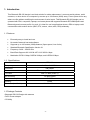
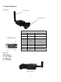
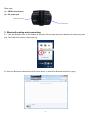
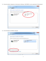
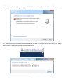
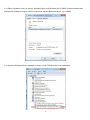
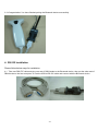
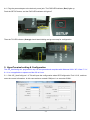
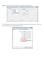
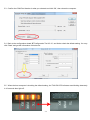
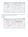
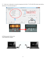
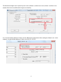
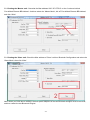
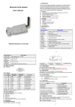
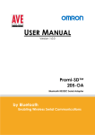
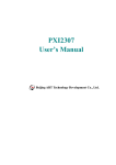
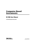
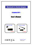
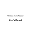
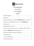
Bluetooth RS-232 Dongle User’s Manual BTS-100 Table of Contents 1. INTRODUCTION.............................................................................................................................. 2 2. PHYSICAL DIAGRAM ..................................................................................................................... 3 3. BLUETOOTH PAIRING AND CONNECTING.................................................................................. 4 4. RS-232 INSTALLATION ................................................................................................................ 10 5. HYPERTERMINAL SETTING & CONFIGURATION ..................................................................... 12 6. REGULATORY COMPLIANCE ..................................................................................................... 19 -1- 1. Introduction This Bluetooth RS-232 dongle is an ideal solution for cable replacement. It connects serial printers, serial scanners, or other device to a computer by remote up to 100 meters (300ft) away. Free to place device any where one like without modifying the environment for wire layout. This Bluetooth RS-232 dongle can be operated with PDA, computers, laptops, and smart phone that supports Bluetooth RFCOMM profile and Bluetooth generic access profile. As such, it is ideal for use in applications where a PDA or laptop could communicate with another device (SBC, RTU, sensor, robot, radio, PBX) wirelessly. 1.1 Features Extremely easy to install and use. No need of external host and software Supports up to 100 meters (300ft) distance (Open space, Line of site). Standard Bluetooth Specification Version 2.1 Frequency 2.400 ~ 2.4835 GHz Baud Rate Supports 9.6/19.2/38.4/57.6/115.2/230.4 kbps Modulation GFSK-1 Mbps, DQPSK-2 Mbps, and 8-DPSK-3 Mbps 1.2 Specifications: Model No. BTS-100 Frequency 2.400 to 2.4835GHz Connector DB-9 Male Standard Bluetooth specification version 2.1 Tx Power Max. 13 dBm (Class 1) Rx Sensitivity -86 dBm typical Power consumption DC 5V Housing Plastic Dimension (L x W x H) 66 x 39 x 20 mm 1.3 Package Contents • Bluetooth RS-232 Dongle with antenna • DC5V Power adaptor • CD Utility -2- 2. Physical Diagram Front view Bluetooth antenna DB9 Male connector Pin Assignment RS-232 pin out Pin No. Definition Signal Name 1 NC --- 2 RXD Receive Data 3 TXD Transmit Data 4 NC --- 5 GND Ground 6 NC --- 7 RTS Request to Send 8 CTS Clear to Send 9 NC --- Side view LED Indicators (1) RX: Orange (2) PWR: Red (3) TX: Orange -3- Rear view (1) SETUP push button (2) DC power jack SETUP push button DC power jack 3. Bluetooth pairing and connecting 3.1 Click the Bluetooth icon on the taskbar of computer OS and plug the power adapter to the device’s power jack. The PWR LED indicator (Red) lights up. 3.2 Use your Bluetooth software and click ‘Add a device’ to search for Bluetooth devices in range. -4- 3.3 Once the device is detected, it will show the ‘Wireless 2.4G RS232’ on the screenshot of ‘Add a device’. 3.4 Click ‘Wireless 2.4G RS232’ and pair. -5- 3.5 Click ‘Enter the device’s pairing code’. 3.6 Enter the pairing code and click ‘Next’. (Default is 1234) -6- 3.7 It may fail to pair and pop up error message if you can not enter pairing code in 60 seconds. Please check your Bluetooth device is working and pair again. 3.8 When the pairing is succeeded, the Bluetooth device will have its COM port number and ready to use. In this case, COM9 & COM10 are distributed to Bluetooth devices. -7- 3.9 When the Bluetooth device is connected successfully, click ‘Close’. 3.10 Click the device icon ‘Wireless 2.4G RS232’ -8- 3.11 Select ‘Hardware’ and you will see ‘Standard Serial over Bluetooth link (COM9)’ in the screenshot that indicates the COM port number used for connection with the Bluetooth device. (Ex. COM9) 3.12 Open the Windows Device manager; it shows a new COM port has been established. -9- 3.13 Congratulation! You have finished pairing the Bluetooth device successfully. 4. RS-232 Installation Please follow below ways for installation. 4.1 Take one DB9 F/F cable and plug one end of DB9 female to the Bluetooth device, then put the other end of DB9 female on the host computer. Or use the USB to RS-232 cable and connect with the Bluetooth device. -10- 4.2 To further check if the COM port was successfully installed; go to Windows Device Manager where the COM port should be listed under ‘Ports (COM & LPT)’. (Ex. COM1 or COM14) 4.3 Install programmer ‘AP_UartConfig.exe’. -11- 4.4 Plug the power adapter to the device’s power jack. The PWR LED indicator (Red) lights up. Push the SETUP button, and the PWR LED indicator will light off. Then the TX LED indicator (Orange) should start blinking and go next step for configuration. 5. HyperTerminal setting & Configuration The ‘AP_UartConfig.exe’ programmer only can be operated and compliant with Windows 2000 / XP / Vista / 7 / 8 / 8.1. It is not applicable to operate on Mac OS or Linux. 5.1 Click ‘AP_UartConfig.exe’ This will open the configuration wizard ‘BTConfiguration Tool V2.10’, and then enter the correct information. In this case we have created COM port 1 so we select COM1. -12- Caution: The COM port only can be selected up to COM9 due to configuration limit. 5.2 If the Bluetooth device does not list in COM1~COM9 from the Windows Device manager, you may click ‘Advanced’ of Port Settings to select applicable COM port. -13- 5.3 Confirm the COM Port Number is what you selected and click ‘OK’, then reboot the computer. 5.4 Back to the configuration wizard ‘BTConfiguration Tool V2.10’, and further check the default setting. You may click ‘Read’ and get the information of this device. 5.5 When the host computer is checking the default setting, the TX & RX LED indicators start blinking alternately in 10 seconds then light off. -14- 5.6 Complete your setting baud rate and Bluetooth Configuration as below. The default password is 1234. Or you may apply changes to any desired settings on Bluetooth device. (1) UART Format (2) Device Name (3) Password -15- 5.7 Confirm your configuration or accept the changes and click ‘Write’. The TX & RX LED indicators start blinking alternately in 3~5 seconds and light off. 5.8 Pairing master & slave units Typical application diagram -16- Two Bluetooth dongles can be paired by one is set as ‘Master’, another one is set as ‘Slave’. And then it can transfer data thru the two Bluetooth dongles successfully. 5.8.1 Check the Mac address of ‘Slave’ unit thru Bluetooth Configuration before setting the ‘Master’ unit. In this example, we get the Mac address of ‘Slave’ unit 001C.97.1FF61C. -17- 5.8.2 Setting the ‘Master’ unit: Overwrite the Mac address 001C.97.1FF61C on the 3 columns behind ‘Pre-defined Remote BD Address’. And then select the ‘Master Mode’; tick off ‘Pre-defined Remote BD Address’ and click ‘Write’. 5.8.3 Setting the ‘Slave’ unit: Check the Mac address of ‘Slave’ unit thru Bluetooth Configuration and select the ‘Slave Mode’; then click ‘Write’. Note: When you finish above settings, the both power adapters of the two Bluetooth dongles must be removed, and then restart the two Bluetooth dongles. -18- 6. Regulatory Compliance Disclaimer Information in this document is subject to change without notice. The manufacturer does not make any representations or warranties (implied or otherwise) regarding the accuracy and completeness of this document and shall in no event be liable for any loss of profit or any other commercial damage, including but not limited to special, incidental, consequential, or other damages. No part of this document may be reproduced or transmitted in any form by any means, electronic or mechanical, including photocopying, recording or information recording and retrieval systems without the express written permission of the manufacturer. All brand names and product names used in this document are trademarks, or registered trademarks of their respective holders. CE Safety Statement This equipment complies with the requirements relating to Electromagnetic Compatibility Standards EN55022/EN55024 and the further Standards cited therein. It must be used with shielded cables only. It has been manufactured under the scope of RoHS compliance. FCC Compliance Statement This equipment generates and uses radio frequency and may cause interference to radio and television reception if not installed and used properly. This equipment has been tested and found to comply with the limits of a Class B digital device, pursuant to part 15 of the FCC Rules. These limits are designed to provide reasonable protection against harmful interference in a residential installation. You are cautioned that changes or modification not expressly approved by the party responsible for compliance could void your authority to operate the equipment. This device complies with part 15 of the FCC Rules. Operation is subject to the following two conditions: (1) This device may not cause harmful interference, and (2) This device must accept any interference received, including interference that may cause undesired operation RF Exposure Statement The equipment complies with FCC RF radiation exposure limits set forth for an uncontrolled environment. This device and its antenna must not be co-located or operation in conjunction with any other antenna or transmitter. WEEE (Waste of Electrical and Electronic Equipment), Recycling of Electronic Products In 2006 the European Union introduced regulations (WEEE) for the collection and recycling of all waste electrical and electronic equipment. It is no longer allowable to simply throw away electrical and electronic equipment. Instead, these products must enter the recycling process. Each individual EU member state has implemented the WEEE regulations into national law in slightly different ways. Please follow your national law when you want to dispose or any electrical or electronic products. More details can be obtained from your national WEEE recycling agency. -19-