1
Primary Switch Mode Rectifier
PSS30
User manual
Page 10 (28)
5.2 Electrical function description
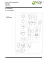
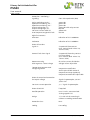
Rectifiers of type PSS consist of following main parts:
1.
2.
3.
4.
5.
6.
7.
8.
9.
10.
Line filter to reduce the high-frequency transients produced by the device as well as damping
the transients and noise voltage which are superimposed on the mains.
Mains rectifier with switched step-up-converter (operation frequency 100 kHz) to transform the
input voltage in a pre-regulated DC voltage of approx. 380V and to control the waveform of the
input current (sinusoidal) as well as to control the power factor (>0.99). An additional function is
the limitation of inrush current.
Transistor bridge to transform the 380VDC to a pulse width modulated AC voltage with a frequency of 100KHz.
HF transformer for the decoupling of the primary and secondary side and adaptation of the
voltage level to the secondary side.
Rectifier diodes
LC filter to reduce the voltage ripple at rectifier output.
Output filter for RFI suppression and to reduce the noise level on DC line.
Internal power supply to supply the primary and secondary control units with potential separation.
Controlled system, opto-decoupled.
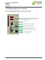
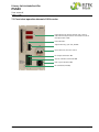
Adjustment panel for adjustment of output parameters, signals and measurement instruments.
5.2.1 Electrical insulation
Due to the construction principle of the module (module parts) and separated wiring of mains input and
DC output, the PSS meets the following standards:
•
•
Devices with Vo ≤ 60VDC protection against dangerous body currents through low voltage with
safe electrical decoupling according to EN 60950 and VDE 0100.
Devices with Vo > 60VDC saved electrical decoupling to Vo = 220VDC according to EN 60950 and
VDE 0160.
5.2.2 Input
The input is protected by 2-pole circuit breaker. This circuit breaker is also used as on/off-switch.
The MCB is -seen from the mains input side- connected ahead of the input filter. An additional internal
fuse is used to protect the controller. The rectifier has a current limitation which limits the inrush current to the level of the nominal input current.
5.2.3 Output
The output line is an IV-line according to DIN 41772 /DIN 41773. Active current sharing mode or decreased charge line (-1% at 100% Inom) is possible. Serially the decreased charge line is factory preset.
The output is sustained short circuit proof (constant current control).
It is possible to use three different output voltages:
1. Voltage for trickle charge
2. Boost charge
3. Battery test
The output voltage for trickle charge is standard set.
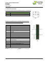
For the use of “Boost charge” or “Battery test”, the pins of the signal connectors are to be connected as
described in section 7.3 “Electrical connectors”.
Eltek Deutschland GmbH ©2011
Eltek_UM_PSS30_E_R2.0