1
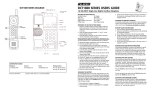
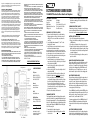
the public is 1.6 watts/kg (W/kg) averaged over one gram of tissue. The standard
incorporates a substantial margin of safety to give additional protection for the
public and to account for any variations in.
INDUSTRY OF CANADA REQUIREMENTS
NOTICE: The Industry Canada label identifies certified equipment. This certification
means that the equipment meets certain telecommunications network protective
operational and safety requirements as prescribed in the appropriate Terminal
Equipment Technical Requirements documents. The department does not guarantee the equipment will operate to the users satisfaction. Before installing this
equipment, users should ensure that it is permissible to be connected to the
facilities of the local telecommunications company. The equipment must also be
installed using an acceptable method of connection. The customer should be
aware that compliance with the above conditions may not prevent degradation of
service in some situations. Repairs to certified equipment should be coordinated by
a representative designated by the supplier. Any repairs or alterations made by the
user to this equipment, or equipment malfunctions, may give the telecommunications company cause to request the user to disconnect the equipment. Users
should ensure for their own protection that the electrical ground connections of
the power utility, telephone lines, and internal metallic water pipe systems, if
present, are connected together. This precaution may be particularly important in
rural areas.
Caution: Users should not attempt to make such connections themselves, but should
contact the appropriate electric inspection authority or electrician, as appropriate.
The Ringer Equivalence Number (REN) of this device is 0.7B.
Notice: The Ringer Equivalence Number (REN) assigned to each terminal device
provides an indication of the maximum number of terminals allowed to be connected to a telephone interface. The termination on an interface may consist of any
combination of devices subject only to the requirement that the sum of the Ringer
Equivalence Numbers of all the devices does not exceed 5. This telephone connects
to the telephone network under the connecting arrangement code CA11A.
IMPORTANT SAFETY INSTRUCTIONS
WHEN USING YOUR TELEPHONE EQUIPMENT, BASIC SAFETY PRECAUTIONS SHOULD
ALWAYS BE FOLLOWED TO REDUCE THE RISK OF FIRE, ELECTRIC SHOCK AND INJURY
TO PERSONS, INCLUDING THE FOLLOWING:
1. READ AND UNDERSTAND ALL INSTRUCTIONS.
2. FOLLOW ALL WARNINGS AND INSTRUCTIONS MARKED ON THE PRODUCT.
3. UNPLUG THE PRODUCT FROM THE WALL OUTLET BEFORE CLEANING. DO NOT
USE LIQUID CLEANER OR AEROSOL CLEANERS. USE A DAMP CLOTH FOR CLEANING.
4. DO NOT USE THIS PRODUCT NEAR WATER, FOR EXAMPLE, NEAR A BATHTUB,
WASH BOWL, KITCHEN SINK OR LAUNDRY TUB, IN A WET BASEMENT, OR NEAR A
SWIMMING POOL.
5. DO NOT PLACE THIS PRODUCT ON AN UNSTABLE CART, STAND OR TABLE. THE
PRODUCT MAY FALL, CAUSING SERIOUS DAMAGE TO THE PRODUCT.
6. SLOTS AND OPENINGS IN THE CABINET AND THE BACK OF BOTTOM ARE PROVIDED FOR VENTILATION, TO PROTECT IT FROM OVERHEATING. THESE OPENINGS
MUST NOT BE BLOCKED OR COVERED. THE OPENINGS SHOULD NEVER BE
BLOCKED BY PLACING THE PRODUCT ON THE BED, SOFA, RUG OR ANY OTHER
SIMILAR SURFACE. THIS PRODUCT SHOULD NEVER BE PLACED NEAR OR OVER A
RADIATOR OR HEAT REGISTER. THIS PRODUCT SHOULD NOT BE PLACED IN A
BUILT-IN INSTALLATION UNLESS PROPER VENTILATION IS PROVIDED.
7. NEVER PUSH OBJECTS OF ANY KIND INTO THIS PRODUCT THROUGH CABINET
SLOTS AS THEY MAY TOUCH DANGEROUS VOLTAGE POINTS OR SHORT OUT
PARTS THAT COULD RESULT IN A RISK OF FIRE OR ELECTRIC SHOCK. NEVER SPILL
LIQUID OF ANY KIND ON THE PRODUCT.
8. TO REDUCE THE RISK OF ELECTRIC SHOCK DO NOT DISASSEMBLE THIS PRODUCT. BUT TAKE IT TO A QUALIFIED SERVICE FACILITY IF
SERVICE OR REPAIR WORK IS REQUIRED. OPENING OR REMOVING COVERS MAY
EXPOSE YOU TO DANGEROUS VOLTAGES OR OTHER RISKS. INCORRECT REASSEMBLY CAN CAUSE ELECTRIC SHOCK WHEN THE APPLIANCE IS SUBSEQUENTLY
USED.
9. UNPLUG THIS PRODUCT FROM THE WALL OUTLET AND REFER
SERVICING TO QUALIFIED SERVICE PERSONNEL UNDER THE FOLLOWING CONDITIONS:
- WHEN THE POWER SUPPLY CORD OR PLUG IS DAMAGED OR FRAYED.
- IF LIQUID HAS BEEN SPILLED INTO THE PRODUCT.
- IF THE PRODUCT HAS BEEN EXPOSED TO RAIN OR WATER.
- IF THE PRODUCT DOES NOT OPERATE NORMALLY BY FOLLOWING THE OPERATING INSTRUCTIONS. ADJUST ONLY THOSE CONTROLS THAT ARE COVERED BY THE
OPERATING INSTRUCTIONS, AS IMPROPER ADJUSTMENT OF OTHER CONTROLS
MAY RESULT IN DAMAGE, AND MAY REQUIRE EXTENSIVE WORK BY A QUALIFIED
TECHNICIAN TO
RESTORE THE PRODUCT TO NORMAL OPERATION.
- IF THE PRODUCT HAS BEEN DROPPED OR THE CABINET HAS BEEN DAMAGED.
- IF THE PRODUCT EXHIBIT A DISTINCT CHANGE IN PERFORMANCE.
10. AVOID USING A TELEPHONE (OTHER THAN A CORDLESS TYPE)
DURING AN ELECTRICAL STORM. THERE MAY BE A REMOTE RISK OF
ELECTRIC SHOCK FROM LIGHTNING.
11. DO NOT USE THE TELEPHONE TO REPORT A GAS LEAK IN THE
VICINITY OF THE LEAK.
PLEASE SAVE THESE INSTRUCTIONS
CONTACTING TELEDEX
Telephone
Main: 1.408.363.3100
Toll-Free 1.800.794.8353
Fax: 1.408-363.3136
Internet
www.teledex.com
store.teledex.com
Email
[email protected]
Mailing Address
6311 San Ignacio Avenue
San Jose, CA 95119 USA
DCT2900 SERIES DIAGRAM
Part Number 600-0480-67
Copyright © 2006 Teledex LLC.
ALL RIGHTS RESERVED.
DCT2900 SERIES USERS GUIDE
1.9 GHz DECT Two-Line Cordless Guestroom Telephone
INCLUDED IN YOUR PACKAGE
Cordless Handset
AC Adapter
Base Unit
User Guide
NiMH Battery
10-foot, 4-wire RJ-11 Line Cord
Rubber Battery Screw Cover
15-foot, 8-wire RJ-45 Cable
Phillips Screw
Clear Plastic Overlay
PREPARING TO USE THE DCT2900 SERIES
1. Prepare to install the battery into the cordless handset by
firmly pressing down on the top of the battery cover and
sliding it off. If cover is secured with a screw, remove the
screw first.
2. Locate the lightly embossed numbers “1” and “2” on the
battery’s plastic connector.
3. Insert the battery connector into the handset’s connector
with the embossed numbers facing up.
Note: The handset may “beep” when the battery is connected. This is not
an indication that the telephone is ready to use. To obtain optimal performance of the telephone, be sure to charge the battery for 15 to 20 hours.
4. Replace the battery compartment cover and retaining screw.
5. Insert the provided rubber screw cover.
6. Turn the telephone base so the back panel is facing you.
Insert either end of the RJ-45 cable into the jack on the back
of the telephone labeled LINE.
7. Insert the other end of the cable into the jack on the AC
adapter labeled PHONE.
8. Insert one end of the RJ-11 line cord into the jack on the AC
adapter labeled LINE.
9. Insert the other end of this line cord into a telephone jack.
10. Plug the AC adapter into an unswitched electrical outlet.
11. Once your telephone is connected, remove the plastic
overlay and place the paper faceplate over the keys. Replace
the plastic overlay by hooking the tabs on the overlay into
the recessed slots located on both sides. The overlay is
easiest to insert when the left or right side tabs are inserted
first, and the middle of the overlay is slightly bowed to allow
for insertion of the other tabs.
12. Place the cordless handset on the base unit.
CHARGING THE BATTERY
The rechargeable battery must be fully charged before using the
phone for the first time. It is recommended that that battery pack
be charged for approximately 15 to 20 hours, without interruption,
before use. To charge the battery, place the handset, keypad down,
in the base unit. Make sure the CHARGE LED on the base lights.
If the LED does not light:
1. Ensure that the AC adapter is plugged in.
2. Ensure that the AC adapter is not plugged into a switched
electrical outlet.
3. Ensure that the handset charging contacts at the bottom of
the handset are making good contact with the base unit’s
charging contacts.
CLEANING THE BATTERY CONTACTS
To maintain a good charge, it is important to clean all charging
contacts on the handset and base unit. Use a pencil eraser or
other contact cleaner. Do not use any liquids or solvents.
BATTERY SAFETY INSTRUCTIONS
1. Use only Teledex-approved battery replacements.
2. Dispose of used batteries according to local codes pertaining
to NiMH batteries.
3. Do not dispose of batteries in fire, as they may explode
4. Charge the telephone's batteries only while in the telephone
handset, and only by using the telephone base unit to charge.
Do not attempt to remove the batteries and charge them in
a separate charging unit.
5. Do not short-circuit the battery pack, as this may cause it to
explode or catch fire.
HANDSET/BASE REGISTRATION PROCEDURE
This procedure establishes an exclusive link between a specific
handset and base, thereby allowing no other access to this
specific base. To accomplish this procedure, place the handset
on the base in the charging position. The LINE indicator will
blink while the process is occuring. This process occurs each
time the handset is placed on the base in the charging cradle.
ADJUSTING THE RING VOLUME
The up and down volume keys will adjust the ringer volume of
the telephone. Additionally, the DCT2900 series telephone has
an optional “courtesy” ring mode, wherein the ring volume
begins at the lowest setting, then automatically rings louder
with each successive ring during an incoming call. To select the
courtesy ring mode, follow these steps:
Press the FLASH key; then the 4 key; then the STORE key; then
press the number on the keypad that corresponds to the line for
which you wish to change to courtesy ring mode, i.e; press the
number 1 for line 1, and the number 2 for line 2.
To return to regular ring mode: Press the FLASH key; then the 1
key; then the STORE key; then the number on the keypad that
corresponds to the line for which you wish to change regular ring
mode.
ADJUSTING SPEAKERPHONE VOLUME
The speakerphone has eight (8) levels. To adjust speakerphone
volume, locate the volume up/down keys, located on the front
surface of the phone below the keypad. With the speaker active,
press the “down” arrow key to decrease the volume level, and
press the “up” arrow key to increase it.
ADJUSTING HANDSET RECEIVE VOLUME
The handset has eight (8) volume levels. To adjust the handset
volume, locate the volume up/down keys, located on the
handset, below the “#” key. Pressing the “minus” (-) key will
decrease the volume level, while pressing the “plus” (+) key
will increase it.
AUTO DIAL KEYS
The DCT2900 series has either five (5) or ten (10) programmable
guest service (auto dial) keys, depending on the model you own.
These keys can be programmed to automatically dial telephone
numbers, or to activate telephone system features. To program the
auto dial keys (programming can only be done from base unit):
1. With the phone “on hook” (inactive) and the faceplate
removed, press the recessed STORE key (see diagram).
2. Enter the desired telephone number (up to 15 digits in
length) to be stored. To enter a “pause” in the number
string, press the REDIAL key as necessary.
3. Press the STORE key again.
4. Press the auto dial key where the number is to be stored.
Programming is now completed for that auto dial key.
To program additional keys, repeat this process.
RECEIVING A CALL
An audible ring and flickering red LED indicate an incoming call.
To answer the call using the handset while it is not on the base:
1. Pick up the handset.
2. Press the line key for the ringing line. The handset will go
“off-hook” answering the ringing line.
3. To end the call, place the handset in the base unit cradle, or
press the lit line key on the handset.
To answer the call using the handset while it is resting on the base:
1. Pick up the handset from the base. The phone will
automatically connect to the correct, ringing line.
2. To end the call, replace the handset in the base unit cradle,
or press the lit line key on the handset.
To answer the call using the speakerphone:
1. Press the line key for the ringing line. The speakerphone will
go “off-hook”, answering the ringing line.
2. Or, press the SPKR key. The phone will automatically select
the correct, ringing line.
3. To end the call, press the SPKR key again.
PLACING A CALL
Using the handset:
1. Pick up the handset and select either line 1 or line 2. Listen
for dial tone and dial the desired number.
2. After the call is complete, press the key for the selected line
again to end the call.
Using the speakerphone:
1. Press key for either line 1 or line 2, or press SPKR.
2. Listen for dial tone, and dial the desired number, or press an
auto dial key to dial a preprogrammed number.
3. After the call is complete, press the SPKR key to end call.
REDIAL
The DCT2900 series can automatically redial the last number
dialed. On the handset, press the REDIAL key to redial the last
number.
CONFERENCE
The CONF key allows for three-way conversations. Depending
on the situation, you may initiate a conference call using one of
these methods:
User initiates two calls:
1. Place call to first party, then place them on hold by
pressing the HOLD key.
2. Using the second line, place call to second party.
3. Once that party is on the line, press CONF to join the first
caller with the second party and yourself.
User initiates one call:
1. After receiving a call from first party, place them on hold
as above.
2. Using the second line, place call to second party.
3. Once that party is on the line, press CONF to join the first
caller with the second party and yourself.
User includes two callers:
1. After receiving a call from first party, place them on hold
as above.
2. After receiving call from second party, press CONF to join
the first party with the second party and yourself.
To terminate a conference call, pressing a line key will maintain
the connection with that line, while dropping the other line. To
terminate the call entirely, press either the CONF key or SPKR key
to disconnect both parties.
USING THE HOLD KEY
The HOLD key places the call on hold locally at the cordless
telephone.
To place a call on hold:
1. With a call active, press the red HOLD key on either the
handset or base unit.
2. The red line LED will flash, indicating the call is on hold.
3. If a conference call is active, pressing HOLD will place all
connections on hold.
To remove a call from hold:
1. Press the line key of the call on hold. This will remove the
call from hold, making the call active again.
2. The red line LED will return to steady illumination, indicating
the line is active.
3. During a conference call, to remove both lines from hold,
press the CONF key.
To change phones after placing a call on hold:
1. Place the call on hold as above.
2. Pick up the call at another telephone that is on the same
line. The telephone will activate the line and remove the hold
at the original telephone.
TO MUTE THE SPEAKERPHONE
1. Press the MUTE key on the base unit. The red LED above
the MUTE key will illuminate. The party on the other end
will not be able to hear you when the MUTE LED is lit.
2. Press the MUTE key again to turn off the mute feature.
The MUTE LED will go out.
CONVERTING FROM DESK TO WALL MOUNT
The DCT2900 series can be adapted for wall mounting applications. The conversion is easiest to make when the handset and
cords are not connected.
1. Located on the handset cradle, above the speaker grill, is the
wall/desk mount clip. Remove this clip by firmly pushing it
upward towards the top of the phone.
2. Flip the clip over (top to bottom) so that the protruding edge is
towards the top of the phone and replace it in its slot. This edge
will hold the handset when the phone is mounted on the wall.
3. Turn the telephone over so the bottom is up, facing you.
Place it on a non-abrasive surface to prevent scratching.
4. Locate and remove the mounting bracket. Firmly push back
and pull up to remove two of the four retaining tabs.
5. Rotate the mounting bracket 180º degrees clockwise, so that
the mounting eyelet on the bracket is facing in the same
direction as the other mounting eyelet located on the
bottom of the telephone.
6. Insert the top two retaining tabs of the mounting brackets
into the mounting bracket slots (located near the middle of
the telephone). Then firmly push down to insert the retaining
tabs on the opposite side of the mounting bracket.
7. Connect a 15-foot RJ-45 cord into the LINE jack on the back
of the phone.
8. Turn the telephone over, and slide the telephone down onto
the mounting posts of the wall bracket. Ensure that both
eyelets line up with the mounting posts.
REQUIREMENTS OF PART 68 - FCC RULES
This device has been granted a registration number by the Federal Communications
Commission, under Part 68 rules and regulations for direct connection to the telephone lines. In order to comply with these FCC rules, the following instructions must
be carefully read and applicable portions followed completely:
1. Direct connection to the telephone lines may be made only through the standard
modular cord furnished, to the utility installed jack. No connection may be made to
party or coin phone lines. On the bottom of the phone is a label that contains among
other information, the FCC Registration Number and the Ringer Equivalence number
(REN) for this equipment. If requested this information must be provided to the telephone company. The USOC Jack for this equipment is RJ11C.
2. The telephone company, under certain circumstances, may temporarily discontinue
and make changes in facilities and services which may affect the operation of the
users' equipment: however, the user shall be given adequate notice in writing to
allow the user to maintain uninterrupted service.
3. In certain circumstances, it may be necessary for the telephone company to request
information from you concerning the equipment which you have connected to your
telephone line. Upon request of the telephone
company, provide the FCC registration number and the ringer equivalence number of
the equipment which is connected to your line; this information will be found on the
device.
4. If any of your telephone equipment is not operating properly, you should immediately remove it from the telephone line. It may cause harm to the telephone network.
5. If the telephone company notes a problem, they may temporarily
discontinue service. When practical, they will notify you in advance
disconnection. If advance notice is not feasible, the telephone company must;
promptly notify you of such temporary discontinuance; afford the opportunity to correct the condition; inform you of your rights to bring a complaint to the FCC under
their rules.
6. Repairs to the device may be made only by the manufacturer or an authorized service agency. This applies at any time during and after
warranty. If unauthorized repair is performed, registration, connection to the telephone
lines and remainder of warranty period all become null and void.
7. This equipment is hearing aid compatible.
8. This telephone must be connected behind a PBX.
REQUIREMENTS OF PART 15 - FCC RULES
Statement according to FCC part 15.105: NOTE: This equipment has been tested
and found to comply with the limits for a Class B digital device, pursuant to
Part 15 of the FCC Rules. These limits are designed to provide reasonable
protection against harmful interference in a residential installation. This
equipment generates, uses and can radiate radio frequency energy and, if not
installed and used in accordance with the instructions, may cause harmful
interference to radio communications. However, there is no guarantee that
interference will not occur in a particular installation. If this equipment does
cause harmful interference to radio or television reception, which can be
determined by turning the equipment off and on, the user is encouraged to try
to correct the interference by one or more of the following measures: Reorient
or relocate the receiving antenna; Increase the separation between the
equipment and receiver; Connect the equipment into an outlet on a circuit
different from that to which the receiver is connected. Consult the dealer or
an experienced radio/TV technician for help.
Statement according to FCC part 15.21: Modifications not expressly approved
by this company could void the user’s authority to operate the equipment.
RF Exposure (Handset) (DECT): This device and its antenna must not be
co-located or operating in conjunction with any other antenna or transmitter.
RF Exposure mobile (Base) (DECT): The internal/external antennas used for this
mobile transmitter must provide a separation distance of at least 20 cm from
all persons and must not be co-located or operating in conjunction with any
other antenna or transmitter.
SAR: Tests for SAR are conducted using standard operating positions specified
by the FCC with the UPCS handset transmitting at its highest certified power
level in all tested frequency bands. Although the SAR is determined at the highest certified power level, the actual SAR level of the UPCS handset while operation can be well below the maximum value. In general, the closer you are to a
wireless base station antenna, the lower the power output. Before a Handset
model is available for sale to the public, it must be tested and certified to the
FCC that it does not exceed the limit established by the government-adopted
requirement for safe exposure. The tests are performed in positions and locations at the ear as required by the FCC for each model. While there may be differences between the SAR levels of various UPCS handsets and at various positions, they all meet the government requirement for safe exposure.
Health and Safety Information FCC: Exposure to Radio Frequency (RF) Signals.
Your wireless handset is a radio transmitter and receiver. It is designed and
manufactured not to exceed the emission limits for exposure to radio frequency
(RF) energy set by the Federal Communications Commission of the U.S.
Government. These limits are part of comprehensive guidelines and establish
permitted levels of RF energy for the general population. The guidelines are
based on the safety standards previously set by both U.S. and international
standards bodies: This EUT has been shown to be capable of compliance for
localized specific absorption rate > (SAR) for uncontrolled environment/general
population exposure limits specified in ANSI/IEEE> Std. C95.1-1992 and had
been tested in accordance with the measurement procedures specified in
FCC/OET Bulletin 65 Supplement C (2001) and IEEE Std. 1528-2003 December
2003).The standards include a substantial safety margin designed to assure the
safety of all persons, regardless of age and health. The exposure standard for
wireless UPCS handset employs a unit of measurement known as the Specific
Absorption Rate, or SAR. The SAR limit set by the FCC and IC Canada is
1.6W/kg *. * In the U.S. and Canada, the SAR limit for mobile phones used by