1
/13%ffi
Information & Instruction Manual for
American Beauty@ Resistance Soldering Equipment
Solutions for your difficult soldering needs.
When it comes to soldering equiprnen! American Beauty@ has been
a trusted name in industry forwell over one hundred years.
Information & Instruction Manual for
Arnerican Beauty@ Resistance Soldering Equipment
ffi
Manufacturers of American Beauty@
Quality Soldering Tools
Table of Contents
Section Title
Page
1.0 lntroduction
2.0 Description
2.1 The Science of Electricity
3.0 Safety-General
3.1 Safety-Heat Related
3.2 Safety-Ventilation Related
3.3 Safety- Electrical Current
4.0 Resistance Soldering Equipment Uses
5.0 Basic System Configuration
5.1 Ghoosing the Correct Handpiece
5.2 Handpiece Recommendations
5.3 Choosing the Gorrect Power Unit
5.4 Power Unit Recommendations
6.0 System Set-up nstructions
7.0 Developing Your Soldering Process
7.1 Determining Appropriate Pgwer Levels
f
7.2
8.0
3
3
4
5
'|
5
5
5
6
6
6
7
8
I
9
9
10
Maximum Operating Parameters
10
Troubleshooting Your Equipment
11
+EF
Intbrmatron & Instruction Manual for
Ilanufacturers of .\ms:-: l:'
Quality Soldeine l:.: -.
:
1.0 Introdueion
Ifyou have only recently become aware ofResistance Soldering'Equipment and its various
tind it interesting to note that this is actually not a new concept. The American Beautf
i
uses you ma)'
line ofResistance
Soldering and Thermal Wirestripping equipment has been manufactured and available for over fifty years.
The entire line of American Beaun! soldering equipment'is developed and manufactured exclusively by
Assembly Technologies Intemational Inc.* located here in suburban Detroit. Michigan.
As the manufacturer ofthe largest assortment ofpower units, handpieces and related accessories available
anywhere, we pride ourselves in being the worlds leader in the design and development ofresistance based
soldering equipment. Each item that we manufacture is being continuously evaluated and improved upon so
that we may offer you the highest performance along with the safest, most efficient. user tiiendll equipmenr
available for any Resistance Soldering or Thermal Wirestripping applications that.!'ou ma1 t'e ;..ns:oe::;rg
All American Beaut-v'' products are manufactured using the highest quality of materials thar.ue:re:l:bie
and are assembled with -sreat care so thel r'ill consistentlv conform to our exacting qualiq spe;:r:;ail.'ns
This is why we are able to offer our Industr_r'Best -Three Year Warranty Policy" $hich ma1 ie rlesei
any time on our Web-Site at uuv'.americanbeauqtools.com under the Support heading.
We are certain that with proper care and maintenance, all of the American Beaut-v! Resistan.'e Stldenng
and Thermal Wirestripping equipment.vou have purchased will provide a long and reliable sen ice lit'e.
This manual has been developed to address manv ofthe specific questions and concems llru ma] have that
relate to the Principles of Resistance Soldering, Thermal Wirestripping and other applicarrlins r\here the use
ofan intense localized heat may be beneficial. We will cover general operating procedures. insrructions and
helpful guidelines as well as some very basic safet_v issues and concems that ma)'be a-.s..ciared uith the use
of this type of equipment. You will also find helpful information within the Support 3rii rlltrur \\-eb-Site.
We are confidant that you rvill find the intbrmation that is being presented uirhin thrs manual to be helptul
and informative, horvever if vou har e questions that are beyond the scope of s hat this manual covers please
take a moment to call us toll tiee ar I 80tl ) 550-25 10.
Yoa will frnd that we arc alw'u;-s happy to help provide "Solufions
for
Your Dilficuh Soldning .\eedr ".
2,0 Description
All soldering applications require the introduction ofenough heatto activate the t'lux and t'lou the solder.
Whenever tools that are being used ttr pertbrm a soldering application take too long to achieve the required
process temperature, tle potential tirr thermal damage exists. Resistance Soldering Equipment gives a user
the ability to manufacture an intense level of heat that can be regulated and localized rvithin the intended
solder joint in a more efficient manner lhan most other available methods. This means a faster soldering
process and less time for dissipative heat to cause any thermal damage to the components that are being
soldered or any materials or components that may be within the immediate area sunounding the intended
solder
joint.
Resistance Soldering is accomplished bl producing a safe (lorv-voltagerhigh-amperage) AC current which
is then passed through special electrc.des (manufactured out ofhigh resistance metal allols or other resistive
materials) to generate an intense level of available heat. A closed loop circuit is required so that the current
can be passed from one resistive electrode directly through the base metals that are being soldered and into
the other electrode back to the po*er unit. An isolated transformer is used so that the current does not stra]
or leak into unwanted areas. but talies the most direct path from one electrode to the other rvhich completes
the circuit that is required to generate the desired heat. The resistance ofthe special electrodes that are used
creates the majoriqv ofthe heat that is being generated. Anl additional resistance rhat exists at the point of
contact and within the base metals that are being soldered will increase the amounl of available heat that can
be generated within the solderjoint. 81'regulating the output voltage olthe resistance soldering power unit
the heat that is generated can be adjusted to the specific level required tbr the soldering application that is
being performed.
ffie
Information & Instruction Manual for
Amertcan Beauty@Resrstance Soldering Equipment
Manufacturers of American Beauty@
Quality Soldering Tools
2.1 The Science of Electricity
Resistance heat can be developed because ofthe three fundamental forces that control all electrical circuitsl
vol tage. amperage, and resistance.
lbltage
Its scientific name is electromotive lorce lvhich is usually represented in formulas with a capital letter ''E".
The electromotive tbrce or electrical pressure that moves an electrical cunent through a conductive material
is measured in units that are called volts. One lolt is equal to the amount ofelectromotive force necessary to
force one ampere ofcurrent to flou through a resistance ofone ohm. Generally a higher voltage means that
more current will flow and a louer voltage means that less cunent will tlos through an electrical circuit.
he used lo measure the amount ofvoltage (electrical pressure)
A voltmetet can
in the circuit
Amperage
The scientific reference is intensitl Lrlcurrent flow usually represented in formulas with a capital letter "I".
The rate at which an electrical cunent u ill l'lorv through a conductive material can be measured in units that
are called amperes. One ampere equals a tlon of6.25 x 1023 electrons (called one coulomb) per second.
Using the water flowing through a pipe analogl to describe the way that current florvs along a conductor,
current rvill flow more readill through a short thick conductor than through a long nanorv conductor.
,4n ammeter can be used to measure the amounl of ct nent that
Although
a greater amount
is
Jlowiilg through a circuit
nill flou-alone a conductor,
also be dependant upon the amount of resistance encountered.
ofvoltage can increase the amount ofcunent that
the actual amount ofcunent that florvs lr
ill
Resistance
Resistance is the property ofa material which resists or opposes the flow ofan electrical cunent through it.
The actual resistance (R) of a material is dependant upon its resistivity (p) which can be different for each
nraterial, along with its physical characteristics tsuch as the materials overall length and cross-sectional
area).
This can generally be shown as R: pLlA, rvhere R is the resistance in Q (ohms). p is the known resistivity
of the conductive material, L is the length ofthe conductor and A the cross sectional area ofthe conductor.
Resistivity (p): is unique to each material being soldered.
Length (L): A greater length increases the amount of resistance and a shorter lengh decreases resistance.
Area (A): A greater area decreases the amount of resisrance and a smaller area increases the resistance.
An ohmmelet
q4
be used to measare the omount of rcsistance that eyists
in a conductive material
Resistance Heat
Resistance heat is the heat that is developed as an electrical cunent is passed through a conductive material
because ofthat conductive material's resistance (or opposirirrn) to the cunent that is being passed through it.
Whenever an electrical cunent (l) flows through a conductive material with resistance (R), electrical energ;is converted to heat at a rate ofpower (P) that may be calculated as P: I? R, where P is the polver measured
in watts, I is the cunent measured in amperes and R is the resistance measured in O lohms).
The heating eflect of resistance is often considered undesirable in the transmission of current tbr most
electrical applications and must be minimized, but it is verl useful tbr intentionally generating electrical
heat tbr a variety of uses, in this case Resistance Soldering. Understanding that some materials have a
higher level ofresistivity than others and that the actual amount ofresistance can be altered by changing the
physical characteristics of the material is an important part ol us creating and utilizing resistance heat tbr
various soldering applications.
+ffiF
\Ianufacturers of .{rne:::a: 3=.-;.
Quality Solder:r:g li: -.
-1.0
Safety-Generol
'
,
.{ll of the American Beautyi
resistance soldering or thermal wirestripping equipment that is manufactured
b."- Assembly Technologies Intemational Inc.* should be operated in complete compliance with all federal.
state and local regulations that exisr pertaining to the varioqs uses for this type of equipment. This includes
actual use, storage, safe handling and disposition ofanv materials, components. tools or other products that
may be used in conjunction rvith this equipment. Consult the manufacturers of the solders, fluxes, cleaning
agents and other products that might be used along rvith this equipment and request a copy oftheir current
Material Safety Data Sheets t\lSDSs.l or other available information, documentation or specific wamings
regarding each of their individual products. It is important to become familiar with all MSDSs. operations
manuals, information and instruction sheets, stickers, labels, inserts and other related material or documents
that are currently (or that become) available regarding our products and any other materials ..r equipment
that may be used in conjunction with them.
3.
I
Safety-Heat Related
As previously stated, all soldering applications will require the introduction of some ier el ..f helt :.. i,e
flux and melt and flou.the solder. It is important to exercise caution $hen rperaring anr
products or equipment that are used to manutacture or generate the required heat. The devekipment of satt
operating practices and proper training procedures rvill help eliminate the possibilir."" of an1 .rc;idental bums
or other potential hazards. All operating personnel must be aware ofthe proper handling pr..cedures for any
combustible or flammable materials that might be required for your specific soldering appiicatierns.
Systems should be tumed offwhenever the) eue not in use or they are going to be lett temporarilv unattended in order to help prevent any accidental actuations.
able to activate the
3.2 Safety-Ventilation
Related
Proper ventilation is a signiticant consideration lor any type ofmanufacturing and pr..cessrng environment.
This fact is especialll'true rrhere there is a potential for smoke, fumes. vapors or other irriranls and airbome
contaminanb that exist or develop. There are a rvide variety of sizes, sr_'-les and rypes .ri r entilatron. exhaust
and air tiltering s) stems availaL,le rr hich have been specifically designed for the remtrr al .rf oft-ensive odors
and potentialll" harmful smoke. fumes trr vapors that may be given offduring variLrus srrldering applications.
Be sure that you have obtained. read and fullv understand all ofthe available documentation regarding the
proper use, storage and sale handline .rf anv materials and equipment that you ma]' be intending to use with
your soldering applications. This should include any requirements for protective cltthing shielding or other
apparatus that may be_speci{igd
3.
3
Safety-Eledrie*l
-C u rr e nt
Resistance Soldering equipment consists ofvarious electrical devices that are intended for use in soldering
applications to help improve the saliq . qualiry and effrciency of many of.vour current soldering processes.
This equipment must be used in ctrmplete compliance with all of the applicable sal'e operating procedures,
local ordinances and other guidelines and regulations that exist for the locations shere thel are being used.
Failure to follow the specific instructirrns. procedures and guidelines can result in the possibilitl ofinjuries
to your operating personnel or damage to equipment which could otherwise have been avoided.
The output that is produced bv all rrfthe American Beauty Resistance Soldering Pelser Lnits is a very safe
low-voltage AC cunent this equipment operates on standard 1 10-120 or 220-2-10 .A.C line voltage. However.
opening the Power Unit enclosure can expose an operator or individual to the possibiliq ofvarious electrical hazards. Any troubleshotrting practices and maintenance procedures that mal be required should be
attempted by qualified personnel onll'.
Information & Instruction Manual for
American Beauty@ Resistance Soldering Equipmenr
4.0
#o
Manufacturers of American Beauty
Quality Soldering Tools
Resistance Soldering Equipment L'ses
Because ofthe abiliqv to very rapidh produce an intense level'ofcontrolled, localized heat. directll'u.her
it is needed tbr soldering .vou rvill t'ind tha aimtrst anv soldering metlod or process that currentll' exists ca
be improved upon uith the use of resistancr sLrldenng equipment. The wide variety of available handpiecr
manuihctured tbr use with various poser unrts ranging ih maximum outputs of 100 to 3000 watts give
_v-o
the abilitl lqr pertbrm a virtuallf intlnite number ol soldering applications that can range from very sma
electronic components all the wav up to 3'- diameter thin wall metal pipes or other tubing that is used in
varietl of plumbine. retiieeration and H\'.{C applications.
$'ith the conectll contigured s)stems )rru rrill aluals be able to produce the higher temperatures that at
required for various hard solders and er en manl of rhe lotv to mid-temperature brazing materials that exis
Resistance soldering equipment is ernen the pert'ect choice tbr applications involving temperature sensitil
components that are either being s..ldered themselves or are located within close proximity to the materia
that are being soldered. For this qpe lf soldering applications it is very important to be able to apply a hig
enough temperature to the correcl iocallon and for the shortest amount of time possible in order to minimiz
the amount of heat that travels as a1 rrrm the solder joint. This is one of the primary reasons for choosin
resistance soldering equipment over sL) manv ofthe other types ofsoldering tools dnd equipment that exis
Some of the other reasons for resistarce scrlderins rue more consistent repeatability and improved qualiq
throughput and effrciencl . .{s 1 our operators gain more experience the number of uses is sure to increase.
Thermal Wirestripping is another npe of application that resistance soldering equipment may be used fo
This is best accomplished bl using one of the manl specially designed handpieces that have been develope
specifically for thermal wirestripping applicatitns along rvith the conect resistance soldering power unit.
Using the cotect equipment
5.0
fot
a4' ptocess grcatb' affects the quality and elficiency level you achieve.
Basic System ConJigaration
When configuring the basic resistance soldering system that will be required for any applicatior
your three primary components will be a handpiece. a power unit and a footswitch. There are a wid
variety of American BeautyD resistance soldering handpieces and several power units available to choos
from along with various accessories rvhich migtrr ais,. be recommended or required for more specialize
applications. It is important to properl] match the handpiece and power unit to the intended solderin
applications when configuring a s-vstem. in order tt be .rble to marimize the full range of benefits that ca
be obtained with the use of resistance soldering equrFment. You should determine the most appropriat
handpiece to use for the application first and then rq.g srll be better able to decide on the power unii th:
will give you the w-idestpossible working range and rersatility. Ifyou are considering using resistanc
soldering equipment for more than one applicatitrn. ) ou rna) find it beneficial to evaluate the requiremenl
of the largest application first. This approach can decre.::e ]our total cost of ownership by purchasing
single power unit to work in conjunction with multiple h.rndpieces.
5.1 Choosing the Correct Handpiece
When you are deciding on the most appropriate handpiece ro use for an application you should consider th
process that is being developed along with the size. shape and tlpe ofthe materials that are being solderec
The handpiece style that is being chosen for a specific apphcarron should allow for proper placement ofth
electrodes to the work based on the accessibility to the srrlder_roint area along with any special horizontal c
vertical orientation of the handpiece that may be required ttr ,'trmibrtably perform the soldering task. Th
electrodes size requirement will help determine the required handpiece size. The electrodes size should b
properly matched to the work requirements, because a grearer area of contact between the electrode an
work surfaces will help to increase the overall efficiencl rri the thermal transfer that will be taking plact
Even though electrodes can be modified in order to maximize rheir effrciency. you should choose the typ
and size that will most appropriately match the intended application prior to these modifications bein
made.
Manufacturers of .{m*cs
Quality Soldering :\
5.2 Handpiece
Recommendations
3eri !
:
,
The handpiece styles that are currently available include single electrode (used rvith a lead for current
return) dual electrode stationary, dual electrode tweezers, dual electrode pliers. dual electrode forks and a
variety of handpieces designed especialll for thermal wire stripping. All of the handpiece styles that are
listed here are available in a varietv of sizes in order to best meet the specific application requirements that
might exist.
Single Electrode Handpieces give -vou the ability to direct the heat to a specific point of contact in the
same manner as you would with a conventional soldering iron but with a much higher thermal capaciry
available. Using a lead for cunent retum will be necessary with the use of this st1{e of handpiece in order
to complete the required current path. The most appropriate handpiece size to choose is directll related tt
the electrode that will work best for the application that is being considered. Choose the ele.'trode :ize ;n ihc
same manner as you would when choosing a soldering iron tip size. Match the electrode diameler l.' :he
area being soldered.
Stationary Dual Electrode Handpieces sere initially developed for the highl."- repetitile sricer:ng of
similar sized terminations (terminal strips. multiple termination buss bars, etc.). The] ma1 be used on
applications similar to those where single electrode handpieces might be considered but the] do not require
the use of a lead for cunent retum to operate properly. The electrode tips are positioned in :r ;lose proximiry'
to one another and will complete the cunent path b)- passing current through the surface ofthe material that
is to be heated. With minor adjustments or modit'ications to the electrodes (bending. grinding. etc.) they can
be positioned in a manner appropriate to the requirements ofthe application that the] are intended fbr.
Tweezer Style Dual Electrode Handpieces will allow you to direct the heat ttr a specific area while
actually holding the component in place during a soldering application. After florving the solder .v-ou can
deactivate the footswitch while continuing to hold the component in place to cool. This helps to eliminate
cold solder joints that might be caused by agitation of the joint while it is cooling. The metal electrodes
being used in these handpieces can be bent to improve the ergonomic teel of rhe handpiece and the
electrode tips can be contoured to custom fit the work surface improving the thermal ransfer tiom the
electrodes into the work.
Pliers St-vle Dual Electrode Handpieces are similar in design to tweezer s4le handpieces but
were
developed for heavier applications and can obtain much higher operating temperatures. These handpieces
incorporate carbon block electrtrdes that allorv you to operate at temperature levels shich could actually
melt the metal allol electrrrdes rhat are used in the tweezer style handpieces. Carbon block electrodes have
increased lrork surtbces and can be contoured to increase the surface contact area of the electrodes to the
work even further. Ths inerea-ied crrntact area will greatly improve the thermal transfer that talies place
during soldering. _ .
Fork Style Dual Electrode Handpieces are similar in design to the largest
heav-v-dutv pliers-stvle
handpieces. These handpieces incLrrporate an entirely different type of adapter and electrode configuration
allowing for an increased level of versatilit-v. Because the electrodes are rods and the adapters can be
swiveled for more specific orientation of the electrode tips to the required surface area of the work many
applications may be performed nith an increased level ofefficiency and control.
Thermal Wirestripping Handpieces have been developed primarily for the purpose of thermally stripping
the insulation from wires to help minimize the hazard of nicking scoring or othenvise damaging the
conductors. These handpieces have closed loop elements which will begin to heat as soon as the power unit
is activated. The output ofthe ptser unit should be adjusted only high enough to allot the elements ofthe
handpiece to reach the temperarure required for melting through the insulation $ ithout buming it. The nvo
basic types ofthermal uirestripping handpieces that are cunently manufactured are the nveezer st-vle and
the V-notch style. The trveezer srlle handpieces are designed for stripping smaller gauge wires and the Vnotch style are designed for stripping the larger gauge wires.
Soller Reflow Tools
are similar in design to the V-notch stvle rvirestripping handpieces and although thel'
maybeusedforwirestrippingthe;-neredevelopedforawidevarietl
olotherapplicationswhichinclude
solder reflow, wax sculpting, lvood buming, trimming plastics. stained glass work and much more.
*ffip
Information & Instruction Manual for
Manufacturers of American Beauty@
QualitY Soldering Tools
American Beauty@ Resistance Soldering Equicment
5.3 Choosingthe Correct Power
L:nit
'
tbr an application the.final decision should be based not
when deciding on the correct po$er unit tcr bt used
for
applicaiion but also the temperatwe that is required
trrat
tor
chosen
naiu..n
ttat
onlv on the handpiece
brazing materials which
various
and
h*d..olders
ib,
is-especiatt',*.
*.a.1trtt
a
to flow and wet properly' You should aSvays consider
require signiticantll- greater f.u.ii oi tt."t rn trider
determined,to be required for the
hive
you
what
than
or,pu,
unuiinUi.
tign.,
u
has
no\\.er unir rhat
continuous
rnis rvitt give 1:uru assurance that the power unit will not require
increase the output
to
ability
the
have
you
that
insure
ivill
also
operation ar irs marimum *rpuir.n.i. ittis
the operators become more proficient with a soldering
oower level arld lower the reiuired clcle times as
is planning ahead and allowing tbr potential
;il'r;il;;;ii-u.
ilil:#
il;r.
iowth
#r=;;;;"J.
ffi#.';;;;i";';."il;;;.fil;.*'ia.'uiion
into larger applications a' the need mal anse'
5.4 Power Unit Recommendations
include infinitely variable-''selectively variable
The variety of power unit lpes thar are ;unentlyavailable
type ofpower unit listed,here is manufactured
specific
each
rhat
r.iil
irnd
i-.*
and multiple output models.
shown below are based upon
recommendations
All
;f.the
t.t.tr.
*tpur
in a va'iety of ma,ximum
appropriate equipment for
most
the
"trituUt.
determine
guide
to
as a basic
broad speculation *o rt outi o-nti: JG.o
your potential requirements'
Infinitely variable Power Lnits incorptrrate a solid
the
state voltage regulating device in order to allow
po$er
hnest level of adjustment to their output
:
This tr-pe of power unit is available tn eilher
rl05A3powerunitsarecapableofproducinguptol00wattsofporverandmaybeusedtosolder
materials and components that do not ex;eed
o
I
3" diameter'
watts of power and may be used to solder
I05Al2 power units are capable of prtducing up to 250
materials and components that do not excsed
I
-1" diameter'
power f nits incorptrare an ergtrr-i8) position tap switch along with an off center
Selectively variable
high'
unrr-erght Oiint.nt output selections at each of the
tapped transform.. r..onOury.-Ciiing th.'por..,
from.
choose
to
selections
furpur
medium and low levels of output po\ir or i-l specitic
ThLst,-peofpowerunitis.availaibineirherll00uanor:\'lrrnximumavailableoutputs'
l0582powerunitsare-capableofproducinguptollt.x-.\\attsofpowerandmaybeusedtosoldermaterials
diameter'
and components that do not exceed 1/2"
l05Clpowerunitsarecapableofproducinguptols0r-r$3nSr]fpowerandmaybeusedtosoldermaterials
and components that do not exceed a 1" diameter'
ilIultiple output Power Units incorporate
an
offcenter npped transformer secondaq to all!l\\
high, medium and low levels ofoutput power'
watt or
This type ofpower unil is available in either 1800
30(10
vdn
t-or either
available outpttts'
'l'L\nnnl
trfpolver and may be used to solder materials
rvatts
1800
to
up
ofproducing
105c2 power units are capable
recommendations.
tubing
Nall
thin
diameter
that do not or..o ttt. 3"
-J.-orripon.no
materials
up to 3000 $atts trf polver and may be used to solder
105D1 power units are capable of producing
recommendations.
rubing
wall
thin
"
Aiu*it.r
f
that do not exceeO
-J.o-,npon.n,,
t.
#
lv{anufacturers of Amer:cg: 3r
Quality Soldering T:.:
r
-.
60
Sy'stem Set-up
Instrudions
.
The first thing to do is fit the three prong 5-15 NEMA plug that is attached to the porver unit cord into rhe
receptacle portion of the piggy-back si1-le plug that is attached to the footswitch cord assembly and then t'ir
the plug portion of the footswitch into anl properl-v grounded 120 VAC outlet. with the power unit at the
lowest setting and tumed on, activate the footsrvitch. The light on the power unit should come on, indicating
that the power unit and footswitch are both functioning. When the footswitch is released the light should go
out as there is no longer anv current being supplied to the power unit. Attach the handpiece connections to
the appropriate taper pin receptacles or threaded posts that are located on the front or top ofthe power unit.
Single electrode style handpieces rill require the use ofan appropriate lead for current return to provide the
required closed circuit in order to achieve proper curent flow and generate heat.
The power units produce a sale low voltage,
altenartng (AC) cufient
so therc is no concern
lot polatil'-
Heavy-Duty handpieces that have been developed tbr the higher power ranges are manutacrur.d *l'i'i -: S"
ring terminals fbr a more perrnanent and mechanical connection to the threaded posts thar arc imFi.)ed L1n
the higher output pol\'er unis. This minimizes the electrical resistance that may exist at this itrn.n€Jritifl ud
helps eliminate the possibiliS ofthe handpiece connection loosening over time. Handpieces rhar nave been
developed for the lower po\\er ranges are manufachrred with specially designed taper pin rerrnlnations for
quick connection to the custom receptacles that are employed on the lower output pouer unirs. This gives
users the ability to quickly change back and tbnh between the variety of handpieces thar ma) be required
for a specific process. For connection you simpll push the taper pin into the receptacle tuming clockwise
until it is snug.
Converting your Taper Pin connectors to Ring Terminals:
When a process is developed involving the lorver output power units, uhich does nert require changing
handpieces the mechanical connection as mentioned above can be implemented. Thrs is done bl removing
the taper pins from the handpiece and anaching l14" ring terminals in their place. The handpiece can then
be attached to the pouer unit uith the use of3/-1" length l/4-20 brass bolts. because the receptacles are
alread) tapped to accept the 1 J-10 bolts.
7.0 Developing I'our Soldering Process
With the equipment pr.rperll selup as described above it is time to develop lour resistance soldering
process. Devellrptng the srlJenng prlrcess using resistance soldering equipment is quite simple and rvill be
ver) eas) to mliter. i'n.. \.'u rulh understand the basic principles ofelectriciq that are involved in the
development r.ircts.ten;rlrai lJtrs manual should answer the majoritl of lour questions and get.vou on
the right track.
All ofthe American Beaun r
resistance soldering power units have a specialll developed transformer that
converts your standard I l0-110 \'.{C input line voltage into a completell safe (lo$ voltage,rhigh amperage)
AC electrical cunent. When this sate. l!r$' voltage current gets passed through a resistive material an intense
amount of heat can be developed u ithin the immediate area of resistance. This immediate area of resistance
exists within the intended solderjoint area ofthe base materials located benveen rhe tips ofthe electrodes.
Resistive heat will be developed because of the resistance that an electrical current encounters when being
passed through the electrodes and the base metals. A closed circuit is required in order to maintain the path
for proper current flo* . The am.runt of heat produced is determined b;- the output current being supplied b-uthe power unit. It is imponanl tlr determine the output current that is required to produce the correct level of
heat for the process that is beine developed. Your primary goal should be lo establish the shortest dwell
time in which you can comtirnabl)' create good qualitv solder joints. In the beginning this must be
accomplished by trial and error. houever as you become more accustomed to the resistance soldering
equipment you rrill become bener able to predict the required du'ell times and the most efficient output
settings with a far greater level of accuracy and consistency.
Information & Instruction Manual for
American Beauty@ Resistance Soldering Equiprnent
ffip
Manufacturers of American Beauty@
Quality Soldering Tools
In the beginning stages ofyour nel\'process derelopment it is often very beneficial for
-vou to use dummy
components or scrap pieces of similar size and material to the ach-al components that you will be soldering.
This should help you to establish the most elficient porver unit output to be used without causing unwanted
damage to any expensive materials or compLrnents during the initial process development stages.
Whenever a soldering application involves joining togethei pieces ofvastly different sizes, or components
that mav be highl-"" sensitive to thermal damage. ]ou may want to consider pre-tinning the pieces separately
and then joining them together by re-flowing the solder and adding enough new solder to complete the joint.
7.1 Daermining Appropriote Power Levels
Establish a good contact with the base materials (close to the intended solderjoint area) and both electrodes
(or the single electrode and retum hamess clip) and activate the footswitch. Apply solder to thejoint area as
it is heating, then release the tbotssitch once the solder has properly flowed. Because there is no longer any
current being supplied to the handpie.'e. 1ou will be able to hold the components in place while allowing the
solderjoint to cool undisturbed until the solder has finished setting.
Upon completion of the first solder joint l ou should be able to evaluate the results that have been achieved.
Based upon this evaluation 1ou should be able to determine whetier there are any adjustments that might be
recommended or even required to improve the soldering process. You should be especially concemed about
the amount of dwell time thar is required in order to properly flow the solder. Remember that your goal is
to estalrlish the shortest dnell time
solder joint.
in which )'ou can comfortably and efficientlv create a quality
If the output of the power unit is set too high \Lru ian prlrduce dt'ell times so shon that lou will have little
or no measure ofcontrollability. Dtell times that nlie iess than one second are generalll:not recommended
without the use of a precision timer unit. Ilthe dlell time is too short and a precision timer unit is not going
to be used you should adjust the ouput olthe po\\er unit to a lower level (this will increase the dwell time
and improve the level ofprocess controllabilin r and rhen attempt the soldering process again.
Ifthe output ofthe power unit is set too los ltu .an Fr!)duce dwell times that are too long which increases
the time available for heat to travel a\\'a] tiom the st'iJer joint and into unwanted areas. Longer dwell times
increases the chances of causing damage to thermalll sensitive components or materials that are being used.
lfthe dwell time is longer than necessary'1ou should increase the output ofthe porver unit to a higher level
(this decreases dwell time and the possibilitv ofthermal damage) and attempt the soldering process again.
7.2 Maximum Operating PAiameterc
if
All ofthe resistance sotieting power units have a recomniended 50% duty-cycle. What this means is rhat
a power unit is being operated at levels above 50?ir oftheir r.rml available output power the dwell (heating)
and idle (cooling) time must be regulated in equal measure. It is important for the idle (cooling) time to be
equal to, or greater than the dwell (heating) time that is required for soldering. Ifit takes l0 seconds for the
solder to florv properly you must allow a minimum of l0 seconds of cooting time befbre proceeding to the
next solderjoint. You should also monitor the handpiece cables tbr excessive heat buildup during soldering.
If you find excessive heat building up in the cables 1ou shc.uld funher lengthen the required cooling time.
To prevent darnage to the equipment you must never operate pol\'er units for longer than 20 seconds on any
setting lvhile soldering. Ifyou have reached the marimum available output ofthe power unit and cannot get
the solder to flow within this amount of time you should malie sure there is no problem with the equipment
set-up and then verif good electrical contact between the elecrodes and the base materials or components.
Once you have verified the equipment set-up and the electrical contact the next area for consideration is the
power unit and handpiece configuration you have chosen for the application being attempted. The specific
application that you are trying to perform may require a higher output power unit and a dilTerent handpiece
to achieve the desired results. Although this segment does not apply to thermal rvirestripping applications,
the handpiece cables should still be monitored for excessive thermal buildup.
"-"tffifi
-.-l Improve Your Process l;l/ith
a
,""1f
: :'.,'..'.'
precision Timer Module
'{tier 1ou have properly set up.a.resistance soldering syster
have determined the correct operarlng
parameters to be used you should immediatell begin to notice the
improvements in qualit-v and consistencv.
once you have had an opportunitl' to e'aluate all olrhe benefits that are achieved
*iti, tf,e ur.
soldering systems you may decide to impro'e the repeatabillty and consistency
ori.oripio."r. further still.
The next level of improvement to \ our soldenne process is easily accomplisrt.a
ur: ti^prv rcorporatlng an
American BeautyD Model l05PT\l tlrecisron iimer rtoauley into the present
resisrance soldering system.
-a iu
;;;;j;;"
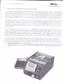
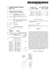
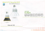
The Model l05PTM is a self conrained. drgrrai LCD. multi-function, precision
timing control device" that has
been specifically developed tbr use sith manr of rhe.{merican Beauty8 ..rir,""".
loia..,"_n systems and
power units that are currentlv available Thrs trmer module gives you ihe
ability to establish consistent and
repeatable dwell times that are accurate to s:thrn a hundredih ofa second.
fftis i111p-..J ,.neatabilur. :ei:s
eliminate the need for relying on an operators abrlrrr ro consistentlv respond to the
sold.r,"g;;;..r'.,r.. ,
being perlormed
-The
follorving set-up steps shos hos eas) :r is ro incorporate the timer module into your soije:-::::
>.,::e::
The precision timer module should be pluegec ,lrrecrlv into any standard
5-l5R NEMA I l0-i:.;.1-,-,..;
The footswitch plugs rnto the lorr voltage -i 5mm t'em;le jack on the lower front panel
of the rrme: :::o,ruie.
The American BeautyE resistance
poser units ilug into the 5-l5R NEMA re..piu.i.
,, .tro
-soldeiing
located on the lower front panel olthe
timer mo,lule. Thi l0-519 Footswitch with the pig!r:-ia.i snle plug
receptacle is not required because the prectsion timer module has its
own low voltage fol'tss lcn supplied.
.",
Carelully read all of the documentation included u'ith the timer module in
order to properll Jerermine the
appropriate function that should be used for 1-our specific resistance soldering
application ,.qu,r.-"ntr.
Each ofthe various functions that are available can be chosen by adjusting
tte ortpui rot. t.r.ctor to the
appropriate letter designator' The time range mode and time value are useJ to
determrne :he inten.al senine.
. This ltem is svailable in 220 ,'-lC upon requesl
High
Capaci$
Preckion
Timer
.llodule
l)lodel
|LSHCPTM)
is availablefor use virh C and D seiles power units.
'
' Alwals veilrt'ilre output mode ond the processing time selections are coieu before operaing
q'stem
).our sotdering
Sffis
Information & Instruction Manual for
American Beauty@ Resistance Soldering Equipment
Manufacturers of American Beauty@
Quality Soldering Tools
8.0 Troubleshooting Yow Equipment
Only authorized persons that have received training in tt. propi, servicin! ofelectrical equipment should
attempt to diagnose or malie repairs tJ an1 ol1'our American Beautyr'registance soldering equipment.
You rvill find that the most importail tool to have available when troubleshooting your risistance so.ldering
equipment will be a standard Ap v#-mrter or a multi-meter *rat has a setting forreadir:g the AC voltage.
.\'ever aftemDt to service yo,tf
anB
4'resista
the troubleshooting
stepilo follo\r nssuming that you have properly set up )-our soldering slsten
--,F'
t{ propQll pertbrm the soldering process before any problems have der.eloped.
Ifthe proper AC voltage ca4lnt be terified at each ofthe steps listed below, continue on with the next step
Th_ese are
and have already been able
1. Verifr that the proper.\c
'olrage
is being conducted into the handpiece's electrodes.
If proper AC voltage is available
at the eleCtrodes but no heat is being developed they may require cleanin5
where they make contact s'ith the'!ate metals. Contamination, dirt and bumt flux may encumber the curren
ilorv that is required from the crrnla!'t suriaces ofthe electrodes and through the base metals.
2. Veril],
that the proper AC voltage is being conducted to the electrode adapters.
Ifproper AC voltage is available rvithin the electrode adapters but unavailable from the electrodes be sure
that their contact surfaces have not become .onlaminated and that the electrodes have not become loosened
lvlalie sure that any set-scJ9ws tbat belong in rhe adapters are still in place and are properly tightened.
3. Verif,thattheproperACvolrageisbeingc.uducredtiomthepouerunit'soutputreceptacles.
tf proper AC voltage is aV$able at the power unit rrutput but is unavailable at the electrodes and adapters
be sure the handpiece is sgiurely connected to the poser unit and check the electrodes and adapters again.
If proper AC voltage is siill unavailable at the elecrrtrdes or the adapters the handpiece may ha-ve devilopec
a short in the cables, or ong ofthe wire conneclirrns mal have become loose. Ifyou are unable to determine
the source ofthe problent you may wish to rerum r..ur handpiece to the factory for an evaluation and repair
,
4. Verifothattheproporl20VAClinevoltageisarailablefromthereceptacleofthefootswitch'spig$.back plug assembly whgrl thq footsrvitch is beine depressed.
Ifproper line voltage is qvailable from the receptacle ..fthe footswitch's piggy-back plug assembly.but the
proper output is unavallaple from the porver unit. be sure that the power unit is tumed on and rhat the circuil
breaker has not been tripped. Ifthe circuit brealier has nlrr been tripped the problem may exist inside ofthe
power unit and you iiray wish to retum it to the facroq tbr an evaluition and repair.
5. Verifothattheproperl20VAClinevoltageisavailablefromthemainpowersupplyreceptaclethatthe
fbotswitch's piggy-back plug assembly was plugged inro.
If proper 120 VAC line voltage is available from the main porver receptacle but it is unar.ailable liom the
receptacle ofthe footswitch's piggy-back plug assembll )ou ma]'wish to retum vour tbots\ritch assembly
to the factory for an evaluation and repair.
You may find it easier to troubleshoot your resistance soldering system by following the verification steps
that are listed above in the reverse order (similar to the initial set-up procedures) tracing voltage fronr the
source until you reach the point where it becomes unavailable and then determining the exact cause.
You
willfrnd more Troubleshoofing information
available within the Support secfiott
ofour
Web-Site.
All American Beauty Resistance Soldering Systems are proudty manufactured in the U.S.A,, b1
Assembly Technologies rnternational, rnc. we are located at !177 w, Maple Road, ctawson Mi
48017' We can be found on the internet @ WWW.AMERICANBEAUTYTOOLS,COM or via telephone,
toll free at 800.550.2510,
Thank you for your business!
inaane
;
*EE
igfi
x;; isi atf,+ aic;rfg
IIaIiE
E EIE iiE EF Ei;
ae;iFE
5
35EE
1[q
lffi
iE
I;EEI
Eisi$srariF;iara;iiliEiEifr'i[Eiiii
: q
iEli
E =iE
l4 a8-fr
3
m
i
F
H
c)
ss :4 iiB
tH IEl ,EEilrtgl,11gfuaiigggfug1gi1ig1ilggE
2nl
s5
wc
rfl!
Ep
ie
ter
1n
7tF
]lt
a{
HH
az
ilo
2=
d
iel
d='iEil
;n
1
$
{i
Egi
eE is*a E
:**
[-* igi
tila
ro;F
F$''' EfE$3EiHil aI
+' ;e iE$
-iira
Ail $iE E$i
-*frEe
g1
Eg
ga ai
3ai i**
iiE
qs
a *e: $fli E;1 iig i; ii
$6
=s. $ i3
$ai
Fg
;i
I
si.3 ;? ;ii{ 5ad:5 sE tE
3
; a;g;.i* i;fi*;irir agegi
I
F
fi;gglggifl;aaiEfritaAE:
E'i;gE;ii+**iii+i1ii3
,e. K
,68
B e gt
B
;idq
;se
:il
,B
fd
qc Eej
inx
o-o
e;
=fl ;q
A
1
e
qtr iF
3 E
1g fr$ i
riA ;asgi
eFB$* iflnmE
en FEg
: ai
n6.
AFOc
Fc)
9{
mH
FO
2G
oT
ag
a
{
m
3
a
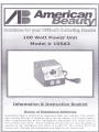
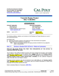
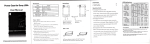
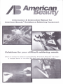
Description of your Product:
100 Watt Infinitely-Variable Power Unit. Input 110-t2A VAC 50/60 Hz, with 1
protection. Available in 220-240 VAC when special ordered as
model 105A3 22A. Output voltage is 0 to 2.65 VAC (no load). Control Knob
reads 0 to 100% of maximum output voltage. Output wattagg is adjustable
from 0 to 100 Watt maximum. Power Unit incdrporates Taper Pin connection
method. Product dimensions-3 3/4" x3 7/8" x 5". Product weight -2.5 lbs.
AMP clicuit
MODEL
DESCRIPTION
MAXIMUM
WATTAGE
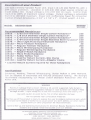
Recommended Han d pi eces:
10515 - 3132 Inch Diameter Single Carbon Handpiecex
225
LO572 L/8Inch Diameter Single Carbon Handpiece*
25O
10573 - 3/ 16 Inch Diameter Single Carbon Handpiece*
325
10552 - 5/64 Inch Diameter Single Stainless Steel Handpiece* 1OO
10578 - Ultra-Light Fixed Dual-Electrode Handpiece
225
105133 - Micro-Tweezer Handpiece
30
10541 - Regular Tweezer Handpiece
2OO
105131 - Micro Wirestripping Handpiece
30
tOStT - Regular Wirestripping Handpiece
tOO
10591 - Small V-Notch Handpiece
lOO
105 I23 - Micro Probe Handpiece
SO
105L42 - Solder Reflow Tool
100
10512 - Lead for Return Current-Std. Clamp
25O
10512A - Lead for Return Current-Alligator Clamp
1oo
* Lead for Return Current required for these handpieces
Applications:
Soldering, Heating, Thermal Wirestripping, Solder Reflow & SM D Removal.
Can be adapted to automated and fixtured production tooling. We strongly
recommend incorporating our Model 10519 Standard Footswitch with this
Power Unit.
WARNINGS
Maximum wattage that is shown reflects a 20-second suggested cycle duration.
Operating handpiece beyond suggested wattage or cycle duration can result in heat
damage tO tOOl. A higherwattage may be used when incorporating a shorterdwell (heating) time
Use with caution
to avoid burns, fire or other potential damage
Do not operate near combustible materials
Normal use of this product is likely to expose the user to solders containing lead, which
is known to the State of California to cause cancer and birth defects (or other reproductive harm) or other proposition 65 listed Chemicals.
General Set-up and Operating Instructions for American Beauty Resistance Soldering
Systems are located inside this booklet or on our website.
All American Beauty Soldering Tools are manufactured by
Assembly Technologies International, Inc.
II77 West Maple Road . Clawson Michigan 48017-1059
(248) 280-2810 . (248) 2BO-2878
WWW.AM
E
RICAN BEAUTYTOO LS. CO M