1
15
4,374,417
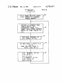
cording to block 172, the base address of the TVT table,
which is hexadecimal 8A00, is added to the doubled
TVT index stored in the HL registers. At this point, the
BL registers contain the correct address in the TVT
table for the page table entry being scanned.
Thereafter, according to block 174, the ROM page
register in page registers 32 is read and the data is stored
in bit positions 0-3 of the B register. In addition, the
paged section code, which is obtained from the D regis
ter, is stored in bit positions 4 and 5 in the B register. Bit
positions 6 and 7 are set to 0. Thus, byte 1 of the TVT
table entry is contained in the B register. Then, accord
ing to block 176, the contents of the B register is stored
16
transferring the program fetch operation to the patch
area of the RAM.
Assuming that the carry indicator is not set at block
190, then according to block 194, bits 5, 6 and 7 of the
A register, which contain the page section bits left
shifted one position, are transferred to the H register. At
this point in time, the H register contains a code of
hexadecimal 20, 40 or 60 and the L register contains the
offset to byte 2 of the proper page table entry.
Continuing at block 196, the offset into the paged
section contained by byte 1 and bits 0 through 4 of byte
in the TVT table at the address contained in the BL
2 of the address page table entry are transferred to the
HL registers. It should be noted that the page section
bits contained in the H register are maintained during
registers. The HL registers value is then incremented by
this transfer operation. Thus, the l-IL registers at this
one and the contents of the E register, which is the
offset to the current page table entry, is stored in the
TVT table at the address then contained in the I-IL
Then, according to block 198, the address contained in
point contains an address of the called program routine.
the BL registers is transferred to the program counter
(PC) in CPU 14 and at block 200, a continuation occurs
incremented by one and returned to block 170 occurs 20 with the program counter causing the fetching of in
structions from the new address therein and execution
and the next page table entry is scanned and transferred
of the called routine is begun.
to the TVT table. This continues until the end of the
Thus, it is seen that by using the simple routine de
table marker is identified at block 170.
scribed with respect to FIG. 10, the transfer of instruc
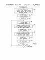
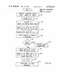
Referring now to FIG. 10, the program routine RSTl
is shown in a flow diagram format and is used whenever 25 tion execution between pages can be easily accom
registers. Thereafter, the contents of the DE register is
a transfer from one program module to another pro
gram module is to occur. The 8085 source code for the
RSTl program is shown in Appendix III. In the 8085
plished. This technique allows for simplicity in pro
gramming because it is not necessary to know the exact
location in read only memory of every program module
being developed during the development of the soft
microprocessor the RST instruction is used as a restart
instruction and automatically causes a predetermined 30 ware. One merely assigns a unique index code to a par
ticular program module as it is being programmed.
address located in unpaged ROM to be placed in the
Then that program module can be fit into a particular
program counter with the saving of certain information
page where room exists and maximum utilization of the
in the stack. On the next machine cycle, the instruction
memory can be achieved. In addition, the routine al
at the predetermined RST location will be executed.
The RSTl program shown in FIG. 10 utilizes this fea 35 lows for correcting the program modules by utilizing a
patch technique. If desired, the program modules can
ture of the 8085 microprocessor, such that whenever it
also be modi?ed by including all modi?ed program
is desired to cause a transfer from one program module
modules in the highest section of ROM. This section’s
to another, such as by the conventional call instruction
page table is scanned last and if an identical TVT index
or jump instruction, the calling sequence is the RSTI
number exists, the information previously in the TVT
instruction followed by a two byte NAME code which
table will be written over by the information in the
identi?es the particular module to be called and con
higher ordered ROM section.
tains the address of that program modulus entry in the
Several variations of the use of the paging technique
TVT index table. First, according to block 180, the
can be made to the technique described above. A three
saved return address which normally is the address
byte TVT entry could be used whereby the actual ad
immediately following the RSTI instruction is adjusted
to the address following the NAME code. Then, ac
cording to block 182, bytes 1 and 2 of the NAME code
dress of the new program module is stored in bytes two
and three. In this instance, direct addressing of the new
program module can occur without using the offset in
are stored in the BL registers and thus, the BL registers
the page table entry.
address the desired TVT table entry of the called pro
Another variation involves placing the TVT index of
gram. Thereafter, according to block 184, the accumu 50
program modules which are frequently called in a spe
lator, or A register, is cleared and the then existing
cial section of the TVT table. Such a special section
information in the ROM page register in page registers
may be, for example, between locations 8COO and
32 is read and saved on the stack.
8DFF and would contain TVT index between decimal
Then, according to block 186, the ?rst TVT table
256 and 511. For these program modules, a different
byte, which is then addressed by the HL registers, is
restart instruction would be used, and the NAME code
read from the random access memory and stored in the
could be a single byte. The single NAME byte is then
A register. The low four bits of information in the A
placed in the L register and hexadecimal 46 is placed in
register is then transmitted to page registers 32 to set the
the H register. Then the value in the HL registers are
ROM page register to the page speci?ed in byte 1 of the
doubled (due to the two byte length of each TVT table
TVT index for the called program. Thereafter, the BL
entry) and the processing continues as described from
register is incremented by 1 and the second TVT byte,
block 184 through 200. This procedure saves one byte
as then addressed by the HL registers, is read and stored
of storage each time one of these frequently used mod
in the L register. Then, according to block 188, the
ules is called.
second TVT byte is left shifted through carry one posi
It should be noted that conventional call and jump
tion and a determination is made at block 190 whether 65
instructions may be used when transferring to program
the carry indicator is set. If it is, a patch is indicated and
modules located in the unpaged ROM 22. Thus, the
as indicated in block 192, the patch area address is trans
most frequently called program modules should be
ferred to the H1 registers and processing continues by