1
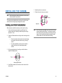
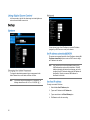
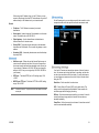
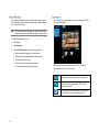
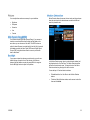
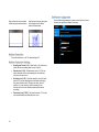
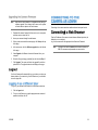
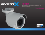
HD40D Night Vision HD Indoor/Outdoor IP Dome Camera User Manual HD40D: Night Vision HD Indoor/Outdoor IP Bullet Camera Operations Manual Manual Edition 32332AE– October 2015 ©2014, AvertX All Rights Reserved No part of this document may be reproduced by any means, electronic or mechanical, for any purpose, except as expressed in the Software License Agreement. AVERTX shall not be liable for technical or editorial errors or omissions contained herein. The information in this document is subject to change without notice. The information in this publication is provided “as is” without warranty of any kind. The entire risk arising out of the use of this information remains with recipient. In no event shall AVERTX be liable for any direct, consequential, incidental, special, punitive, or other damages whatsoever (including without limitation, damages for loss of business profits, business interruption or loss of business information), even if AVERTX has been advised of the possibility of such damages or whether in an action, contract or tort, including negligence. This software and documentation are copyrighted. All other rights, including ownership of the software, are reserved to AvertX. AVERTX, and AvertX, are registered trademarks of AVERTX in the United States and elsewhere; Windows is a registered trademarks of Microsoft Corporation. All other brand and product names are trademarks or registered trademarks of the respective owners. The following words and symbols mark special messages throughout this guide: WARNING: Text set off in this manner indicates that failure to follow directions could result in bodily harm or loss of life. CAUTION: AVERTX 2 Text set off in this manner indicates that failure to follow directions could result in damage to equipment or loss of information. 1. Read Instructions Read all of the safety and operating instructions before using the product. 2. Retain Instructions Save these instructions for future reference. 3. Attachments / Accessories Do not use attachments or accessories unless recommended by the appliance manufacturer as they may cause hazards, damage product and void warranty. 4. 5. Installation Do not place or mount this product in or on an unstable or improperly supported location. Improperly installed product may fall, causing serious injury to a child or adult, and damage to the product. Use only with a mounting device recommended by the manufacturer, or sold with the product. To insure proper mounting, follow the manufacturer's instructions and use only mounting accessories recommended by manufacturer. Operating Before using, make sure power supply and others are properly connected. While operating, if any abnormal condition or malfunction is observed, stop using the camera immediately and then contact your local dealer. Handling Do not disassemble or tamper with parts inside the camera. Do not drop or subject the camera to shock and vibration as this can damage camera. Do not block the cooling holes on the bracket. This camera has a cooling fan inside the housing. Blocking the cooling holes will cause heat to build up and cause malfunction. Care must be taken when you clean the clear dome cover. Scratches and dust will ruin the image quality of your camera. Do not use strong or abrasive detergents when cleaning the camera body. Use a dry cloth to clean the camera when it is dirty. In case the dirt is hard to remove, use a mild detergent and wipe the camera gently. Power source This product should be operated only from the type of power source indicated on the marking label. Installation and Storage Do not install the camera in areas of extreme temperatures in excess of the allowable range. (14°F~ 122°F / -10°C ~ 50°C) Avoid installing in humid or dusty places. The relative humidity must be below 90%. Avoid installing in places where radiation is present. Avoid installing in places where there are strong magnetic fields and electric signals. Avoid installing in places where the camera would be subject to strong vibrations. Never face the camera toward the sun. Do not aim at bright objects. Whether the camera is in use or not, never aim it at the sun or other extremely bright objects. Otherwise the camera may be smeared and damaged. This device complies with Part 15 of the FCC Rules. Operation is subject to the following two conditions: (1) this device may not cause harmful interference, and (2) this device must accept any interference received, including interference that may cause undesired operation. This symbol on the product or on its packaging indicates that this product shall not be treated as household waste in accordance with Directive 2002/96/EC. Instead it shall be handed over to the applicable collection point for the recycling of electrical and electronic equipment. By proper waste handling of this product you ensure that it has no negative consequences for the environment and human health, which could otherwise be caused if this product is thrown into the garbage bin. The recycling of materials will help to conserve natural resources. For more details information about recycling of this product, please contact your local city office, your household waste disposal service or the shop where you purchased the product. Compliance is evidenced by written declaration from our suppliers, assuring that any potential trace contamination levels of restricted substances are below the maximum level set by EU Directive 2002/95/EC, or are exempted due to their application. DANGEROUS HIGH VOLTAGES ARE PRESENT INSIDE THE ENCLOSURE. REFER SERVICING TO QUALIFIED PERSONNEL ONLY. . 4 TABLE OF CONTENTS................................................................................................................................................................................................................... 5 INTRODUCTION .............................................................................................................................................................................................................................. 8 Overview .................................................................................................................................................................................................................. 8 Camera Default Settings ................................................................................................................................................................................... 8 Product Features ............................................................................................................................................................................................... 8 ONE: GETTING STARTED ............................................................................................................................................................................................................. 9 Box Contents .......................................................................................................................................................................................................... 10 Camera Overview ................................................................................................................................................................................................... 10 Dimensions...................................................................................................................................................................................................... 10 Side .......................................................................................................................................................................................................... 10 Front ......................................................................................................................................................................................................... 10 Connections .................................................................................................................................................................................................... 11 Weather Resistant Cable Connector ........................................................................................................................................................ 11 TWO: CAMERA FINDER ............................................................................................................................................................................................................... 12 Bench test............................................................................................................................................................................................................... 13 AvertX Camera Finder ..................................................................................................................................................................................... 13 Finding IP Cameras.................................................................................................................................................................................. 13 Accessing the Camera ............................................................................................................................................................................. 13 Changing the IP Address ......................................................................................................................................................................... 13 THREE: SETUP AND CONFIGURATION ..................................................................................................................................................................................... 14 Installing the Camera.............................................................................................................................................................................................. 15 Ceiling and Wall Installation ............................................................................................................................................................................ 15 Removing the Lens Cover ............................................................................................................................................................................... 16 Installing the Desiccant.................................................................................................................................................................................... 16 Resetting the Camera ..................................................................................................................................................................................... 16 MicroSD Card .................................................................................................................................................................................................. 16 Connecting to the Camera ...................................................................................................................................................................................... 18 Connecting In a Web Browser ......................................................................................................................................................................... 18 Administrator/User Privileges .......................................................................................................................................................................... 18 Default Username and Password ............................................................................................................................................................. 18 Connecting a Stream ....................................................................................................................................................................................... 18 Camera Settings ..................................................................................................................................................................................................... 19 Viewer Tabs .................................................................................................................................................................................................... 19 Home ............................................................................................................................................................................................................... 19 Changing the Language ........................................................................................................................................................................... 19 Using Digital Zoom Control ...................................................................................................................................................................... 20 Setup ............................................................................................................................................................................................................... 20 System ..................................................................................................................................................................................................... 20 Streaming ................................................................................................................................................................................................. 21 Camera .................................................................................................................................................................................................... 22 Motion Detection ...................................................................................................................................................................................... 23 Software Upgrade .................................................................................................................................................................................... 24 Logout ............................................................................................................................................................................................................. 25 Logging In as a Different User .................................................................................................................................................................. 25 Connecting to the Camera as Admin ...................................................................................................................................................................... 25 Connecting in a Web Browser ......................................................................................................................................................................... 25 Home ............................................................................................................................................................................................................... 26 Admin Camera Controls ........................................................................................................................................................................... 26 System ............................................................................................................................................................................................................ 27 Security .................................................................................................................................................................................................... 27 Network .................................................................................................................................................................................................... 28 DDNS ....................................................................................................................................................................................................... 29 Mail........................................................................................................................................................................................................... 29 FTP .......................................................................................................................................................................................................... 29 HTTP ........................................................................................................................................................................................................ 30 Events ...................................................................................................................................................................................................... 30 6 Storage Management ............................................................................................................................................................................... 31 Recording ................................................................................................................................................................................................. 32 Schedule .................................................................................................................................................................................................. 32 File Location ............................................................................................................................................................................................. 32 View Information ...................................................................................................................................................................................... 32 Factory Default ......................................................................................................................................................................................... 33 Software Version ...................................................................................................................................................................................... 33 Software Upgrade .................................................................................................................................................................................... 33 Maintenance ............................................................................................................................................................................................. 33 Streaming ........................................................................................................................................................................................................ 33 Video Format ............................................................................................................................................................................................ 33 Camera............................................................................................................................................................................................................ 35 FOUR: SPECIFICATIONS ............................................................................................................................................................................................................. 37 Camera Specifications ............................................................................................................................................................................................ 38 32332AA 7 8 Progressive Scan CMOS Sensor 1080p and 4MP Resolution Available H.264 Encoding The HD40IR Night Vision HD Indoor/Outdoor IP Bullet Cameras are compact cameras designed for easy setup and use. The 4 megapixel resolution provides high definition images. The HD40IR camera also offer quad streaming and can be used in a variety of installations including shops, stores, banks, factories and for building surveillance. Dual Streaming Multi-Language Support Tampering Alarm Digital Wide Dynamic Range With Power over Ethernet (PoE), the need for separate power lines is eliminated and cabling and installation costs can be significantly reduced. The light weight, and small size of the camera make installation easy in a variety of locations. Motion Detection Privacy Masks Smart Picture Quality / 3D Noise Reduction The HD40IR includes Digital Wide Dynamic Range, 3D Noise Reduction, and Day/Night ICR, making it useful for challenging lighting conditions and nighttime installations. Network Failure Detection Digital Day/Night (ICR) IR LED Module (working distance up to 30m) MicroSD Support (up to 128GB microSD Card) Weatherproof (IP66 Outdoor Rated) ONVIF Support IP Address 192.168.0.250 Username admin Password 1234 Management Port 80 Streaming Port (RTSP) 554 Box Contents Camera Overview 32332AE 9 Before proceeding, please check that the box contains the items listed here. If any item is missing or has defects, DO NOT install or operate the product and contact your dealer for assistance. HD40IR Camera Desiccant Self-Tapping Screws Plastic Screw Anchors Quick Start Guide 10 Before installing or connecting the camera, please refer to this section and complete preparations for setup and all switch settings. AvertX HD40IR cameras use Power over Ethernet (PoE). The only connection on the camera is the RJ45 Ethernet dongle located on the rear of the camera. Connect one end of the Ethernet cable to the dongle, and connect the other end to the recorder, or to a PoE switch. Protect the network cable connection from water damage by running the cord inside a wall or ceiling, or through conduit. If passing the cord through a wall or ceiling, drill a 3/4” hole. For outdoor installations, seal any holes in the wall or ceiling with silicone caulk to protect against water intrusion. This camera features an IP66-rated weather resistant connector. For unprotected outdoor connections, screw the connector on the included Ethernet camera cable onto the camera dongle. If your installation location does not require a water resistant connection, loosen and slide the connector back on the cable until it’s out of the way. Connecting the IP66 water resistant connector requires unscrewing the thread lock cap and sliding back all parts of the assembly. Refer to instruction card for more information. AvertX recommends using Category 5 Ethernet cable to connect the camera to your network. For the best transmission quality, the cable length should not exceed 328 feet (100 meters). Once you have connected the camera, check the status of the network connection by looking at the link indicator and activity indicator LEDs. If the LEDs are not lit check your network connection. The green link LED indicates a network connection and the orange activity LED flashes to indicate network activity. 32332AE CAUTION: Do not attempt to disconnect the camera connection without loosening the smaller thread lock cap. Do not force. Forcing the assembly will break the camera dongle and will void camera warranty. 11 AvertX IP Finder 12 AvertX recommends that you perform a bench test of your camera before installation. This will confirm that your camera is functioning correctly and familiarize yourself with the functions before it is installed and possibly out of reach. To bench test your camera, attach the camera network connector to your recorder and test whether or not the camera is functioning correctly. Once the camera is connected to the recorder, test all functions to ensure proper operation. If the camera will not connect or is not functioning correctly, do not install and contact AvertX Support. The Camera Finder application is available to download at avertx.com. 1. Open the folder where you downloaded Camera Finder. 2. Click Camera Finder. 3. Click Device Search on the Device Search window. 4. If a Windows Security Alert window opens, click Unblock to allow the IP utility to access your network. 5. Click Device Search again to find all connected IP devices. Tip The default IP address of your IP camera is 192.168.0.250 Note If you cannot connect to the camera you may need to change the camera’s IP address to match your network settings. 32332AE You can view live video and access the camera configuration by accessing the camera in an internet browser. 1. Right-click the desired network device and select Browse. 2. Type the default username and password in the login window to access the video server using your internet browser. If you are not directly connecting to an AvertX HDIP recorder, you must manually change the IP address. Change the IP address to a number in the same subnet as your existing network or to the recommended network settings for your network. 1. Right-click the desired network device and then click Network Setup. 2. Select the Static IP option. 3. Enter the new IP Address, Gateway, Netmask, and DNS for camera. The Mighty Squirrel Contr oller 13 Installing the Camera Connecting to the Camera Viewer Software 14 Note: 5. Adjust the position of your camera. 6. Tighten the screw to secure your camera. Before installing this camera, please refer to the Quick Start Guide included in the camera box. Screw The camera can be installed directly onto the wall or ceiling. Be sure that the structure is strong enough to support the camera. Adjust aim Bullet cameras are suitable for mounting on either a wall or ceiling. 1. Use the included mounting template to pre-drill holes for the mounting screws and, if passing the cable through the ceiling or wall, drill a ¾” hole. 2. Connect the Ethernet cable from ceiling or wall to the dongle on the camera. 3. Protect the network cable connection from water damage by running the cord inside a wall or ceiling, or through conduit For outdoor installations, seal any holes in the wall or ceiling with silicone caulk to protect against water intrusion. Note HD40IR cameras are equipped with a seal inside the housing to prevent moisture from entering. If you have any concerns about moisture entering the housing or wall through the cable egress, AvertX recommends sealing the opening at the wall and at the base of the camera with silicone caulking. Affix the mounting bracket to the ceiling or wall with the three supplied self-tapping screws. Screw Screw Mounting Bracket Base 4. Use a Phillips screwdriver to loosen the screw on the side of the bracket mount. 32332AE 15 You may need to remove the lens cover from the camera to access the reset button, microSD card, or focus the camera. Unfasten the screw on the camera housing and remove the front cover If it is necessary to reset the camera to the factory default settings, hold down the Reset button (see Camera Overview) for 30 seconds. This will return all settings, including network setup, to the factory default. The IP address of the camera will return to 192.168.0.250. SD CARD SLOT To prevent condensation on the glass cover, the HD90IR has a desiccant packet installed inside the housing of the camera. If condensation appears, replace the desiccant packet with the replacement packet included in your camera packaging 7. Unfasten the screw on the camera housing and remove the front cover 8. Remove the desiccant packet from the camera. 9. Carefully tear open the aluminum envelope for the new packet, and remove the desiccant. 10. Remove paper backing from the adhesive strip on the desiccant packet. 11. Place the desiccant firmly in the position indicated here. 12. Reinstall the front cover and fasten the screw RESET BUTTON Your camera includes a microSD card slot, which can be used for emergency video backup. The microSD card is not included. You must remove the cover of the camera to access the microSD card slot. You can use any class MicroSDHC card up to 128GB. This will hold approximately 15 hours of video at 15 FPS 4MP resolution. It saves the video files on the SD card in a series of 5 minute long .avi files, and you can access the recordings via any card reader that reads MicroSD cards. NOTE: The microSD card needs to be formatted to FAT32. A formatting utility is available at avertx.com 16 To enable recording to the microSD card, insert the card into the camera and then you will need to enable recording using the camera software. 13. Open Microsoft Internet Explorer (IE) web browser. 14. If your camera is connected directly to the HDIP recorder: Type the IP address of the recorder, followed by : and then /admin. (example: http://10.1.10.15:83/admin) a. - Using the default web port (80), the camera uses an address based on the IP address of the HDIP recorder starting with port 81. Camera 3 will be port 83 and camera 11 would be port 91. b. - If using a unique web port, identify the correct web port at Menu > Network > Webport If your camera is connected to an external PoE switch, type the IP address of the camera in the address bar of the web browser followed by /admin. (example: http://10.1.10.27/admin) 15. Type the user name and password of the camera in the pop up window. - The default username is admin and the password is 1234 17. Ensure the camera is reading the card. Under Device Information, the Free space will have a number corresponding with the size of the card. 18. Click Recording, on the left menu bar, and ensure that under Recording Storage the SD Card option is selected. NOTE: Do not change the username account/password on the camera software 16. After logging in, go to System > Storage Management > SD Card 19. Under Recording Schedule, click the Always option. 20. Click Save to apply the settings. 32332AE 17 AvertX IP cameras are optimized for use with AvertX HDIP recorders, but you can also connect to your AvertX IP cameras using third party software like VLC media player (http://www.videolan.org). 1. 2. Type the IP address of the camera in a web browser. or Use the included Camera Finder software and locate the camera on the IP Finder list, then double-click the camera to open the Viewer software in your web browser. Log in to the camera with the appropriate User Name and Password. Note The default User name is admin and the default Password is 1234. The username and password are case sensitive. The Administrator account has the authority to configure the IP camera and authorize users’ access to the camera. The User accounts have access to the camera with limited authority. The username and password are case sensitive. It is strongly recommended that the password be changed after the initial setup to prevent unauthorized access. Username – admin Password – 1234 18 To connect the camera you may need to provide the stream URL. All AvertX IP cameras are capable of delivering two RTSP streams, as well as streaming MJPEG over HTTP. The stream URLs are listed below. rtsp://<ip address>/mjpeg rtsp://<ipaddress>/h264 http://<ipaddress>:8008 The MJPEG over HTTP stream is identified by a port number. The default port is 8008; this port can be configured in the camera’s System page (click Setup, and then click System). You can access the camera setup menu using an internet browser on your computer. The camera viewer software will install automatically the first time you connect to the camera. If your internet browser doesn’t install the viewer software, check the security settings or ActiveX controls and plug-in settings. If your internet browser asks for permission to install the plugin, you must allow ActiveX or Quicktime to install to continue the installation. ActiveX and Quicktime are used to view the camera's video in this management interface module. Select the video stream you want to view, H.264-1 (stream 1) or H.2642 (stream 2). Note Advanced users can access additional video stream options, including the MJPEG stream, through the admin panel. The default when viewing your camera using the web. Use this to make the image smaller. This can save bandwidth if necessary. Home – Monitor live video. Setup – Set the host name , root password, and network related settings, modify the video resolution, adjust the Camera parameters, set Motion Detection options, and view and update the camera software. This will show your video at full screen on your monitor. To exit full screen mode, double-click the video. Logout – Change user. Note 32332AE For advanced management options, access the camera’s admin panel by adding “/admin” after the camera’s IP address in your browser’s address bar. 1. Click the Language drop down menu 2. Select a language. The browser will refresh, then display the selected language. 19 In full screen mode, right-click the video image to activate digital zoom and use the scroll wheel to zoom in/out. You can choose to use a fixed IP address or a dynamic IP address (assigned by a DHCP server or router) for the camera. The camera comes preconfigured with a fixed IP address, selecting Get IP address automatically requires a router or DHCP server to assign an IP address to the camera. Note To change the administrator password, type a new password in the Admin Password box, confirm below, and then click Save. Note Every network device has a unique Media Access Control (MAC) address that can be used for identification. The MAC address is located on the bottom of each camera, and on the box label (AvertX IP Finder also displays the MAC address for identification). Record your camera’s MAC address for identification in the future. The maximum length of the password is 14 characters. The following characters are valid: A-Z, a-z, 0-9, !#$%&’-.@^_~. To assign a new static IP address: 20 1. Select the Use fixed IP address option. 2. Type a new IP address in the IP address box. 3. Type a new address in the Default Gateway box. 4. Click Save to confirm the new setting. When using static IP address to log in to the IP Camera, you can access it either through the AvertX IP Finder software or type the IP address directly in the Address bar of your internet browser. General IP address – The IP Address is necessary for network identification. Subnet mask – Used to determine if the destination is in the same subnet. The default value is 255.255.255.0. Default gateway – Used to forward frames to destinations in different subnets or for internet access. Primary DNS – The primary domain name server that translates hostnames into IP addresses. This is usually the gateway or router address. Secondary DNS – A secondary domain name server that backups the primary DNS. Web Server port – Defines the port that Internet Explorer uses to connect over the web and view video. If this port is changed then the new port must be defined when attempting to web connect (ex: if your camera’s IP address is 192.168.0.100 and you change the web port to 8001, then you must type http://192.168.0.100:8001 in your browser). RTSP port – The default RTSP port is 554; setting range: 1024 ~65535. MJPEG over HTTP port – The default HTTP Port is 8008; setting range: 1024 ~65535. Note The MJPEG over HTTP port must not be the same as the web server port. On the Streaming tab, you can configure specific video resolution, video compression mode, and video protocol and audio transmission mode. Your AvertX IP camera can transmit two streams of video at the same time. One stream can be in high definition for recording, and the other can be a lower resolution used for live display. By using dual streams, you can display more cameras on the monitor of your recorder without taxing the CPU. Resolution – Set the resolution for each stream. GOP – Set the Group of Pictures (GOP) size for each stream. This setting can affect image quality and bandwidth. Please consult with technical support before changing this setting. Bit Rate – Set the data transmission speed for your camera. A lower bit rate will result lower image quality but a smaller file size and more bandwidth availability. Frame Rate – Set the frame rate of each stream. A lower frame rate will result in more bandwidth availability. 32332AE 21 If your camera is installed on a wall or table top the image may appear to be upside down. Rotate the camera video image using the software to get a right-side-up image. Note You can adjust your picture quality on both streams using the Camera section of the Setup tab. You cannot rotate the video image 90° to get a vertical image. Rotating the image 90° will stretch and distort the video image. To rotate the camera video image: 1. Click Setup. 2. Click Streaming. 3. From the Video Rotation list, select the desired rotation. Normal transmits the image as the camera sees it. Flip transmits the image backwards and upside down. Mirror transmits a mirror image. Rotate 90 degree clockwise/counterclockwise 180 degree transmits the image upside down. Select the video stream you want to adjust (H.264-1 or H.264-2). There are three options for viewing video: The default when viewing your camera using the web. Use this to make the image smaller. This can save bandwidth if necessary. This will show your video at full screen on your monitor. To exit full screen mode, double-click the video. 22 You can adjust these values as necessary for your installation. Brightness Sharpness Saturation Hue Contrast Motion Detection allows the camera to detect motion and trigger alarms when the motion level in the detected area exceeds the determined sensitivity threshold value. Your camera includes Digital Wide Dynamic Range. If your camera is aimed at an area that includes direct sunlight and dark shade in the same frame, you can lose some of the detail. The WDR function can adjust for these differences to provide detail for both the fully lit area and the shaded area within the frame. Digital WDR uses the Digital Signal Process (DSP) to brighten darker areas of a scene to provide more detail in dark shade. If your camera is aimed at a doorway or window, and you need to see detailed footage of people in front of that doorway, the difference between light and shadow can make the people difficult to recognize. Use the Backlight function to adjust for this problem. In the Motion Detection page, there is a motion detection window (red box) displayed on the Live View Pane. The Motion Detection window defines the motion detection area. To change the size of the Motion Detection window, drag the edge of the frame to resize. You can add up to 10 motion detection windows. 32332AE Click add under the Live View Pane to add a Motion Detection window. To delete a Motion Detection window, use the mouse to select the frame and click delete. 23 When motion detection is activated, the Motion pop-up window will open. When motion is detected, the signals will be displayed on the Motion window as shown below. Turn motion detection on or off. The default setting is Off. 24 Sampling pixel interval [1-10] – Default value is 10, which means system will take one sampling pixel for every 10 pixels. Detection level [1-100] – Default detection level is 10. This item sets the detection level for each sampling pixel; the smaller the value, the more sensitive it is. Sensitivity level [1-100] – The default sensitivity level is 80, which means if 20% or more sampling pixels are detected as changing, the system will detect motion. The bigger the value, the more sensitive it is. As the sensitivity value is increased, the red horizontal line in the motion indication window will be lowered accordingly. Time interval (sec) [0-7200] – The default interval is 10. The value is the interval between each detected motion event. Use the Software Upgrade page to view the current version of camera firmware, and upgrade the firmware if necessary. Note Make sure the new firmware file is available before starting a software upgrade. Do not change the file name, or the system will not be able to update to the new firmware. 1. Download the camera firmware file from avertx.com to a computer and then unzip or extract the file. 2. Access your camera through the web browser. 3. When you have accessed the camera page, click Setup at the top of the page. 4. In the setup menu, click the Software upgrade tab on the left side of the page. 5. Under Upgrade click Browse to locate the firmware file on your computer. 6. Select the file type (uImage_userland) from the list under Step 2. 7. Click Upgrade. The system will check the upgrade file, and then upload the file. The upgrade status bar will display on the page. Connecting to the camera as admin enables advanced setup and control. Type the IP address of the camera in a web browser followed by /admin (for example: xxx.xxx.x.x/admin). Log in to the camera with the appropriate User Name and Password. Note The default User name is admin and the default Password is 1234. The username and password are case sensitive. Your AvertX camera will automatically log you out when you close your browser window. If you want to log in as a different user, you will need to use the logout tab. To log in to your camera as a different user, follow these instructions. 1. Click the Logout tab. 2. To log in as a different user, type the appropriate user name and password, and then click OK 32332AE 25 The Admin Camera Controls gives greater control of camera functions. 26 Camera Control– Allows the User to change camera controls in the Setup menu. Host Name – The Host Name is used to identify the camera on your system. If camera based Motion Detection is enabled and is set to send alarm message by Mail/FTP, the host name entered here will display in the alarm message. 3. Click Add. 1. Select the user name on the User Name list. Time Zone – Select your time zone. 2. Click Delete to remove the user. Time Format – Select your desired time format. 3. Click OK in the confirmation window. Sync With Computer Time – Select to synchronize the camera date and time with the connected recorder. Note: Sync with NTP Server – Manual allows you to define the date and time manually. Network Time Protocol (NTP) is an alternate way to synchronize your camera’s clock with a NTP server. Specify the server you wish to synchronize in the NTP Server box. Then select an Update Interval. For more information about NTP, visit www.ntp.org. The Administrator account has the authority to configure the IP camera and authorize users’ access to the camera. The User accounts have access to the camera with limited authority. 1. Select the user name on the User Name list. 2. Click Edit. 3. In the resulting window, modify the Password and/or feature permissions. 4. Click Save. Note: To change the administrator password: 1. Type a new Administrator Password, and then type again to confirm the password. 2. Click Save. The user name and passwords are limited to 16 characters with no spaces permitted. There is a maximum of twenty user accounts. 1. Type the new Username and Password. 2. Select I/O Access, Camera Control, Talk, and/or Listen as permissions for the User. There is a momentary wait time while the Network Camera Manager saves parameters. When this period is complete, the User will be deleted. For security reasons, every time the user properties are opened the access check boxes are automatically cleared. Make sure you select any user access options each time you edit the user properties. HTTPS allows secure connections between the IP Camera and web browser that protects camera settings or Username/Password info from snooping. To use HTTPS, you are required to install a self-signed certificate or a Authority (CA) -signed certificate. The HTTPS certificate can be obtained by either creating and sending a certificate request to a CA or creating a self-signed HTTPS certificate I/O Access – All functions in the Setup and Advanced menus are available to the User. 32332AE 27 IP Filtering allows you limit access to your IP cameras by IP address. You can “Allow” or “Deny” a specific IP address by adding it to the appropriate list. IP addresses on the “Allowed IP List” will be able to access the IP camera. IP addresses on the “Deny IP List” will NOT be able to access the IP camera. This is a well supported security protocol commonly used by wireless vendors. This security method requires a valid CA certification and key. When properly configured, all communication between the client (usually a recorder) and the camera is encrypted. The camera comes preconfigured with a fixed IP address, selecting Get IP address automatically requires a router or DHCP server to assign an IP address to the camera. Note: Every network device has a unique Media Access Control (MAC) address that can be used for identification. The MAC address is located on the bottom of each camera, and on the box label (AvertX Camera Finder Software also displays the MAC address for identification). Record your camera’s MAC address for identification in the future. To set up a new static IP address: 1. Select the Use static IP address option. 2. Type a new IP address in the IP address box. 3. Type a new address in the Default Gateway box. When using static IP address to log in to the IP Camera, you can access it either through AvertX Camera Finder software or type the IP address directly in the address bar of Internet Explorer. 28 IP Address – The IP Address is necessary for network identification. Subnet mask – Used to determine if the destination is in the same subnet. The default value is 255.255.255.0. Default gateway – Used to forward frames to destinations on different subnets or for internet access. Primary DNS – The primary domain name server that translates hostnames into IP addresses. Secondary DNS – A secondary domain name server that backups the primary DNS. Web Server port – Defines the port that Internet Explorer uses to connect over the web and view video. If this port is changed then the new port must be defined when attempting to web connect (ex: if your camera’s IP address is 192.168.0.100 and you change the web port to 8001, then you must type http://192.168.0.100:8001 in your browser). RTSP port – The default RTSP port is 554; setting range: 1024 ~65535. MJPEG over HTTP port – The default HTTP Port is 8008; setting range: 1024 ~65535. HTTPS port – The default HTTPS Port is 443; setting range: 1024 ~65535. Note: No port number can be used in duplication on more than one item. 31186AE 33 IPv6 Address Configuration IPv6 Address Configuration – To enable IPv6 select Enable IPv6 and click Save. See your network administrator if you are unsure of your network configuration. Friendly Name – Set a name to easily identify the camera. DDNS (Dynamic Domain Name Service) is a service that allows a connection to an IP address using a hostname (URL) address instead of a numeric IP address. Most Internet Service Providers use Dynamic IP Addressing that frequently changes the public IP address of your internet connection; this means that when connecting to the camera over the internet, you need to know if your IP address has changed. DDNS automatically redirects traffic to your current IP address when using the hostname address. Enable DDNS – Select the check box to enable DDNS. Provider – Select a DDNS host from the Provider list. Host name – Type the registered domain name in the field. Username/E-mail – Type the username or e-mail required by the DDNS provider for authentication. Password/Key – Type the password or key required by the DDNS provider for authentication. Quality of Service allows you to prioritize network traffic services of the camera’s functions. The QoS function utilizes the Differentiated Services prioritized using Codepoint vales (DSCP). Note: Routers and switches on the network must be QoS or DSCP capable, and have these settings enable for this function to operate on your network. With Simple Network Management Protocol (SNMP) enabled, the camera can be monitored and managed remotely with a network management system. Contact your network administrator if you are not familiar with SNMP setup. Enable UPnP – When enabled, the camera will appear in My Network Places on Windows computers running UPnP on the same network. The camera can send an e-mail via Simple Mail Transfer Protocol (SMTP) when a variety of events occur. SMTP is a protocol for sending e-mail messages between servers. SMTP is a relatively simple, textbased protocol, where one or more recipients of a message are specified and the message text is transferred. Two sets of SMTP accounts can be configured. Each set includes SMTP Server, Account Name, Password and E-mail Address settings. For SMTP server, contact your network service provider for more specific information. The camera can send alarm messages to a specific File Transfer Protocol (FTP) site when motion is detected or when the sensor input is activated. You can assign alarm messages to up to two FTP sites. Enable UPnP Port Forwarding – When enabled, the camera will attempt to open the web server port on the router automatically. 32332AE 29 The camera can send alarm messages to a specific Hypertext Transfer Protocol (HTTP) site when motion is detected or when the sensor input is activated. You can assign alarm messages to up to two HTTP sites. When motion detection is activated, the Motion pop-up window will open. When motion is detected, the signals will be displayed on the Motion window as shown below. Motion Detection allows the camera to detect motion and trigger alarms when the motion level in the detected area exceeds the determined sensitivity threshold value. Turn motion detection on or off. The default setting is Off. In the Motion Detection page, there is a motion detection window (red box) displayed on the Live View Pane. The Motion Detection window defines the motion detection area. To change the size of the Motion Detection window, drag the edge of the frame to resize. You can add up to 10 motion detection windows. 30 Click add under the Live View Pane to add a Motion Detection window. To delete a Motion Detection window, use the mouse to select the frame and click delete. Sampling pixel interval [1-10] – Default value is 10, which means system will take one sampling pixel for every 10 pixels. Detection level [1-100] – Default detection level is 10. This item sets the detection level for each sampling pixel; the smaller the value, the more sensitive it is. Sensitivity level [1-100] – The default sensitivity level is 80, which means if 20% or more sampling pixels are detected as changing, the system will detect motion. The bigger the value, the more sensitive it is. As the sensitivity value is increased, the red horizontal line in the motion indication window will be lowered accordingly. Time interval (sec) [0-7200] – The default interval is 10. The value is the interval between each detected motion event. Specify which actions the camera should take when motion is detected. Send Alarm Message by FTP / E-mail – Select to send an alarm message to a configured FTP and/or e-mail address when motion is detected. When sending to email, the alarm notification is text only. When sending to FRP, the alarm notification will upload a text file to the FRP location. Upload Images by FTP – Select to assign an FTP site and configure various parameters as shown in the figure below. When motion is detected, event images will be uploaded to the appointed FTP site. 3. Designate the Trigger Action using the appropriate checkbox, and then use the dropdown menus to further manage the Trigger Action. Upload Image by E-mail – Select to assign an e-mail address and configure various parameters as shown in the figure below. When motion is detected, event images will be sent to the appropriate email address. 4. Type a file name, and then choose how the file name is multiplied for multiple files. Note: Make sure SMTP or FTP configuration has been completed. See the Mail and FTP sections for more information. Add date/time suffix – add the date/time to the end of the file name for each interval file saved. Add sequence number suffix – add a sequence number suffix to the end of the file name for each interval file saved. Add sequence number suffix up to x and start over – add a sequence number suffix to the end of the file name for each file saved up to x, and then start over. Enter a file name in the box, ex. Image.jpg. The uploaded image’s file name format can be set in this section. Select the one that meets your requirements. Overwrite – overwrite each previous interval file with the new interval file. Network Failure Detection – Turn the Network Failure Detection On, Off, or On By Schedule. Manual Trigger allows you to trigger an alarm event and specify which actions the camera should take when it’s triggered. Detection Type – Designate the IP Address that will be tested and how often (in minutes). To Manually Trigger an event, click the controls. button in the camera Triggered Action – Designate the actions that will occur upon Network Failure Detection activation. Tampering Alarm – Turn the Tampering Alarm On, Off, or On By Schedule. Tampering Duration – Designate the amount of time (in seconds) that tampering must occur in order for a Tampering Alarm to activate. Triggered Action – Designate the actions that will occur upon a Tampering Alarm activating. Periodical recording allows you to record in consistent intervals and save the files for later viewing. 1. Turn Interval Recording On or Off. 2. Designate the Time Interval (seconds). 32332AE All AvertX IP cameras include an integrated microSD™ card slot that can be used to record video or images. The card slot is compatible with a microSD™ card up to 128GB. Load Device Information – Displays the storage total size and free space information of the included microSD™ card. Current Recording Partition – Amount of space designated for recording on the microSD card. Format – Allows you to format the microSD card. Eject – Safely eject the microSD card. Recording List – Displays a list of files saved to the card. You can delete files from the card, or save them to your local PC. 31 Note: If you are using Windows Vista, 7, or 8, you will need to change the Snapshot location. Windows UAC does not allow internet programs to write directly to C:\ for security reasons. Network Share is a network protocol that runs a variety of different system platforms, allowing for file sharing between computers operating on Windows and computers operating on Unix. This serves as an additional storage type. Configuration requires the host IP address, share name, and credentials. Once configured, cameras can record events to the network share. 4. Type a Start Time and Duration. 5. Click Save. 6. Repeat steps 3-5 for each desired day of the week until the desired schedule is completed. Note: Start Time and Duration are measured in 24-hour format (HH:MM).Recording Schedule To delete a recording schedule: Select Disable for the type of Recording Schedule. —OR— Note: Network Share can be hosted on a Windows, Mac, or Linux system. Click on the desired weekday schedule and then click Delete. To create a schedule: The recording schedule allows you to set up scheduled recording to the microSD™ card or to Network Sharing. 1. Select a Schedule set (1-10). 2. Check the desired week day check boxes. 3. Select Day or Night. This section allows you to define recording schedules for the camera. 4. Designate a Start Time and Duration. For continuous recording: 5. Click Save. 1. Select type of Recording Storage. microSD card™: save recorded data to the microSD™ card located in the camera. Network Share: save recorded data to the designated Network Share location. 2. Select Always as the type of Recording Schedule. 3. Click Save. To set up scheduled recording: 32 1. Select type of Recording Storage. 2. Select Only during time frame as the type of Recording Schedule. 3. Use the appropriate check box to designate a day of the week. Set the destination of snapshot photos and recorded video files on your local computer. Log File User Information Parameters 6. There are two factory default settings available: Full Restore that restores default settings including network settings, and a Partial Restore that restores default settings excluding network settings. A system reboot is also available; this preserves all settings. Note: If a Full Factory Default is used, you will need to use the Network Camera Manger to find the desired camera(s) again. Software Version lists the software and mcu version currently installed on your camera. New versions of camera firmware is available periodically and can be found at http://www.avertx.com/product-downloads/. Note: 1. Make sure the software upgrade file is available before starting the software upgrade. Click Browse and find the upgrade file. Note: Do not change the file name, or the system will fail to find the file. 2. Select the file name from the list under Step 2. 3. Click Upgrade. The system will check to find the upgrade file, and then start to upload the upgrade file. The upgrade status bar will display on the page. When it reaches 100%, the viewer will return to Home page. 4. Close the internet browser. 5. Go to the Windows Control Panel and double-click Add or Remove Programs. Locate the Camera Viewer software on the Currently installed programs list and click Remove to uninstall the previous software version. 32332AE Open the internet browser again and log in to the camera. The system will automatically download the new version of the Camera Viewer software. On the Maintenance page you can export the cameras current configuration, or import the configuration for a camera. Note: Do not import configuration files from different models of cameras. Export Configuration: 1. Check the appropriate boxes for information that you want exported. 2. Click Export Configurations. 3. The .bin file will be saved. Note: The default location for exported configurations is C:\ Upload (Import) Configuration: 1. Click Browse in the Configuration Import box. 2. Select a .bin file that you want to import. 3. Click Import. 4. Click Yes when prompted that the import will cause a system reboot. Your AvertX IP camera can transmit three streams of video at the same time. One stream can be in high definition for recording, and the other can be a lower resolution used for live display. By using dual streams, you can display more cameras on the monitor of your recorder without taxing the CPU. 33 Video Resolution – Set the resolution and compression codec for each stream. 1024kbps, highest compression, lowest quality 2048kbps Text Overlay – allows you to select text to be displayed over the video. Three options are available: Date, Time, and a Custom String (up to 20 alphanumeric characters). 4096kbps, middle compression, default 6144kbps Video Rotation – select the desired rotation to match your installation. 8192kbps, low compression, highest quality Normal transmits the image as the camera sees it. CBR Mode Settings: Flip transmits the image backwards and upside down. Mirror transmits a mirror image. Rotate 90 degree clockwise/counterclockwise 180 degree transmits the image upside down. GOP Settings – The Group of Pictures settings allow you to modify the frame structure of the video stream. This setting changes the frequency of the I-frames that occur within the stream of P-frames (2~64). Increasing this number increases the number of P-frames between each I-frame; decreasing the file size of the stream, but increasing the risk of video decoding errors. Decreasing this number decreases the number of P-Frames between each I-frame; increasing the file size of the stream, but decreasing the risk of video decoding errors. We recommend setting the GOP to be approximately twice the frame rate (e.g.: if the frame rate is 10 IPS, then set the GOP to 20). H.264 Profile – The H.264 Profile may need to be changed if you are using a third party recorder that is not capable of decoding H.264 Main Profile video compression. Select compatible compression type for each stream if necessary. You can select an MJPEG / H.264 compression mode on the video compression page appropriate for your application. You can also select to display compression inflation on the Live Screen. MJPEG compression settings: The Video ROI feature allows you to transmit different parts of the camera image for 2nd, 3rd and 4th streams, instead of showing the full image. Each stream will display a portion of the image at the full size of a regular image. This is useful for focusing on details in different areas of a single camera view. NOTE: This function is only available when three streams or more is selected under Video Resolution in Video Format Setting. Video ROI Settings 1. Select a stream Enable box and Stream ROI Window will be displayed. 2. To change the size of Stream ROI Window, move the mouse cursor to the edge of the frame and draw it outward/inward. 3. Moving the mouse to the center of the frame can shift the frame to the intended location. Video OCX Protocol is the Active X control used to display live video in the web browser. In most cases this will not need to be adjusted, but changes may be required on certain restricted networks. High compression, low bitrate, low quality Middle compression, default For streaming video over the network, you can select: Low compression, high bitrate, high quality RTP over UDP RTP over RTSP (TCP) H.264 compression settings: 34 The Constant Bit Rate mode allows you to lock in the bit rate of the H.264 stream. If this setting is not enabled, bit rate may fluctuate based on available bandwidth. RTSP over HTTP 1. Select One Push. Click the Check button to confirm MJPEG over HTTP 2. Place a large white object (paper or cardboard works well) in the center of the camera’s field of vision. The camera should be mounted in its final location 3. Press the One Push button In the case of multicast networking, users can select the Multicast mode. Setting the camera to transmit fewer frames can save bandwidth. Use the Frame Rate Control screen to adjust the frame rate of each stream. Each of the MJPEG and H.264 streams can have a separate frame rate setting from 1 to 30 frames per second. Note: Higher frame rate will increase video smoothness, as well as file size and bandwidth usage. Lower frame rate will decrease video smoothness, as well as file size and bandwidth usage. You can use the video mask page to define a privacy mask to keep users from viewing parts of the image. You can enable up to five privacy masks and choose a color to obscure the live view form users. Manual – Change the white balance value by specifying the R gain and B gain. Each of the Picture Adjustment settings is set to the recommended default. Brightness – Adjust the image’s brightness on the camera. The Backlight value is adjustable from 0 (dim) ~ +13 (brightest). Sharpness – Increasing the sharpness level can make the image looked sharper; it especially enhances an object’s edge. The value of sharpness is adjustable from 0 ~ +15 (sharpest). Contrast – Adjust the contrast value from -6 to 19. Saturation – Adjust the color saturation from -6 to 19 (most saturation). Hue – Adjust the hue from -12 to 13. Click the check button after making changes to the Picture Adjustment settings to save the settings and update the Live screen. Manually adjusting the exposure of the camera will make the picture lighter or darker. White balance will adjust the appearance of white under different lighting. Adjusting white balance can remove yellow or blue tints in your picture. Use the white balance setting to change color representation in difficult lighting conditions. Auto – White balance works within its color temperature range and calculates the best-fit white balance. ATW – Auto-tracing white balance, the camera removes the signals within a range of 2000K to 10000K, which helps to even out the bright white portions of an image. You can manually adjust the settings for Night vision and IR lights to best suit your installation location. Day/Night Function – Change turn on or off the Night Vision and IR lights and how the determines how to switch between day and night Day/Night Threshold – Adjusts the amount of light at which the camera switches from day to night mode and vice versa. IR Light Compensation – Turn on or off. Video noise is a grainy or specked picture and is usually experienced in low light conditions. Adjust the Noise Reduction settings if your picture has video noise. One Push – To set the White Balance by the One Push method: 32332AE 35 You can set custom camera setting profiles and switch between them manually or automatically via a schedule. If your camera is aimed at a doorway or window, and you need to see detailed footage of people in front of that doorway, the difference between light and shadow can make the people difficult to recognize. Use the Backlight function to adjust for this problem. Digital zoom allows you to enlarge the image by enlarging the pixels. At higher zoom levels, image degradation will occur. Your camera includes Spectrum Vision True Wide Dynamic Range. WDR function can adjust for light differences to provide detail for both bright and shaded area within the frame. You can adjust the settings for best performance. Gamma WDR – Turn the Gamma Wide Dynamic Range Off, or adjust between low and high. Shutter WDR – Turn the Shutter Wide Dynamic Range on or off. Select between NTSC (North America) and PAL (World) system to match your television. 36 32332AE 37 Model Resolution HD40IR Rev D (4MP) 2560 x 1440 (3 MP) 2048 x 1536, (2MP / 1080p)1920 x 1080 (1.3 MP) 1280 x 1024, (1MP / 720p) 1280 x 720 (D1) 720 x 480, (CIF) 352 x 240 Video Format H.264, MJPEG IP Rating IP66 Wide Dynamic Range Digital Wide Dynamic Range Day / Night Digital Day/Night IR LED 3 LEDs IR Range Up to 80ft Focal Length 3.6 mm Fixed FOV 71.8° Iris Control F2.0 Fixed Auto White Balance Range 2700 ~ 8000 K Auto White Balance Range (ATW) 2225 ~ 9300 K Auto Gain Control Yes Backlight Compensation Yes Operating Temperature -13˚F ~ 122˚F (-25˚C ~ 50˚C) Heater No 38 Power Consumption 3.8W Max Input Voltage PoE Only Weight 0.7 lbs (317 g) Dimensions L: 4.9” (124.5 mm) x H: 3.4” (86.36 mm) x Ø2.8" (71.5 mm) www.avertx.com 1-855-2AVERTX © 2015 AvertX All rights reserved. No part of this publication may be reproduced by any means without written permission from AvertX. The information in this publication is believed to be accurate in all respects. However, AvertX cannot assume responsibility for any consequences resulting from the use thereof. The information contained herein is subject to change without notice. Revisions or new editions to this publication may be issued to incorporate such changes. IRREL! 32332AE 39