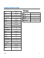
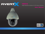
1
HD510 High Definition Outdoor IP PTZ Dome Camera User Manual HD510 High Definition Outdoor IP PTZ Dome Camera Operations Manual Manual Edition 33023AC – SEPTEMBER 2015 ©2015, AvertX All Rights Reserved No part of this document may be reproduced by any means, electronic or mechanical, for any purpose, except as expressed in the Software License Agreement. AVERTX shall not be liable for technical or editorial errors or omissions contained herein. The information in this document is subject to change without notice. The information in this publication is provided “as is” without warranty of any kind. The entire risk arising out of the use of this information remains with recipient. In no event shall AVERTX be liable for any direct, consequential, incidental, special, punitive, or other damages whatsoever (including without limitation, damages for loss of business profits, business interruption or loss of business information), even if AVERTX has been advised of the possibility of such damages or whether in an action, contract or tort, including negligence. This software and documentation are copyrighted. All other rights, including ownership of the software, are reserved to AvertX. AVERTX, and AvertX, are registered trademarks of AVERTX in the United States and elsewhere; Windows is a registered trademarks of Microsoft Corporation. All other brand and product names are trademarks or registered trademarks of the respective owners. The following words and symbols mark special messages throughout this guide: WARNING: Text set off in this manner indicates that failure to follow directions could result in bodily harm or loss of life. CAUTION: AVERTX 2 Text set off in this manner indicates that failure to follow directions could result in damage to equipment or loss of information. IMPORTANT SAFEGUARDS 1. Read Instructions Read all of the safety and operating instructions before using the product. 2. Retain Instructions Save these instructions for future reference. 3. Attachments / Accessories Do not use attachments or accessories unless recommended by the appliance manufacturer as they may cause hazards, damage product and void warranty. 4. 5. Installation Do not place or mount this product in or on an unstable or improperly supported location. Improperly installed product may fall, causing serious injury to a child or adult, and damage to the product. Use only with a mounting device recommended by the manufacturer, or sold with the product. To insure proper mounting, follow the manufacturer's instructions and use only mounting accessories recommended by manufacturer. Precautions Operating Before using, make sure power supply and others are properly connected. While operating, if any abnormal condition or malfunction is observed, stop using the camera immediately and then contact your local dealer. Handling Do not disassemble or tamper with parts inside the camera. Do not drop or subject the camera to shock and vibration as this can damage camera. Care must be taken when you clean the clear dome cover. Scratches and dust will ruin the image quality of your camera. Do not use strong or abrasive detergents when cleaning the camera body. Use a dry cloth to clean the camera when it is dirty. In case the dirt is hard to remove, use a mild detergent and wipe the camera gently. Power source This product should be operated only from the type of power source indicated on the marking label. Installation and Storage 33023AB Do not install the camera in areas of extreme temperatures in excess of the allowable range. (14°F~ 122°F / -10°C ~ 50°C) Avoid installing in humid or dusty places. The relative humidity must be below 90%. Avoid installing in places where radiation is present. Avoid installing in places where there are strong magnetic fields and electric signals. Avoid installing in places where the camera would be subject to strong vibrations. Never face the camera toward the sun. Do not aim at bright objects. Whether the camera is in use or not, never aim it at the sun or other extremely bright objects. Otherwise the camera may be smeared and damaged. 3 REGULATION This device complies with Part 15 of the FCC Rules. Operation is subject to the following two conditions: (1) this device may not cause harmful interference, and (2) this device must accept any interference received, including interference that may cause undesired operation. This symbol on the product or on its packaging indicates that this product shall not be treated as household waste in accordance with Directive 2002/96/EC. Instead it shall be handed over to the applicable collection point for the recycling of electrical and electronic equipment. By proper waste handling of this product you ensure that it has no negative consequences for the environment and human health, which could otherwise be caused if this product is thrown into the garbage bin. The recycling of materials will help to conserve natural resources. For more details information about recycling of this product, please contact your local city office, your household waste disposal service or the shop where you purchased the product. Compliance is evidenced by written declaration from our suppliers, assuring that any potential trace contamination levels of restricted substances are below the maximum level set by EU Directive 2002/95/EC, or are exempted due to their application. . 4 WARNING DANGEROUS HIGH VOLTAGES ARE PRESENT INSIDE THE ENCLOSURE. DO NOT OPEN THE CABINET. REFER SERVICING TO QUALIFIED PERSONNEL ONLY.CAUTION TABLE OF CONTENTS................................................................................................................................................................................................................... 5 INTRODUCTION .............................................................................................................................................................................................................................. 8 Overview .................................................................................................................................................................................................................. 8 Camera Default Settings ................................................................................................................................................................................... 8 Product Features ............................................................................................................................................................................................... 8 ONE: GETTING STARTED ............................................................................................................................................................................................................. 9 Box Contents .......................................................................................................................................................................................................... 10 Camera Box Contents ..................................................................................................................................................................................... 10 Wall Mount Accessory Box Contents .............................................................................................................................................................. 10 Camera Wire Connections .............................................................................................................................................................................. 11 Optional Power Supply .................................................................................................................................................................................... 11 Camera Overview ................................................................................................................................................................................................... 12 Camera Diagram ............................................................................................................................................................................................. 12 Dimensions...................................................................................................................................................................................................... 12 TWO: DEVICE SEARCH ............................................................................................................................................................................................................... 13 Using the Camera Finder ....................................................................................................................................................................................... 14 Finding IP Cameras ......................................................................................................................................................................................... 14 Changing the IP Address of a Camera ............................................................................................................................................................ 14 Administrator/User Privileges .......................................................................................................................................................................... 14 Default Username and Password ............................................................................................................................................................. 14 THREE: SETUP AND CONFIGURATION ..................................................................................................................................................................................... 15 Installing the camera .............................................................................................................................................................................................. 16 Installation Using Wall Mount .......................................................................................................................................................................... 16 Running Cables Inside the Wall ............................................................................................................................................................... 16 Running Cables on Wall Exterior ............................................................................................................................................................. 17 Attaching the Camera to Bracket ............................................................................................................................................................. 18 Network Connection ........................................................................................................................................................................................ 19 Waterproof the Cable Using the Conduit Gland ....................................................................................................................................... 19 Waterproof the Cable Using the Cable Gland .......................................................................................................................................... 21 Resetting the Camera ..................................................................................................................................................................................... 23 Recording to the microSD Card .............................................................................................................................................................................. 23 Digital Input / Output (optional) ........................................................................................................................................................................ 24 Connecting to the Camera ...................................................................................................................................................................................... 26 Connecting in a Web Browser ......................................................................................................................................................................... 26 Live View ................................................................................................................................................................................................................ 26 PTZ Camera Controls ............................................................................................................................................................................................. 27 Home Position ................................................................................................................................................................................................. 27 Command Protocol .......................................................................................................................................................................................... 27 Pan and Tilt ..................................................................................................................................................................................................... 27 Zoom Controls ................................................................................................................................................................................................. 28 Focusing the Camera ...................................................................................................................................................................................... 28 Preset Positions List ........................................................................................................................................................................................ 28 Set and Enable Tours ...................................................................................................................................................................................... 29 PTZ Scan Function .......................................................................................................................................................................................... 29 Camera Settings ..................................................................................................................................................................................................... 30 Viewer Tabs .................................................................................................................................................................................................... 30 Host ................................................................................................................................................................................................................. 31 Changing the Host Name and Camera Name .......................................................................................................................................... 31 Changing the Language ........................................................................................................................................................................... 31 Date and Time ................................................................................................................................................................................................. 31 Setting the Date and Time ........................................................................................................................................................................ 31 Network ........................................................................................................................................................................................................... 32 IP Address Filtering .................................................................................................................................................................................. 32 Port Managing .......................................................................................................................................................................................... 32 HTTPS ..................................................................................................................................................................................................... 32 IEEE 802.1X ............................................................................................................................................................................................. 33 SNMP Setting ........................................................................................................................................................................................... 33 RTP .......................................................................................................................................................................................................... 33 Network .................................................................................................................................................................................................... 34 IP SETTINGS .................................................................................................................................................................................................. 35 Connection Type ...................................................................................................................................................................................... 35 DNS.......................................................................................................................................................................................................... 35 Video and Audio .............................................................................................................................................................................................. 36 Camera Options ....................................................................................................................................................................................... 36 6 Video ........................................................................................................................................................................................................ 36 Audio (requires additional equipment) ...................................................................................................................................................... 38 Event ............................................................................................................................................................................................................... 39 Event Server ............................................................................................................................................................................................ 39 Event Configuration .................................................................................................................................................................................. 39 Event List ................................................................................................................................................................................................. 40 Manual Event ........................................................................................................................................................................................... 41 Local Storage Management ............................................................................................................................................................................ 42 Status ....................................................................................................................................................................................................... 42 Utilities...................................................................................................................................................................................................... 42 System ............................................................................................................................................................................................................ 43 User Account ............................................................................................................................................................................................ 43 System Info .............................................................................................................................................................................................. 43 Factory Default ......................................................................................................................................................................................... 43 Firmware Upload ...................................................................................................................................................................................... 43 Save and Reboot ..................................................................................................................................................................................... 43 Logout ............................................................................................................................................................................................................. 43 FOUR: SPECIFICATIONS ............................................................................................................................................................................................................. 44 Camera Specifications ............................................................................................................................................................................................ 45 PTZ Detail ....................................................................................................................................................................................................... 45 33023AB 7 8 2MP 1080p Video 30x Optical Zoom Lens The HD510 PTZ Camera is capable of providing real time streaming video with smooth image quality. The HD510 offers quad streaming and can be used in a variety of installations including shops, stores, home, banks, factories and for building surveillance. Pan/Tilt/Zoom Control 360° Endless Rotation Wide Dynamic Range (WDR) With Power over Ethernet Plus (PoE +), the need for separate power lines is eliminated and cabling and installation costs can be significantly reduced. The light weight, small size, and large degree of rotation of the camera facilitates quick and simple installation on either the ceiling or walls of structures or vehicles. Day/Night (ICR) Micro SD Support Weather-proof (IP66) Integrated Heater IP Address Dynamic Host Configuration Protocol (IP address assigned by router) Username admin Password 1234 Management Port 80 Streaming Port (RTSP) 7070 Box Contents Camera Overview 33023AB 9 Before proceeding, please check that the box contains the items listed here. If any item is missing or has defects, DO NOT install or operate the product and contact your dealer for assistance. Wall Mount HD510 PTZ Camera Safety Strap Cable Gland & Conduit Gland Mounting Screws Software & Documents CD 10 Set Screw & Washer Power Adapter Mount Back Plate Video and Power Connection Power Connection (Optional) (Required) 33023AB The HD510 PTZ Camera includes an optional power supply. The HD510 is PoE (Power Over Ethernet) capable. The power supply is only needed for Ethernet cable runs of over 300 feet or if your NVR does not supply sufficient power (25.44 watts needed). Digital In/Out Audio In/Out (Optional) (Optional) 11 Before installing or connecting the dome camera, please refer to this section and complete preparations for dome setup and all switch settings. Mounting Bracket Safety Strap Screw Height: 10.9” (including wall mount bracket) Camera Dome Cover Lens Width: 7.9” 12 Using the Camera Finder 33023AB 13 Use the included IP Utility software to easily find your network cameras for initial setup. The IP Utility software is included on the software CD with your camera. The HD510 PTZ camera is DHCP compatible, meaning it can be assigned an IP address from a DHCP server automatically when connected to the network for the first time. This is ideal for setup that requires an indirect connection between the camera and recorder, usually for network security or installation considerations. Use the IP Utility software to configure your IP cameras if you are not using Plug N’ Play as a direct connection to your AvertX recorder. 1. Open the Software CD on your PC and install the IP Utility. 2. In the IP Utility, identify your IP camera(s) by IP address or model. Note Only cameras connected to the network will show up in the IP Utility camera list. 1. Click the check box next to the selected camera, and then click Change Network Address to modify the IP address of the camera. 2. In the pop-up window, select Static IP Address, and then modify the Starting IP Address. 3. Click Apply. 4. Click Refresh in the IP Utility to view the IP camera’s new IP address. Tip The camera is set to DHCP by default. The IP addres is assigned by the router. Note You can check the box next to multiple cameras to change the IP addresses sequencially. The Administrator account has the authority to configure the IP camera and authorize users’ access to the camera. The User accounts have access to the camera with limited authority. The username and password are case sensitive. It is strongly recommended that the password be changed after the initial setup to prevent unauthorized access. Username – admin Password – 1234 The Mighty Squirrel Contr ol 14 Installing the Camera Connecting to the Camera Camera Settings 33023AB 15 1. If running cables through the wall behind the wall bracket, drill a ½” hole in the wall, and then pull all cabling through the upper hole in the wall bracket and connect the cables from the wall to the cables from the camera. 2. Screw the wall bracket to the wall using screws appropriate for your installation situation. The HD510 PTZ camera can be mounted in a number of ways. Depending on the situation, you may need to install the mounting solution first before connecting the cables, or the cables may need to be connected before installing the mounting solution. Below are basic installation details for the standard supplied mounting solution. The standard supplied wall mounting solution offers waterproof protection for both the camera and cables. The wall mount has a lower hole that can be used for an outdoor waterproof cable situation, or the cables can be housed inside the wall behind the wall mounting solution. To determine the appropriate cable setup, see the Network Connection section. Note 16 If cables must be run outdoors, instead of within the wall, the ideal waterproof protection is running the cables through conduit. 3. 1. If running cables outdoors using a waterproof solution such as conduit, pull all cables through the upper hole in the wall bracket, and then back out the lower hole of the wall bracket. 2. Screw the wall bracket to the wall using the screws appropriate for your installation situation, 33023AB Pull the cables through the conduit, and then push the conduit into the lower hole of the wall mount bracket. 17 18 1. Align the groove in the camera mount tube with the lock on the inside of the upper hole on the wall bracket. 2. Twist the camera mount tube into the wall mount bracket until the camera locks into place. 3. Using the set screw provided, screw the camera mount tube to the wall mount bracket. 4. Attach the safety strap to the camera and the wall bracket. 2. Insert the Ethernet cable through the conduit. Then insert the conduit through the clamping nut. 3. Slide the sealing rubber over the Ethernet and attach the sealing rubber to the end of the conduit. Two waterproof cable connection solutions are offered with the HD510 PTZ camera. If the cables run from the ceiling or wall into the camera, then the connection can be considered waterproof. If the camera is mounted in a way that exposes the cables, then it is recommended to waterproof the cables using the included connection glands, along with conduit or exterior grade Ethernet cable and waterproof tape, which are NOT included. For waterproof cable using the conduit gland, you will need: Conduit gland (included) Gland rubber ring (included) ½” Flexible conduit (not included) Waterproof tape (not included) 1. Disassemble the cable gland. Gland Body Clamping Nut Sealing Rubber 4. 33023AB Attach one rubber ring (included) on the gland body. 19 5. Attach the gland body to the Ethernet port of the camera. 6. Connect the Ethernet cable to the Ethernet port of the camera. 7. Insert the sealing rubber into the conduit gland body. 8. Tightly attach the clamping nut to the conduit gland body. 9. Arrange all unused camera cables and wrap them in waterproof tape. Camera Ethernet connection Note 20 Ensure the rubber ring is completely aligned and flat on the gland body to prevent water leakage. Note Different applications and installation environments require different types of waterproof methods that may not be covered in this manual. Check your installation environment and adapt a suitable waterproof mehod. Note If the camera is installed outdoors and the bundled power adapter is used, be sure to protect if from different environmental factors. It is reccommended to place the power adapter indoors or housed inside a junction box. 5. Attach the gland body to the Ethernet port of the camera. For waterproof cable using the cable gland, you will need: Cable gland (included) Gland rubber ring (included) Exterior grade Ethernet cable (not included) Waterproof tape (not included) 1. Disassemble the conduit gland. Gland GlandBody Body Clamping Nut Camera Ethernet connection Sealing Rubber 2. Slide the clamping nut onto the Ethernet cable. 3. Insert the Ethernet cable through the sealing rubber. 4. Attach one rubber ring (included) on the gland body. 33023AB 21 6. Connect the Ethernet connector to the Ethernet port of the camera. 7. Insert the sealing rubber into the gland body. 8. 22 Tightly attach the clamping nut to the cable gland body. Note Different applications and installation environments require different types of waterproof methods that may not be covered in this manual. Check your installation environment and adapt a suitable waterproof mehod. Note If the camera is installed outdoors and the bundled power adapter is used, be sure to protect if from different environmental factors. It is reccommended to place the power adapter indoors or housed inside a junction box. If it is necessary to reset the camera to the factory default settings, hold down the Reset button (see Camera Overview) for 30 seconds. This will return all settings, including network setup, to the factory default. The IP address of the camera will be reassigned by the router. Your camera includes a microSD card slot (compatible with cards up to 32GB), which can be used for emergency video backup. The microSD card is not included. You must remove the clear dome cover of the camera to access the microSD card slot. Note The camera dome cover must be removed to access the microSD card and the reset button. See the Local Storage Management section on page 39 for more information about recording to the microSD card. 33023AB microSD Slot Reset Button 23 You can connect up to 4 digital input devices to the camera to trigger events. There are also 2 digital outputs to allow you to trigger notifications on events. 24 The camera comes with audio input / output jacks to connect a microphone or speaker to the camera. The audio jacks are covered with a rubber protection. If using an audio input device, such as a microphone with a built-in amplifier, connect the device to the Audio Input jack (RED) of the camera. If using an audio output device, such as a speaker, connect the device to the Audio Output jack (GREEN) jack of the camera. Audio Output Jack (Green) If the camera is installed outdoors, be sure to wrap the audio connectors with waterproof tape (can be purchased in hardware stores). NOTE: Make sure that the connected audio input device has a amplifier. Connecting an ordinary microphone will will result in inaudible recording. If the audio connectors will not be used, leave the rubber caps on to avoid water and dust from entering the connectors. Audio Input Jack (Red) . 33023AB 25 Live View: displays the live camera view Settings: displays camera configuration functions 1. 2. Type the IP address of the camera in a web browser. --OR-Use the included IP Utility software and locate the camera on the IP Finder list, then double-click the camera to open the Viewer software in your web browser, or right-click and select Browse. Streams: show stream 1 or 2 in the live view Full Screen: enlarge the live camera view to full screen Log in to the camera with the appropriate User Name and Password. Note The default User name is admin and the default Password is1234. The username and password are case sensitive. Snapshot: take a Snapshot, these JPGS are saved in the Pictures folder Audio: speak to the camera (requires additional equipment) When connecting to the camera in a web browser, the Live View screen is the default home screen. From this screen you can view and control live video. Zoom Controls: enlarge and reduce the video size digitally PTZ Controls: this will open the PTZ camera control panel Note If you are accessing the camera through the recorder, your live screen may be empty because the default port for the camera is different. DO Ports: select a DO port, 1 or 2 DO Port Level: manually trigger a DO device 26 Home Position Use the Pan Tilt controls to navigate the camera to the desired position and then click the Apply button to designate the camera’s current position as the Home Position. Command Protocol Pan & Tilt controls Directional Controls Movement Speed If the camera needs to be used with third party devices, the camera supports Serial Hex Command as a low level PT command set. Select the PTZ Vender/ Protocol to use and the address. Otherwise, leave default settings. Use the Directional Controls to pan/tilt the PTZ camera. Auto Pan/Tilt Speed: when enabled, the camera will automatically set the pan/tilt speed according to the zoom ration and selected pan/tilt speed while also maintaining clarify and quality of image. Zoom Controls Movement Speed: when auto pan/tilt speed is disabled, the camera will follow the value set in the Pan/Tilt Speed field. Higher numbers represent faster speeds. Focus Controls Preset Positions List 33023AB 27 5. To create more preset positions, repeat steps 1-4 as needed. To zoom continuously: 1. Select a Speed, with higher numbers representing faster speeds. 2. Click and hold the Continuous Zooming buttons for zooming in or out. To zoom in steps: 1. Enter the desired Step Size. 2. Click the Stepped Zooming buttons one click at a time to zoom in by the set Step Size per click. After adjusting the camera, it is recommended to adjust the Focus Control for optimal video quality. Auto Refocus after Zoom: this option will automatically adjust the camera focus after zooming. Manual: select this option to manually adjust the camera focus. This option is useful if the autofocus option is not the desired position. Preset positions are user defined camera positions that can be zoomed in on. A series of these points can be grouped together as a Tour. To create a present position: 28 1. Click the Edit icon wish to configure. 2. Type a Name for the position. 3. Pan, tilt, and zoom on the area until you have the desired camera angle and focus. 4. Once completed, click the Edit icon complete the preset position configuration. next to the position number you again to Note The Go-to-Preset icon will take you to the preset position once it has been designated. The Delete icon the preset position. will delete The Scan function moves the camera from one predefined point to another by scanning the view horizontally without losing focus. Unlike preset tours, where the camera moves quickly and can focus independently depending on the preset position, scan keeps the entire view in focus and moves at a steady, consistent pace. To configure the PTZ Scan Function: 1. Click the Edit icon next to scan point 1 to set the starting scan point. 2. Pan and tilt the area that you will set as scan point 1. 3. Click the Edit icon again to close and complete scan point 1. 4. Repeat steps 1-3 for scan point 2. 5. Set the preferred Scan Speed and Scan Direction. Note The Delete icon will delete the scan point configuration and allow you to set new scan points. After preset positions have been created, they can be grouped into a Preset Tour. To configure a Preset Tour: 1. Click Edit Tour in the Touring Control tab of the PTZ menu. 2. Select a preset position using the drop-down menu. 3. Designate the duration (in seconds) of that preset position. 4. Select a pan/tilt speed from the drop-down menu, and then click the Add icon . Add preset positions to the tour as needed. To change the sequence of the preset positions, use the directional icons points up or down the list. to move 5. When you are finished setting the preset positions for the tour, click Save. 6. Using the Touring Control drop-down menu, select the desired tour name to activate the tour. 33023AB 29 You can access the camera setup menu using an internet browser on your computer. The camera viewer software will install automatically the first time you connect to the camera. If your internet browser doesn’t install the viewer software, check the security settings or ActiveX controls and plug-in settings. If your internet browser asks for permission to install the plugin, you must allow ActiveX or QuickTime to install to continue the installation. Host – define the name of the camera and the preferred interface language. Date and Time – provides options for adjusting the time and date of the camera. Network – listing of network related functions, services, and protocols. IP Settings – define which devices (by the IP addresses) are allowed to connect to the camera. Video and Audio – control the video and audio functions of the camera. Event – configure events, triggers, and responses. System – full information about the camera, settings, status, and log. Logout – log out of the IP device. 30 Host options include the Host Name, Language options, and the Camera Name that will be displayed to identify the channel. 1. Click within the text box you wish to modify. 2. Type the new desired name. 3. Click Apply. SNTP/NTP Server – configure the settings by pulling date and time information from a reliable provider. 1. Click the Language drop down menu 2. Select a language, and then click Apply. 3. The browser will refresh, and then display the selected language. 33023AB Set Manually –configure the settings manually using the Date and Time drop-down menus. Daylight Saving – for countries with Daylight Savings policy, there are two ways to define the start time: by week in the month or by exact date in the month. 31 Note If you wish restrict or allow specific IP addresses from accessing the camera, you can use the IP address filter. You can Block or Allow IP addresses. To change the default port settings for your camera: 1. Click in the appropriate text box for the port number you wish to change. 2. Type the new port number. 3. Click Apply. Note To restrict or allow specific IP addresses to access your camera: 1. Check the Enabled check box. 2. Using the drop-down menu, select Blocked or Allowed. 3. Type in IP address or Network that you wish to block/allow access to your camera. 4. Check the Enabled check box next to the address. Note 5. Note You can have IP addresses or Networks on the list, but not enabled. The Enabled check box must be checked in order to activate either blocking or allowing that address. The Reset button will change the port numbers back to the numbers established before the Apply button was clicked. HTTPS protocol is used to create a secure channel over an insecure network in order to protect data. HTTPS does this by using certificates to verify that the data is accurate. Certificate Signing Request (CSR): users have a signed certificate from a Certification Authority (CA). Self-Signed Certificate: user has a certificate created or issued by the user himself. Click Apply. The Reset button will erase all of the IP and network addresses and return the list to default, with no addresses and no Enabled check boxes checked. Port Managing allows you to modify the default port settings for the camera. 32 Some settings may require a Save and Reboot after applying the changes in order to activate the changes on the camera. You will be prompted after applying a change if a Save and Reboot is needed. 1. Click Create or Create Self-Signed Certificate to configure settings. 2. Enter the appropriate information in the pop-up configuration window. 3. Click Create. Note After the creation of a certificate, you will be prompted to Save and Reboot to apply the settings. IEEE 802.1X is an IEEE standard for port-based Network Access Control. This requires network port devices to provide verification before being allowed access to a protected network, usually in the form of a username and password. 1. To enable IEEE802.1X, check the Enabled check box. 2. Designate an EAPOL Version. 3. Enter the desired Username and Password that will be used for verified access to the network. 4. Upload CA or User Certificate, and User Private Key from the RADIUS server. 5. Click Apply. Note After the configuration of IEEE 802.1X, you will be prompted to Save and Reboot to apply the settings. SNMP Trap Usage: SNMP trap enables notification from devices. Notifications will be sent on cold start, warm start, and authentication failure. If RTP is enabled, then account name and password authentication will be required for RTP streaming. Enabling RTP sends an additional B2 frame to every video frame, containing information such as motion detection, digital input and output levels, frame counter, resolution, timestamp, and more. To modify RTP settings: 1. Check the Enabled check box. 2. Modify settings appropriately. 3. Click Apply. SNMP provides easy management of network devices. Features of SNMP include monitoring device uptime, system detail description, collection of interface information, and measuring network interface throughput. To modify SNMP settings: 1. Check the Enabled check box. 2. Modify settings appropriately. 3. Click Apply. SNMP V1 / V2: uses “Community” name as password to authenticate identity. “Read Community” is the password for server to get information from devices. “Write Community” is the password for server to edit values on devices. SNMP V3: uses account/password for authentication. “Security Name”: is the account name to be used with your “Password” The default secuty name is “public.” 33023AB 33 Network allows you to manage default protocols for your camera. These protocols can be enabled or disabled and in some instances, the protocol can be given a specific name for easy identification. Universal PlugNPlay is a zero-configuration networking protocol that allows network devices to establish functional network connections for data sharing and communication. UPnP is responsible for allowing devices to dynamically join a network, obtain an IP address, and communicate with other network devices. Note Disabling UPnP will require a manual configuration of the camera. Bonjour is Apple’s implementation of zero-configuration networking, allowing network devices to establish functional network connections for data sharing and communication. This software is mainly used on OS X and iOS network devices. ONVIF protocol allows for integration between devices, regardless of manufacturer, based on a global standard for the interface of IP-based security products. Note Type of Service provides 4 options to define the priorities of how the date from the camera is handled by routers that support ToS. These settings include: normal service, minimize delay, maximize throughput, and maximize reliability. Click Apply to save changes made to ToS Priority. 34 Disabling ONVIF could disrupt the communication between devices from different manufacturers. DNS allows the setup of a Domain Name Service for the camera, which will connect to the DNS server when there is a situation requiring a domain name to send data to. The most common application for DNS is the ftp or e-mail server in the Event Handler section. You can establish both a primary and secondary DNS server address. Dynamic IP Address: Having a dynamic IP address means that the IP address for the camera can change depending on how the network router assigns addresses to network devices. By default, the camera is in Dynamic IP Address mode and will attempt to get an IP address from a DHCP server. If this attempt fails, the camera will automatically assign itself an IP address, listed under Static IP Address. Static IP Address: Having a static IP address means that the IP address for the camera will not change once assigned. PPPoE: In some rare cases, the camera may be connected over the Internet. The most effective way to do this is with Power over Ethernet, using an Ethernet cable to both power the camera and provide a network connection. To change the connection type: 1. Click the appropriate connection type. 2. If needed, designate the specific addresses. 3. Click Apply. 33023AB 35 The default video and audio settings are sufficient in most installation settings. This section provides detail on streaming, video quality, and audio configuration if settings need to be adjusted. Video allows you to modify detailed features of the camera, including Compression, Motion Detection, Day/Night, Image, Exposure/White Balance, and OSD/Privacy Mask. Camera options allow you to control the streams of the camera, including the Stream Mode and the number of Video Streams. To modify the camera streams: 36 1. Use the drop-down menus to select Stream Mode and the number of Video Streams. 2. Click Apply. This section allows the configuration of Stream 1 and 2. Compression reduces bandwidth and VMS storage consumption. Usually, Stream 1 is the best quality stream for NVR recording purposes, while Stream 2 is configured for basic quality in Live view of NVR. Motion detection is based on Stream 1, and by default, all regions are disabled. Up to three detection regions can be enabled, each with their own location, size, and sensitivity. To enable and configure motion detection: 1. In the Motion Detection tab, click Setup. 2. Check the Enabled check box to enable the desired Detection Regions. 3. Drag the detection square to the desired region in the camera view. 4. Drag the lower right corner of the detection square to change the size if needed. 5. Using the drop-down menu, se the sensitivity of the detection square. The lower the sensitivity, the more movement is permitted before triggering an event. This section allows for the configuration of day/night settings. The AvertX HD510 has three Day/Night Modes: Auto: the camera will automatically switch between day mode (color) and night mode (black and white) under certain exposure levels. This level is defined by the user in the Switch from Day mode to Night mode drop-down menu. Day: the camera stays in day (color) mode regardless of the exposure level. Night: the camera stays in night (black and white) mode regardless of the exposure level. To configure Auto Day/Night mode: 1. Select Auto in the Day/Night mode drop-down menu. 2. Use the Switch from Day mode to Night mode drop-down menu to select an exposure value that will switch the camera from one mode to another. --OR— Trigger threshold is an effective tool for quantifying how much movement and what speed of movement that will trigger an event. This is necessary in outdoor situations where insects or small animals may cause a motion detection trigger. Thresholds are based on pixel percentages. The default trigger threshold is 10% of pixels moving. Ideally, the trigger threshold is small enough to effectively sense human and vehicle motion, but ignores any smaller motion. Low threshold: 0-5%, will detect and trigger even minute movement. High threshold 5-100%, will detect and trigger only larger movement. Use the sliding scale to set the exposure value. This section allows for the configuration of certain parameters of a video frame. The default settings in this section are well suited to most environments and it is recommended that the default remain unchanged. This section allows you configure exposure settings, such as shutter, iris, and gain control, and white balance settings. The default settings in this section are well suited to most environments and it is recommended that the default remain unchanged. There are two profiles available for motion detection: Runtime MD Profile and Event MD Profile. These are independent groups that can have three separate regions per group. Having two separate profiles is most commonly used when motion detection needs are different between day and night. 33023AB 37 On-Screen Display is used to add text to the upper or lower left corner of video. This can be used for branding or authentication purposes. Primarily, the text is kept as small as possible and is not resizable. The text is kept as small as possible as not to block any video. To add an OSD to your video: 1. Check the Enabled check box next to the desired OSD region. 2. Use the drop-down menu to choose a color for the text. 3. Set the transparency. This dictates the color saturation for the OSD and how well you can see the video behind the text. A lower transparency will be easier to see through. 4. Choose a position for the OSD to appear. The AvertX HD510 PTZ camera supports audio features. 5. Type the desired text to appear as the OSD. Audio In: when enabled, incoming audio is activated. When disabled, incoming audio is turned off. Note See the Apendix for a list of special characters that can be used in the text box to give special meanings, such as Date and Time as configured by the camera, and special characters. Privacy masks are used to intentionally block specific areas of video, most commonly used to hide faces. You can have up to four regions of privacy masks, though they will all be the same color. The privacy mask is dynamic. When the camera pans, the region that was originally covered will remain covered. To set up privacy masks: 1. Check the Enabled check box next to Region 1. Note 38 Although up to four regions can be enabled, they must be enable in sequencial order. 2. Check the Setup box. 3. Drag and resize the privacy mask as needed. The upper bar containing the region number is used to move the privacy mask while the box at the lower right corner of the privacy mask is used to resize. 4. Return to live view and ensure the privacy mask is correct. Audio Out: can be adjusted from a scale of 0-100, effect the volume level of the speakers connected to the camera. Audio Format: compression format for audio. HTTP Server: these servers can be programmed to perform a large variety of actions based on the input. The AvertX HD510 has an Event Handler, or set of protocols that determine how to deal with IP devices and their response to situations, including both triggers and responses. The AvertX HD510 can interact with numerous external devices to activate triggers and prompt responses. Click the Expand icon To configure a HTTP server: 1. Enable the HTTP server and choose the proper authentication type. 2. Enter the appropriate information. 3. Click Apply. next to the Event list to expand the options. The event servers define which devices the camera can interact with, most commonly being other devices on the network. The event servers are classified as FTP, SMTP and HTTP servers. FTP Server: these servers receive snapshot or video uploads that are issued as part of the response from event handlers. To set up a FTP server, enter the necessary information and click Apply. The event configuration section defines the responses to be performed when an event is triggered. For most type of responses, you can create several different preset responses, then mix and match in the event rules. Configurable responses are classified as Digital I/O ports, Notification messages, Upload Video/Snapshot and Audio, and Send URL Commands. Click the Edit button next to the category that you want to configure. SMTP Server: these servers send email upon request from the camera. The email can be subject and text email or include a snapshot / video. You can have a primary and secondary SMTP server. To configure a SMTP server: 1. Enable the SMTP account and choose the proper authentication type. 2. Enter the appropriate information. 3. Click Apply. 33023AB 39 Digital I/O Ports are used to connect digital input (DI) and digital output (DO) devices. Typically, DI is a trigger device such as a switch or sensor. The DO is notified by the trigger and then performs a specific action, such as sounding an alarm. Your AvertX HD510 camera can send video recording/ snapshots to your chosen server upon event. If audio is enabled on the device, the uploaded video will also have audio. To configure the Digital Input Device: 1. Define the active level as 1 or 0 using the drop-down menu. An active level of 0 means the DI device is inactive unless triggered. 2. Specify an Interval. The Inverted is the duration of time when the trigger remains in active mode before returning to active level 0. To configure the Digital Output Device: 1. Define the active level and response interval as with the DI device. The default active level for DO devices is 1, which means the DO device will respond once triggered. 2. Click Apply when you are finished configuring both DI and DO devices. There are a maximum of 10 Event rules which are shown in abbreviated form in the Event List. To configure a new event: Notification messages can be sent to an email or a HTTP server. You can configure up to three preset messages. 1. Click the desired ID number. 2. Check the Enabled check box. To configure notification messages: Note You can still configure an event even if it is not enabled. The event configureation will be saved and can be enaled at a later time. 1. Check the Notification Message box to enable the message and then use the Send Message to drop-down menu to determine if sending the message to an email or a HTTP server. 2. Enter the appropriate information depending on which method you have chose. 3. Check the Active on check boxes for the desired week days the event will be active. 3. Click Apply. 4. Use the drop-down menus to chose a time and event duration. For example, a rule that allows motion detection trigger snapshot uploads to FTP would only take place after 19:00 each day for a 12 hour duration. Outside of this duration, this event will not take place. 40 There are several triggers that can cause events. These triggers include: DI: digital inputs, or external network devices that are connected to the camera. These include sensors or switches. Motion: if the camera senses motion detection. Video Loss: this is available for video servers only. When analog video is lost it will trigger an event. Switch to Night Mode: when the camera changes between day and night modes, an event can be triggered. Device Boot or Reboot: an event can be triggered when the camera boots or reboots. Storage: if storage space runs out or if writing to storage fails, or if the microSD card is suddenly removed from the camera. You can set any event rule as a manual event. The manual event will display in the live screen as the Trigger button, which can be clicked to trigger an event and response. To set a manual event: 1. Us the drop-down menu to select an Event Rule. 2. Click Apply. To configure triggers: 1. Use the drop-down menu to choose a Triggered by category. 2. If needed, choose a Region. 3. Designate a response to the event. 33023AB 41 Utilities manage local storage and include Mount, Format, and Scan. Inserting a memory card into the memory card slot will enable local storage management capabilities. This allows users to manage files saved on the memory card as well as define schedules and event rules for recording. When the storage media displays Mount, then microSD storage has been inserted into the camera, but the connection between the camera and the storage has not been established yet. The storage can be unmounted at a later time with the Unmount button. If local storage has not been formatted yet, the camera will not display the status of the storage. If local storage has been formatted, the capacity ratio will be displayed, along with the File System. Use the Scan utility to check the health of the storage. If the scan fails, then the microSD card is not recognized by the camera. File Management is available only when the microSD card is mounted in the camera. When a microSD card is mounted in the camera, Stream 1 is automatically recorded to the microSD card. 42 Select which option best fits your needs, and then click Apply. The System section provides the list of functions that help manage the camera. This section allows you to remote upgrade, or in some cases downgrade, the camera firmware. Upgrading is most commonly done to attain new functions or fix existing issues. Downgrading may be necessary when attempting to integrate with other products. To download new firmware: 1. Download the firmware file form xxxxxxxx.com. The file will have the extension “.upg.” 2. In the Firmware Upload section, click Apply. 3. Click Browse to search for the desired firmware file, and then click Apply to start the upload. Upon completion of upgrade, the system will reboot. User Account allows you to change the account name or password of the Administrator account that has full access to the camera, create up to 10 common users that only have access for live view and the PTZ control, and to enable/disable the option for live view by users who are not logged in. The System Info provides the full information about camera status, settings, and log. This information is for viewing purposes and may assist you with camera configuration or maintenance. The Save and Reboot section allows you to save settings and reboot the camera remotely. This is an important function because some changes will not take effect until a Save and Reboot has been completed. To Save and Reboot, click Apply. It is recommended that you log out of your AvertX HD510 PTZ camera when you have finished all of the desired tasks. This will prevent unauthorized use of the camera. This section allows you to return the camera to default settings, and also provide the option of preserving the network setting and HTTP/HTTPS port. 33023AB 43 44 Model HD510 PTZ Resolution 1080p (2MP) IP Rating Wide Dynamic Range Day / Night IP66 Spectrum Vision Wide Dynamic Range True Day/Night Focal Length 4.3~129 mm FOV 66.4°~2.61° Iris Control Audio Backlight Compensation Yes Privacy Mask Yes Power Consumption Input Voltage Weight Dimensions Relay Outputs 2 Tilt/rotation Image Stabilization Pan: 0°-360° endless; Tilt: -20°-200° Yes No H.264 / MJPEG Heater 4 True Day/Night Compression Operating Temperature Alarm Inputs 2 way (Requires additional equipment) Yes IR LED 256 Preset positions, 10 Preset tours F1.6~F5.0 auto-iris Auto Gain Control Day / Night Presets -40°F ~ 122°F (-40°C ~ 50°C ) Yes 25.44W (PoE+) / 31.5W (24vAC) PoE+ / 24wAC 5.7 lbs (2.58 kg) H: 10.9” x W: 7.9” (276 mm x 200 mm) 33023AB 45 ww.avertx.com 1-855-2AVERTX © 2015 AvertX All rights reserved. No part of this publication may be reproduced by any means without written permission from AvertX. The information in this publication is believed to be accurate in all respects. However, AvertX cannot assume responsibility for any consequences resulting from the use thereof. The information contained herein is subject to change without notice. Revisions or new editions to this publication may be issued to incorporate such changes. 46