1
GE Consumer & Industrial
Power Protection
MPACT-PLUS
Trip Unit | Auslöseeinheit
MPRO 27 & MPRO 50
Installation, Operation and Maintenance Manual
Installations-, Betriebs- und Wartungs-Handbuch
GE imagination at work
MPACT-PLUS
Trip unit MPRO 27 & MPRO 50
Caution! Important Requirements!
Achtung! Wichtige Forderungen!
WARNING
Safety Precautions
It is recommended that the following precautions be included in
any procedural instructions to personnel concerned with the
handling, operation or maintenance of 'MPACT-PLUS' circuit
breakers.
During operation this circuit breaker is connected to dangerous
voltages. When the circuit breaker is switching high currents,
especially short-circuit currents, hot and ionized gas may be
emitted.
Only qualified personnel are allowed to install, commission,
maintain or modify this device in accordance with relevant safety
requirements. The circuit breaker must be equipped with a
proper fixed cover or installed in a suitable enclosure or panel
board to allow adequate safety clearance.
Before detailed inspection or any maintenance work is
commenced:
-- All electrical supplies to the circuit breaker should be switched
off.
-- The circuit breaker should be tripped to the OFF position and
the closing springs discharged. This releases stored energy in the
spring mechanism, thus eliminating risk of injury due to
unintentional tripping or closing during inspection and
maintenance.
While handling the breaker, care should be taken to avoid risk of
injury from moving parts.
-- The circuit breaker and its accessories must always be used
within their designated ratings.
-- Use of the breaker handling truck is recommended when
removing the breaker from its cassette.
Non compliance with this warning could result in equipment
damage, severe personnel injury or even life lost.
Lesen Sie bitte diese Betriebsanweisung und bewahren Sie
sie bitte griffbereit auf.
WARNUNG
Sicherheitsmassnahmen
Es wird empfohlen, dass die folgenden Maßnahmen bei der
Handhabung, dem Betrieb und der Wartung des 'MPACT-PLUS'Leistungsschalters durch das Fachpersonal unbedingt eingehalten
werden.
Im Einsatz ist dieser Leistungsschalter an gefährliche Spannungen
angeschlossen. Wenn der Schalter hohe Ströme, insbesondere
Kurzschlussströme abschaltet, treten heiße Gase auf der Oberseite
des Schalter aus.
Nur qualifiziertem Personal ist es gestattet zu installieren, in Betrieb
zunehmen, instandzusetzen oder dieses Gerät in Übereinstimmung
mit den einschlägigen Sicherheitsanforderungen zu ändern. Der
Schalter muss mit einer festen Abdeckung versehen sein oder in
ein geeignetes Gehäuse oder Schaltschrank eingebaut sein, um
einen ausreichenden Sicherheitsabstand zu gewährleisten.
Vor Beginn einer Inspektion oder Wartung ist zu beachten:
-- Spannungsfreiheit des Leistungsschalters herstellen.
-- Der Leistungsschalter ist auszuschalten und der
Federkraftspeicher muss entspannt sein, um das Risiko von
Verletzungen durch versehentliches Auslösen oder Schließen
während der Arbeiten am Schalter auszuschließen.
Während der Arbeiten am Schalter ist sorgfältig auf das
Verletzungsrisiko durch bewegliche Teile zu achten.
Die Verwendung einer optional erhältlichen Kabel-/
Sammelschienen-Erdungsvorrichtung ist empfehlenswert für
zusätzliche Sicherheit während der Wartungsarbeiten.
Leistungsschalter und Zubehör dürfen nur innerhalb ihrer
vorgesehenen Anwendungsgebiete eingesetzt werden. Die
Benutzung des speziell für den MPACT-PLUS angebotenen
Hubwagens ist empfehlenswert, um den Leistungsschalter aus
dem Einschubträger zu heben.
Die Nichtbeachtung dieser Warnhinweise kann die Ausrüstung
beschädigen, gesundheitliche Schäden verursachen oder zum Tod
führen.
APPENDIX
SCREEN MODE
OPERATION
PROTECTION
GENERAL
INTRO
Read this manual and please retain for future use.
WARRANTY
This document is based on information available at the time of its
publication.
While efforts have been made to ensure accuracy, the information
contained herein does not cover all details or variations in hardware and
software, nor does it provide for every possible contingency in connection
with installation, operation, and maintenance.
Features may be described herein that are not present in all hardware and
software systems.
GE Electrical Distribution & Control assumes no obligation of notice to
holders of this document with respect to changes subsequently made.
GE Electrical Distribution & Control makes no representation or warranty,
expressed, implied, or statutory, with respect to, and assumes no
responsibility for the accuracy, completeness, sufficiency, or usefulness of
the information contained herein.
No warrantees of merchantability or fitness for purpose shall apply.
Contact your local sales office if further information is required concerning
any aspect of MPACT-PLUS circuit breaker operation or maintenance.
GARANTIE
Dieses Dokument basiert auf die zum Zeitpunkt der Veröffentlichung
verfügbaren Informationen.
Es wurden alle Anstrengungen zur Vollständigkeit des Handbuchs
unternommen, trotzdem kann die hierin enthaltene Information sich nicht
auf alle Details oder Variationen in Hard- und Software oder auf alle im
Zusammenhang mit Installation, Betrieb und Wartung auftretenden
Möglichkeiten beziehen.
Außerdem können hier Funktionen beschrieben sein, die nicht in dem
vorliegenden Hard- oder Software-System vorhanden sind.
GE Electrical Distribution & Control übernimmt keine Verpflichtung zur
Mitteilung an die Inhaber dieses Dokuments in Bezug auf Veränderungen.
GE Electrical Distribution & Control macht keine Zusicherungen oder
Garantien und übernimmt keine Verantwortung für die Richtigkeit,
Vollständigkeit oder Nützlichkeit der hierin enthaltenen Informationen.
Es gibt keine Gewährleistungen der Marktgängigkeit oder Eignung für einen
bestimmten Zweck.
Wenden Sie sich bitte an Ihr lokales Verkaufsbüro vor Ort, falls Sie weitere
Informationen zu Aspekten des MPACT-PLUS-Leistungsschalter in Betrieb
oder Wartung benötigen.
MPACT-PLUS
Installation, Operation and Maintenance Manual
Installations-, Betriebs- und Wartungshandbuch
HAZARD CATEGORIES
The following important highlighted information appears throughout this
document to warn of potential hazards or to call attention to information
that clarifies a procedure.
Carefully read all instructions and become familiar with the devices before
trying to install, operate, service or maintain this equipment.
GEFÄHRDUNGSKATEGORIEN
Die folgenden wichtigen, hervorgehoben Informationen in diesem
Dokument warnen vor möglichen Gefahren oder machen auf besondere
Verfahrenweisen aufmerksam.
Lesen Sie alle Anweisungen aufmerksam durch und machen Sie sich mit
dem Gerät vertraut, bevor Sie versuchen es zu installieren, zu betreiben
oder Service- und Wartungsarbeiten an dieser Ausrüstung vorzunehmen.
1.0
INTRO
TRIP UNIT
DANGER | GEFAHR
Indicates a hazardous situation which, if not avoided, could result in
death or serious injury.
CAUTION: Failure to comply with these instructions may result in product
damage.
NOTICE: An aid meant to assist the user in performing the set task. Please
retain for future use.
Zeigt an, dass eine vermeidbare, gefährliche Situation entstehen kann,
die zum Tod oder zu schweren Verletzungen führen kann.
VORSICHT: Die Nichteinhaltung dieser Anweisungen kann zu Schäden
am Produkt führen.
HINWEIS: Zeigt wichtige Informationen zur Hilfe und Klarstellung der
Angaben.
MPACT-PLUS Circuit Breaker Fitting
M-PACT PLUS Leistungsschalter Befestigung
Install the switch in a dry, dust-free, non-corrosive, room, with temperature,
height and humidity in compliance with standard IEC 947-1.For installations
in special rooms or rooms which exceed the limits laid down by the
standard contact GE Consumer & Industrial.
Fixed type
Before connecting the main and auxiliary conductors of the circuit breaker
and its accessories, as auxiliary switches and releases, care is to be taken
that all conductors, connectors and terminals are not energized.
Drawout type
Normally, drawout type circuit breakers will be delivered already mounted
in cassettes. Remove the breaker from its cassette using procedures
described in the MPACT-PLUS Circuit Breaker manual. Position the cassette
as required in the switchboard.
Note: The cassette may be lifted by hand but, if a handling truck or other
lifting gear is employed, all four of the lifting holes provided at front and
rear of the cassette should be used.
Position cassette in place and connect incoming and outgoing
cables/busbars. When connecting busbars ensure there is minimal
deflection/stress to the back of the cassette. Fix the cassette using 4 off M8
bolts to 25Nm at front and rear fixing points. Note, the cassette base before
and after fixing must be flat and the frame square.
Check that the safety shutters move freely after the fixing bolts have been
fully tightened.
An Earthing point is provided on the right hand side of each cassette
(viewed from front).
Der Leistungsschalter soll in eine trockene, staubfreie, nicht korrosive
Atmosphäre eingebaut werden, die des weiteren bezüglich Temperatur,
Höhe und Luftfeuchtigkeit den Richtlinien des IEC Standards IEC 947-1
entspricht. Für spezielle Anwendungen, die außerhalb der
Standarddefinitionen liegen, bitte mit uns Rücksprache halten.
Festeinbau Schalter
Vor dem Anschluss des Schalters unbedingt Spannungsfreiheit
sicherstellen. Auch für die Hilfsspannungskreise.
Ausfahrtechnik
Normaler Weise werden die Schalter für die Ausfahrtechnik zusammen mit
der Ausfahrtechnik geliefert. Zum Einbau des Einschubträgers muss
zunächst der Schalter entfernt werden (Siehe im MPACT-Handbuch).
Jetzt werden zunächst die Anschlüsse an die Sammelschienen oder Kabel
vorgenommen, dabei ist darauf zu achten, dass keine dauerhaften Zug-,
Druck- und Seitenkräfte auf den Einschubträger wirken.
Nach dem Anschluss der Hauptstrombahnen wird der Einschubträger mit
M8 Schrauben an den hinteren und vorderen Befestigungslöchern
befestigt. Diese werden dann mit 25Nm angezogen. Es ist darauf zu achten
das der Einschubträgen nach der Montage keine Verformungen aufweist
und die rechtwinklige Form weiter gegeben ist.
Wenn die Montage abgeschlossen ist, muss die freie Bewegung der
Berührungsschutzabdeckungen überprüft werden.
Zur Erdung ist der Einschubträger auf der rechten Seite (von Vorne gesehen)
mit einem Erdungspunkt versehen.
MPACT-PLUS Circuit Breaker Operation
MPACT-PLUS Leistungsschalter Betrieb
Closing procedure
Pull the charging handle out and down to charge the closing springs
(requires approximately 7-8 movements of the handle to fully charge).
If a motorized spring charging unit is fitted, the springs will be automatically
charged as soon as the motor is energized. Pressing the ON pushbutton or
energizing the closing coil (if fitted) will close the circuit breaker.
Closing cannot occur if:
-- The OFF button is in a depressed position.
-- The breaker is positioned anywhere between CONNECTED, TEST and
DISCONNECTED positions.
-- The electronic protection unit is at 'Manual Reset' and the reset button is
protruding from the front fascia. (Press the reset button to clear the breaker
for closing).
-- An undervoltage trip is fitted but not energized.
-- The breaker is in the TEST or CONNECTED position with the racking
handle inserted.
-- A key interlock (e.g. Castell etc.) or direct interbreaker mechanical
interlock is operating on the breaker.
Opening procedure
Pressing the OFF pushbutton or energisation of the shunt trip coil (if fitted)
will open the breaker.
Tripping under fault conditions will be automatic depending in settings used
for the protective devices.
Einschaltvorgang
Federkraftspeicher mit dem Handspannhebel spannen (Ca. 7-8 Hübe
erforderlich zum vollständigen Spannen).
Ist der Leistungsschalter mit einem Motorantrieb ausgestattet beginnt der
Spannvorgang sobald dieser angesteuert wird. Drücken des Ein-Knopfes
oder Erregen der Einschaltspule (wenn vorhanden) bewirkt die sofortige
Einschaltung des Schalter.
Der Schalter kann nicht eingeschaltet werden...:
-- Wenn der AUS-Knopf gedrückt ist
-- Wenn der Schalter in Ausfahrtechnik sich zwischen den Positionen
Trenn-, Test- and Betriebsstellung befindet.
-- Wenn am MPRO der Rückstellknopf hervorragt (Knopf drücken um
wieder Einschaltbereit zu sein)
-- Ein Unterspannungsauslöser installiert und spannungslos ist
-- Der Schalter sich in der Test- oder Betriebsstellung befindet und die
Handkurbel in der Öffnung steckt.
-- Eine Zylinderschlossverriegelung aktiviert ist oder eine andere
Verriegelung (Kabelverriegelung) am Schalter angebaut und aktiviert ist.
Ausschaltvorgang
Die Betätigung des Aus-Knopfes oder das Ansprechen des
Arbeitsstromauslösers (falls vorhanden) bewirkt das Ausschalten.
Die Auslösung unter Fehlerbedingungen geschieht automatisch in
Abhängigkeit der gewählten Parameter für die Auslöseeinheit.
1-01
Trip unit MPRO 27 & MPRO 50
Content:
Inhaltsverzeichnis:
-- Warnings, Warranty, Hazard Categories, MPACT-Plus breaker hints
-- Warnungen, Garantien, Gefährdungen, MPACT-Plus Schalterhinweise
1.0 Product description MPRO Trip units
Overview table MPRO 27 & 50, MPRO 30-40
LCD Access, Electrical Requirements, Communications
1.0 Produktbeschreibung MPRO-Auslöseeinheiten
Übersichtstabelle MPRO 27 & 50, MPRO 30-40
LCD Bedienung, Elektrische Anforderungen, Kommunikation
2.0 Over Current Protection Functions
Reset Function, Power Requirements
2.0 Überstrom Schutzfunktionen
Rückstellfunktion, Leistungsanforderungen
3.0 Operation Functions
Operating modes, Setup modes, Protection modes
3.0 Betriebsfunktionen
Betriebszustände, Einstellarten, Schutzarten
4.0 LCD Screen Modes
Setup| Meter| Status| Event-screens, LCD Abbreviations,
Communication register
4.0 LCD Bildschirmfunktionen
Setup| Meter| Status| Event-Bildschirm, LCD Kürzel,
Kommunikationsregister
PROTECTION
5.0 Appendix
Type overview
Connection scheme MPRO..
Troubleshooting guide
Time Current Curves
Service hints
5.0 Anhang
Typenübersicht
Anschlussschema MPRO..
Unterstützung zur Fehlersuche
Auslösekennlinien
Servicehinweise
OPERATION
.
.
.
.
n o t e
.
.
.
.
.
.
.
.
n o t i z e n
.
.
.
.
APPENDIX
SCREEN MODE
GENERAL
INTRO
MPACT-PLUS
.
.
.
.
.
.
.
.
.
.
.
.
.
.
.
.
.
.
.
.
.
.
.
.
.
.
.
.
.
.
.
.
.
.
.
.
.
.
.
.
.
.
.
.
. . . . . . . . . . . . . . . . . . . . . . . . . . . .
. . . . . . . . . . . . . . . . . . . . . . . . . . . .
. . . . . . . . . . . . . . . . . . . . . . . . . . . .
. . . . . . . . . . . . . . . . . . . . . . . . . . . . .
.
.
.
.
.
.
.
.
.
.
.
.
.
.
.
.
.
.
.
.
.
.
.
.
.
.
.
.
.
.
.
.
7
1
2
6
8
4
3
5
9
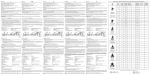
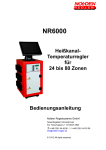
Fig. 1.0: MPACT-PLUS Front View
1)
2)
3)
4)
5)
6)
7)
8)
9)
Manual Charging handle.
Closing push button (ON).
Opening pushbutton (OFF).
Main contact position indicator.
Charging spring status indication.
Auxiliary Contacts.
PAMM.
Electronic trip unit.
Electronic release access lock.
Abb. 1.0: MPACT-PLUS Vorderansicht
1)
2)
3)
4)
5)
6)
7)
8)
9)
1-02
.
.
.
.
Handspannhebel
EIN Drucktaster
AUS Drucktaste
Schaltstellungsanzeige
Federkraftspeicherstellungsanzeige
Anschlussklemmen Hilfsschalter
Speichermodul PAMM
Elektronischer Auslöser
Anschlussklemmen Auslöser
.
.
.
.
.
.
.
.
. .
. .
. .
.
MPACT-PLUS
GENERAL INFORMATION
ALLGEMEINE INFORMATIONEN
The MPRO 27&50 Trip Units are electronic devices that interface with a
circuit breaker. They monitor the breaker phase currents, neutral current
and/or voltage and trips the breaker in the event of an over-current or
voltage related condition.
They also provide a standard ammeter, diagnostic features whilst the 50
variant includes communications. The Trip Unit can be removed or replaced
in the field by de-energizing and removing the cover of the circuit breaker.
The Trip Unit also connects with the circuit breaker flux shifter to provide
the electromechanical tripping function. A user interface is provided on the
front panel to allow adjustment of the Trip Unit's parameters.
Die MPRO 27&50 Auslöseeinheiten sind elektronische Geräte, die mit einem
Leistungsschalter zusammenarbeiten. Sie machen die
Schalterphasenströme, Neutralleiterströme und / oder Spannungen
sichtbar und lösen den Schalter im Falle eines Überstromereignisses oder
Spannungsvorgangs aus.
Sie verfügen über ein Standard Amperemeter, Diagnoseeinrichtungen für
50 Varianten inklusive der Kommunikation. Die Auslöseeinheiten können
entfernt und Vorort bei ausgeschaltetem Leistungsschalter ausgetauscht
werden, indem die Leistungsschalterfrontabdeckung entfernt wird. Die
Auslöseeinheit steht über eine mechanische Verbindung in Wirkkontakt und
ermöglicht somit eine elektromechanische Auslösungsfunktion. Über ein
Eingabefeld an der Frontseite der Auslöseeinheit hat der Anwender Zugriff
auf die verschiedenen Parameter der Auslöseeinheit.
ABBREVIATIONS AND ACRONYMS
Kurzworte und Abkürzungen
The abbreviations and acronyms in Tab. 1.0 used throughout this manual.
Die Kurzworte und Abkürzungen aus der Tab. 1.0 werden in diesem
Handbuch verwendet.
1.0 PRODUCT DESCRIPTION
1.0 Produktbeschreibung
Appearance
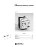
The Trip Unit includes a graphical LCD. The front panel being similar to that
depicted in Figure 1.1. Normally the device is set to the English language,
optionally French, German, Spanish or Chinese can be selected.
Aussehen
Die Auslöseeinheit besitzt ein grafisches LCD-Display. Die Frontplatte sieht
ähnlich der nachfolgenden Abb. 1.1 aus. Normalerweise ist das Gerät auf
die englische Sprache eingestellt, wahlweise kann Französisch, Deutsch,
Spanisch oder Chinesisch gewählt werden.
1.1 LCD ACCESS
1.1 LCD-Beschreibung
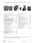
The trip unit has five function keys as shown in Figure 1.2.
All SETUP, STATUS, METER and EVENTS information is accessed through
these five keys.
Die Auslöseeinheit verfügt über fünf Funktionstasten, wie in Abb. 1.2
dargestellt. Auf alle SETUP-, ZÄHLER-, ZUSTAND und VORFALLInformationen wird über diese fünf Tasten zugegriffen.
------
------
UP: Scroll up or increment value
DOWN: Scroll down or decrement value
RIGHT: Next function or next page
LEFT: Previous function or previous page
ENTER: Save or set in to memory
1.0
GENERAL
TRIP UNIT
UP: Blättern nach oben oder Werterhöhung
DOWN: Nach unten oder Wertverringerung
RIGHT: Nächste Funktion oder nächste Seite
LEFT: Vorherige Funktion oder zurück zur vorherigen Seite
ENTER: Speichern oder in den Speicher setzen
Table 1.0
Denomination / Description
Tabelle 1.0
Kürzel / Beschreibung
GF
HSIOC
I
I²t
Groundfault
Hi set Instantaneous protection
Instantaneous Short circuit Current setting
'Slope' setting on ST or GF device
GF
HSIOC
I
I²t
Erdschluss
HSIOC Kurzschlussschutz
Kurzschlussstromschnellauslösungs Einstellung
"Anstieg" für ST- oder GF Schutz
Ie
Ig
Primary Current setting
Ground, or Earth fault Current setting
Ie
Ig
Stromeinstellung
Erd, oder Erdschlussfehler Einstellung
Ii
In
Instantaneous Short circuit Current setting
Current rating of Breaker
Ii
In
Kurzschlussschnellauslösungs Einstellung
Bemessungsstrom Leistungsschalter
Ir
Ist
LT or overload Current setting
ST or Timed Short circuit Current setting
Ir
Ist
Langzeit oder Überlastschutzeinstellung
ST oder zeitliche Kurzschlussstromeinstellung
LT
Long Time or Overload protection
LT
Langzeit oder Überlastschutz
LTDB
LT or overload time delay band
LTDB
LT oder Überlast-Verzögerungsbereich
MCR
RELT
Making Current Release
Reduced Instantaneous
MCR
RELT
Einschaltstromauslöser
RELT Reduzierte Schnellauslösung
ST
STDB
Short Time or Timed Short circuit Current setting
ST or short circuit time delay band
ST
STDB
Kurzzeit oder zeitliche Kurzschlussstromeinstellung
ST oder Kurzschluss-Verzögerungsbereich
x CT
Multiple of installed sensor rating
x CT
Vielfaches vom install. Wandlerstrom
x Ie
Multiple of Primary Breaker setting Ie
x Ie
Vielfaches vom Schalterwert Ie
x In
Multiple of Breaker Current rating
x In
Vielfaches vom Leistungsschalter Bemessungsstrom
x LT
Multiple of LT or overload Current setting
x LT
Vielfaches von LT oder Überlaststromeinstellung
1-03
MPACT-PLUS
Trip unit MPRO 27 & MPRO 50
APPENDIX
SCREEN MODE
OPERATION
PROTECTION
GENERAL
INTRO
Table 1.1: Overview table MPRO
1-04
Versions
MPRO 27-PLUS
MPRO 50-PLUS
MPRO 30-40
Breakers Supported & Protection features
MPACT frame 1+2
MPACT frame 1+2
MPACT frame 1+2
Long Time (overcurrent) 0.4-1, increments 0.05 22 bands.
Multiple classes to IEC 947-4.
x
--
Long Time (overcurrent) 0.4-1 with
increments of 0.01 multiple bands
IEC 947 class 20 only & IEC 255.
Long Time (overcurrent) 0.4-1, increments 0.05 44 bands.
Multiple classes IEC 947-4 and Fuse bands
--
x
Long Time (overcurrent) 0.4-1 with
increments of 0.01 multiple bands
IEC 947 & IEC 255.
Short Time
Instantaneous
Reduced Inst Setpoint
Ground Fault Trip
Ground Fault Alarm
Earth Fault - UEF / REF / SEF
Thermal Memory
MCR
High Set Inst (HSIOC)
x
x
-x
--12 min.
x
x
x
x
x
x
x
x
12 min.
x
x
x
x
-x
x
x
X
x
x
I/O (Physical I/O)
.
.
IN/OUTPUTS
Assignable outputs (4 avail) Assignable
Health indication relay
---
x
x
x (dedicated to specific functions)
x
INPUTs
General Inputs (4 avail)
Spring Charged Indication
Breaker Closed and Connected
Contact Position Switch
---x
x
--x
x
x
x
x
Status and Diagnostics:
Trip Target
Trip Info (Magnitude / Phase)
Trip Counter
Event Logger (trips, alarms, I/O)
Current Alarm Relay based on current level (load shedding)
Bad Health indication alarms
Good Health indication relay
Operation counter
Main contact maintenance indication
x
x
x
x
------
x
x
x
x
x
x
x
---
x
x
x
x
x
x
x
x
x
Hardware Test Interfaces
24V DC
110-130V DC or 110-240V AC
x
x
x
x
x
x
Miscellaneous
Settings lock / unlock
x
x
x
Metering
Current (PH-L1, PH-L2, PH-L3, N)
x
x
x
Communications
Modbus 4 wire
--
x
--
.
.
.
.
.
TRIP UNIT
MPACT-PLUS
1.1
Tabelle 1.1: Übersichtstabelle MPRO
MPRO 27-PLUS
MPRO 50-PLUS
MPRO 30-40
Schalter Schutzfunktionen
MPACT Bg 1+2
MPACT Bg 1+2
MPACT Bg 1+2
Langzeit (Überstrom) 0.4-1, Schrittweite 0.05/ 22 Bereiche
Mehrfachklassen zu IEC 947-4.
x
--
Langzeit (Überstrom) 0.4-1 in
Schritten von 0.01 Multibereich
IEC 947 class 20 nur & IEC 255.
Langzeit (Überstrom) 0.4-1, Schrittweite 0.05 / 44 Bereiche
Mehrfachklassen IEC 947-4 und Sicherungsbereich
--
x
Langzeit (Überstrom) 0.4-1 in
Schritten von 0.01 Multibereich
IEC 947 & IEC 255.
Kurzzeit
Schnellauslösung
reduz. Schnellauslösung Einstellung
Erdschlussfehlerauslösung
Erdschlussfehler Meldung
Erdschlussfehler - UEF / REF / SEF
Thermisches Gedächtnis
Einschaltstromauslöser MCR
HISOC Kurzschlussschutz (..gegen hohe Kurzschlussströme)
x
x
-x
--12 min.
x
x
x
x
x
x
x
x
12 min.
x
x
x
x
-x
x
x
X
x
x
I/O (Äußere I/O)
.
GENERAL
Versionen
.
EIN/AUSGÄNGE
Bestimmbare Ausgänge (4 vorhanden)
Zustandsanzeige Relais
---
x
x
x (für spezielle Funktionen geeignet)
x
EINGÄNGE
Generelle Eingänge (4 vorhanden)
Federspannanzeige
Schalter Geschlossen und angeschlossen
Kontaktpositionsschalter
---x
x
--x
x
x
x
x
Status und Diagnose:
Auslösungsziel
Auslösungsinfo Größe/ Phase)
Auslösungszähler
Vorfallregistrierung (Auslösung, Meldung, I/O)
Strommelderelais basierend auf Stromhöhe (Lastüberwachung)
Schlecht-Zustandsanzeige Meldungen
Gut-Zustandsanzeige Relais
Betriebszähler
Hauptkontakt Wartungsanzeige
x
x
x
x
------
x
x
x
x
x
x
x
---
x
x
x
x
x
x
x
x
x
Hardware Test Schnittstelle
24V DC
110-130V DC or 110-240V AC
x
x
x
x
x
x
Verschiedenes
Einstellung Sperren / Entsperren
x
x
x
Messung
Strom (PH-L1, PH-L2, PH-L3, N)
x
x
x
Kommunikation
Modbus 4 Drahtsystem
--
x
--
.
.
.
.
.
----------------------------------------------------------------------------------------------------------------------------------------------------------------------------.
1-05
APPENDIX
SCREEN MODE
OPERATION
PROTECTION
GENERAL
INTRO
MPACT-PLUS
1-06
Trip unit MPRO 27 & MPRO 50
1.2 Electrical Requirements
1.2 Elektrische Anforderungen
None: Plug in installation. Done on de-energized units.
Keine: Plug-in Installation. Durchführbar mit ausgeschalteten Geräten.
Equipment Interfaces
Schnittstellen
MPACT-PLUS Leistungsschalter Baugröße 1 und 2.
Auslöseeinheiten benötigen zum größten Teil keine direkte Leiterverbindung
zum Schalter. Alle Leitungen sind Verbindungen mit dem Leistungsschalter
oder Einschubträger.
Mpact Plus frame 1 & Frame 2 Circuit Breakers.
Trip units, for the most part, do not require direct connections to the
equipment. All wiring is intended to connect to the circuit breaker or
cassette.
Connections that are required for other equipment are the optional input,
and relay output, the neutral sensor and the 'Earth leg' CT which uses
specifically dedicated connection points on the breaker secondary
connection terminals.
On the MPRO 50 a signal Input (nr.1) can be programmed to allow for the
use of reduced instantaneous (RELT) set to OFF or used to trip the breaker.
Three other inputs (nr.2-4) can be individually set to 'OFF' or programmed to
trip the breaker .
Verbindungen sind erforderlich für andere Ausrüstungen, wie die optionale
Zonenselektivität (ZSI), Relais Ein- und Ausgabe und dem Neutralwandler,
die zu speziellen Anschlüssen an den Hilfstrennblöcken geführt werden.
Am MPRO 50 kann ein Signal-Eingang (Nr.1) so programmiert werden, dass
die Nutzung der reduzierten Schnellauslösung (RELT) oder den Schalter
auszulösen erlaubt wird. Drei andere Eingänge (Nr.2-4) können auf ‘AUS’
gesetzt werden oder so programmiert werden, dass der Schalter auslöst.
The MPRO 50 trip Unit has four output relays that can be assigned to the
following functions:
–- GF Alarm: Turns on, when GF alarm is activated (Group 1).
--· Over-current trip (GF, INST, LT, ST):
..Over-voltage trip turns ON the relay (Group 2)..
--· Current Alarm / Load shedding 1:
..Exceeding current alarm pick-up closes the relay contact (Group 4).
--· Current Alarm / Load shedding 2:
..Exceeding current alarm pick-up closes the relay contact (Group 5).
--· Health status:
..Relay contact will be closed or opened depending on the health contact
setting (Group 6)..
--· Reduced Instantaneous (RELT) Active (Group 7).
The trip unit must have the specific option enabled and present in order for
protective function to actuate the relay. The Trip Units can be optionally
supplied by a +24 VDC control power supply.
(Note: external +24 VDC control power is required for communication.)
All trip unit types have a connection to an auxiliary switch within the
breaker that senses the breaker's position.
1.3 COMMUNICATIONS
Die MPRO 50 Auslöseeinheit hat vier Ausgangsrelais, denen die folgenden
Funktionen zugeordnet werden können:
-- GF Meldung: ..schaltet, wenn die GF Meldung aktiviert wurde (Gruppe 1).
-- Überstromauslösung (GF, INST, LT, ST): ..schaltet Relais EIN (Gruppe 2).
-- Stromalarm / Lastüberwachung 1:
..Überschreitung schließt das Relais (Gruppe 4).
-- Stromalarm / Lastüberwachung 2:
..Überschreitung schließt das Relais (Gruppe 5).
-- Auslöserstatusangaben:
..Relaiskontakt öffnet oder schließt, je nach der gewählten
Kontakteinstellung (Gruppe 6).
-- RELT Schnellauslösung Aktiv (Gruppe 7).
Die Auslöseeinheiten müssen die spezifischen Optionen auch aktiviert
haben (als Beispiel: Schutzrelais müssen vorhanden und aktiviert sein, um
für die Schutzfunktion die Betätigung des Relais zu ermöglichen).
Alle Auslöseeinheiten können wahlweise mit einer +24 VDC
Stromversorgung betrieben werden.
(Hinweis: externe +24 VDC Steuerspannung ist für die Kommunikation
erforderlich.) Alle Auslöseeinheitentypen haben eine Verbindung zu einem
Hilfsschalter innerhalb des Leistungsschalters, der die Schalterstellungen
meldet.
1.3 KOMMUNIKATION
External +24 VDC control power is required for communications. MPRO 50
Trip Units support Modbus communication. Modbus connections are made
directly to wiring terminations located at the circuit breaker top. Internally
all Modbus connections are ran through the trip unit's top connectors,
which mate with a receptacle on the breaker frame.
Modbus
The MPRO 50 Trip Unit is fully compliant with Modbus Protocol. Full details
of the Modbus protocol can be found in the Modbus Protocol Specification.
Four wire Modbus 485 is supported. The link Host may operate at a 300,
600, 1200, 2400, 4800, 9600 or 19200-baud rate.
Eine externe +24 VDC Steuerspannung ist für die Kommunikation
erforderlich. Die MPRO 50 Auslöseeinheit unterstützt das ModbusKommunikationsprotokoll. Intern laufen alle Modbus-Verbindungen durch
die oberen Anschlüsse der Auslöseeinheit, die mit den Steckerbuchsen der
Schaltergrößen zusammenpassen.
Modbus
Die MPRO 50 Auslöseeinheit ist voll kompatibel mit dem Modbus-Protokoll.
Alle Details über das Modbus-Protokoll finden Sie in der Modbus-ProtokollSpezifikation. Vier-Draht Modbus 485 wird unterstützt.
Der Hostlink arbeitet mit einer 300, 600, 1200, 2400, 4800, 9600 oder 19200
Baudrate.
Fig. 1.1
LCD screen
Abb. 1.1
LCD Bildschirm
KEY pad
AUTO/MAN reset choice
Einstelltasten
AUTO/HAND Auswahl
Fig 1.2 Key pad
Abb. 1.2 Tasten
Up
Oben
Down
Unten
Right (Next)
Rechts (Nächster)
Left (Previous)
Links (Voriger)
Enter (Save)
Sichern
TRIP UNIT
MPACT-PLUS
2.0 OVER CURRENT PROTECTION FUNCTIONS
2.0 Überstrom-Schutzfunktionen
The Trip Units can provide the following over current protections:
--- Long Time
(Protection against Overload currents) LT
--- Short Time
(Time delayed Protection against Short circuit currents) ST
--- Instantaneous
(Optional Protection against Short circuit currents) I
--- Ground Fault Internal Summation
(Optional Protection against Ground Fault currents) GFsum
--- Ground Fault CT External Summation
(Optional Protection against Ground Fault currents) GFCt
--- Hi level Instantaneous Override
(Protection against High Short circuit currents) HSIOC
--- Making Current Release
(Protection against closure on a fault) MCR
--- Reduce Let Through Energy Instantaneous
(Optional Protection against Short circuit currents) RELT
Die MPRO-Auslöseeinheiten unterstützen die folgenden ÜberstromschutzFunktionen:
--- Langzeitschutz
(Schutz gegen Überlastströme) LT
--- Kurzzeitschutz
(Zeitverzögerter Schutz gegen Kurzschlussströme) ST
--- Schnellauslösung
(Optionaler Schutz gegen Kurzschlussströme) I
--- Erdschluss interne Summierung
(Optionaler Schutz gegen Erdschluss-Ströme) GFsum
--- Erdschluss CT externe Summierung
(Optionaler Schutz gegen Erdschlussströme) GFCT
--- HSIOC-Schutz
(Schutz gegen hohe Kurzschlussströme)
--- Einschaltstromauslöser
(Schutz gegen die Schließung auf einen Fehler) MCR
--- RELT-Schnellauslösung
(Optionaler Schutz gegen Kurzschlussströme RELT)
A full overview of the installed overcurrent protection devices and other
optional features per Trip Unit version is indicated in Tab. 2.0.
Eine vollständige Übersicht des installierten Überstromschutzes und andere
optionale Funktionen pro Auslöseeinheitenversion siehe Tab. 2.0.
2.1 Manual or Automatic reset function
2.1 Manuelle oder Automatische Reset-Funktion
The breaker reset mode can be chosen by a selector switch on the Trip Unit
front as indicated in figure 1.1. There are 2 possible positions or
configurations. (Figure 1.1: Manual/Automatic selector switch)
1) manual
In this configuration the assembly in the trip unit interlocks with a
mechanical lockout functionality of the circuit breaker. When the circuit
breaker trips a mechanical interlock changes state.
This Interlock drives a assembly in the trip unit forward so that the depicted
button “pops” out from the front of the trip unit. This device also operates
an optional Bell Alarm contact mounted in the circuit breaker.
In order to re-close the breaker; the mechanical interlock must be reset by
depressing the button on the front of the trip unit. This also resets the Bell
Alarm contact in the circuit breaker, if present.
2) auto
In this configuration the assembly in the trip unit is mechanically restrained
so that the depicted button does not “pop out” from the front of the trip
unit. The optional Bell Alarm contact in the circuit breaker also does not
change state.
The breaker can be re-closed (Either manually or using a closing coil)
without resetting the button since it is held in the reset position.
Der Leistungsschalter-Reset-Modus kann mit einem Wahlschalter auf der
Frontseite der Auslöseeinheit, wie in Abb.1.1 gezeigt, bestimmt werden. Es
gibt 2 mögliche Stellungen oder Konfigurationen.
1) Manuell (Hand)
In dieser Konfiguration verriegeln die Auslöseeinheiten mit einer
mechanischen Sperrfunktion des Leistungsschalters. Wenn der
Leistungsschalter auslöst ändert eine mechanische Verriegelung ihren
Zustand.
Diese Verriegelung treibt eine Mechanik in der Auslöseeinheit an, so dass
der abgebildete Knopf aus der Vorderseite des Auslöseeinheit
hervorspringt. Dieses Gerät betätigt außerdem einen im Leistungsschalter
montierten, optionalen Störmeldeschalter.
Zur Wiederherstellung des Schaltzustands, muss die mechanische
Verriegelung durch Drücken der Taste an der Vorderseite der Auslöseeinheit
zurückgesetzt werden. Dies setzt auch den Störmeldeschalter im
Leistungsschalter, falls vorhanden, zurück.
2) Automatik
In dieser Konfiguration verhält sich die Auslöseeinheit mechanisch so, dass
die abgebildete Taste nicht hervorspringt. Der optionale Störmeldeschalter
im Leistungsschalter verändert nicht seinen Zustand. Der Leistungsschalter
kann wieder geschlossen werden (entweder manuell oder mit einem
Abrufmagneten), ohne das Zurücksetzen der Taste, da er in der
Resetstellung gehalten wird.
2.2 Power requirements
2.2 Stromversorgung
A small amount of power is necessary to energize the liquid crystal display
(LCD) during setup, for viewing breaker status and for metering displays.
Nur eine kleine Leistung ist erforderlich, um die Energie für das Liquid
Crystal Display (LCD) während der Einstellungen aufzubringen, sowie für die
Anzeige von Schalterstatus und Messung.
Die Stromversorgung kann eine der folgenden Optionen sein:
-- Stromfluss: Leistungsschalter-Wandler liefern die notwendige
Versorgung für die LCD-Energie, wenn mindestens 20% des Wandlerstroms
fließt.
-- +24 VDC Steuerspannung
The power sources can be one of the following:
-- Current flow: Breaker current sensors provide sufficient power to
energize the LCD when at least 20% of the sensor's ampere rating is
flowing.
-- +24 VDC control power
--Test kit Catalogue No. GTUTK20
The device has a built in 24 VDC control power supply that can be powered
up through a standard mains connection.
- The MPRO 50 Trip Unit requires external +24 VDC control power for
communication.
PROTECTION
2.0
-- Der Tester, Katalog-Nr GTUTK20
Das Gerät verfügt über eine eingebaute 24VDC-Stromversorgung, die über
einen Standard-Netzanschluss aufgeladen werden kann.
Die MPRO-Auslöseeinheiten erfordern eine externe +24 VDC Versorgung
für die Kommunikation.
2-01
MPACT-PLUS
Trip unit MPRO 27 & MPRO 50
ENGLISH
PROTECTION
GENERAL
INTRO
Table 2.0 MPRO Electronic Trip Unit Functionality
Setting Interface
Long Time
or
Overload Current Protection
MPRO 27+
MPRO 50+
Remarks
LCD Screen allowing access to 4 distinct Menu's
X
X
--
Touch pad adjustments
X
X
--
Multilingual
X
X
--
Adjustable Manual or Automatic RESET option
X
X
--
13 Current settings Ir
1, 0.95, 0.9. 0,85, 0.8, 0.75, 0.7, 0.65, 0.6, 0.55, 0.5, 0.45 & 0.4 x ...
x Breaker rating In
X
22 Thermal Protection (C type) time bands available Ranging from
class 0.5 to 40 (bands at 7.2 x Ir)
X
X
--
22 I t Protection (F type {fuse} ) time bands available
-
X
--
Neutral Protection 0-50%-63%-100%
X
X
--
Possibility to Switch OFF
-
X
--
Cooling function and Thermal memory
X
X
X
-
X
X
X
--
X
--
17 Time delay settings (STDB) ranging from 30 to 940 milliseconds
delay setting result in a 90 to 1000 Milliseconds Clearing time
X
X
--
Clearance times to IEC 40979-1 and IEC 60364
X
X
--
X
X
--
Ii Setting RANGE from 2 to 15 x Breaker Rating In
X
X
Steps of 0.5 (A total of 28 settings)
X
X
--
Possibility to Switch OFF
X
X
--
Selective Execution
X
X
--
Fixed Instantaneous or HSIOC protection
X
X
--
Ii Setting RANGE from 1.5 to 15 x Ie (Primary Setting)
-
X
--
Steps of 0.5 (A total of 29 settings)
-
X
--
Possibility to Switch OFF
-
X
---
2
Setting RANGE from 1.5 to 12 x Ir (LT setting)
Steps of 0.5 (A total of 22 settings)
Short Time
Possibility to Switch OFF
Short Circuit Current Protection
2
APPENDIX
SCREEN MODE
OPERATION
3 I t Protection time bands available
Instantaneous
Short Circuit
Current Protection
Standard
Reduced
Remote and Local ON and OFF with position indication signal.
N
Steps of 0.01 (A total of 92 settings)
O
O
--
Possibility to Switch OFF
O
O
--
13 Time delay settings (GFDB) ranging from 50 to 840 milliseconds
O
O
--
delay setting resulting in a 110 to 900 Milliseconds Clearing time
O
O
--
Clearance times to IEC 40979-1 and IEC 60364
O
O
--
O
O
--
O
O
X
X
O
O
O
O
O
X
X
--
X
X
X
X
--
X
-
X
X
--
X
X
X
X
--
General Relay Outputs (4 available)
X
Communication 2 way
-
X
N
Modbus
24V DC Auxiliary Power supply
X
X
X
--
Text kit with Power support function
X
X
--
4
Residual Principle (UEF application possible)
Source Ground Return Principle
UEF, REF and SEF applications possible
Combinations of UEF, REF and SEF applications possible
Current Measurement (L1, L2, L3, N)
Trip Target (trip reason indication)
Trip Info (Magnitude / Phase)
Trip Counter
Event Logger (trip events)
Relay based on current level (load shedding)
Good & Bad Health Indicator
Watchdog
General Inputs (4 available)
Key
X - Present ; O = Optional , - = Not Possible
Remarks If an N is indicated a 24V auxiliary power supply is required.
(1) Without a 24V auxiliary power supply, the lowest setting is 0.2.
2-02
--
X
1 Fuse I t Protection time band available
Other
--
O
2
Data Acquisition
&
Diagnostics
--
-
(1)
2 I t Protection time bands available
Measurement package
--
O
Setting RANGE from 0.1 to 1 x In (Breaker Rating)
Ground
or
Earth
Fault Protection
X
-------
-----
N
MPACT-PLUS
Deutsch
Tabelle 2.0 MPRO Elektronik-Auslöseeinheit: Funktionen
Einstellschnittstelle
Langzeit
&
Überlaststromschutz
MPRO 50+
Hinweise
LCD Bildschirm erlaubt Zugang zu 4 eindeutigen Menü
X
X
--
Eingabe über Bedienfeld
X
X
--
Mehrsprachig
X
X
--
Justierbare Manuelle oder Automatik-Rücksetzmöglichkeit
X
X
--
13 Stromeinstellungen Ir
1, 0.95, 0.9. 0,85, 0.8, 0.75, 0.7, 0.65, 0.6, 0.55, 0.5, 0.45 & 0.4 x ...
x Schalternennstrom In
X
X
--
22 I²t Therm. Schutzbereiche (C Typ) verfügbare Bandbreite von
Klasse 0.5 bis 40 (Bereich bis 7.2 Ir)
X
X
--
22 I²t Schutzbereiche (F-Typ Sicherung) sind verfügbar
-
X
--
Neutralleiterschutz 0-50%-63%-100%
X
X
--
AUS-Schaltmöglichkeit
-
X
--
Abkühlungsfunktion und Thermisches Gedächtnis (Speicherung)
X
X
--
Ii Einstellbreite von 2 - 15 xIe Einstellung
X
X
--
AUS-Schaltmöglichkeit
X
X
-
X
--
17 Zeitverzögerungseinstellungen (STDB) von 30-940 ms
Verzögerungszeit ergibt 90-1000ms Ausschaltzeit
X
X
--
Ausschaltzeit nach IEC 409791 und IEC 60364
X
X
--
3 I²t Schutzbereiche sind verfügbar
X
X
--
Ii Setting RANGE from 2 to 15 x Breaker Rating In
X
X
--
Schritte von 0.5 (gesamt 28 Einstellungen)
X
X
--
AUS-Schaltmöglichkeit
X
X
--
Selektive Ausführung
X
X
--
Unverstellbarer Schnellauslöser oder HSIOC Schutz
X
X
--
Ii Einstellbreite von 1,5 - 15 xIe-Einstellung
-
X
--
Schritte von 0.5 (gesamt 29 Einstellungen)
-
X
--
AUS-Schaltmöglichkeit
-
X
---
Schritte von 0.5 (gesamt 22 Einstellungen)
Kurzzeit
&
Kurzschlussstromschutz
KurzschlussschnellAuslösungsschutz
MPRO 27+
Standard
Reduziert
Fern- und Vorort EIN und AUS mit Stellungsanzeigemeldung
-
X
O
O
N
Schrittweise 0.01 (gesamt 92 Einstellungen)
O
O
--
AUS-Schaltmöglichkeit
O
O
--
13 Zeitverzögerungseinstellungen (GFDB) von 50-840 ms
O
O
--
Verzögerungseinstellung sich ergebend in 110-900ms Ausschaltzeit
O
O
--
Ausschaltzeit nach IEC 409791 und IEC 60364
O
O
--
2 I²t Schutzbereiche sind verfügbar
O
O
--
1 Sicherung I 4 t Schutz-Zeitbereich ist verfügbar
O
O
X
X
O
O
O
O
O
X
X
--
X
X
X
X
--
X
-
X
X
--
X
X
X
X
--
Generelle Ausgänge (4 verfügbar)
X
Kommunikation 2 Draht
-
X
N
Modbus
24V DC Fremdversorgung
X
X
X
--
Tester mit Einspeisefunktion
X
X
--
Einstellbereich von 0,1 bis 1 xIn (Schalterwert)
Masse- oder Erdschlussschutz
(1)
Fehlerstromprinzip (UEF Anwendung möglich)
"Source Ground Return"-Methode
UEF, REF und SEF Anwendung möglich
Kombination von UEF, REF und SEF Anwendungen möglich
Messdatenerfassung
Strommessung (L1, L2, L3, N)
Auslösezielvorgabe (Auslösegrundanzeige)
Auslöseinformation (Größenordnung / Phase)
Datenübernahme
&
Diagnose
Auslösungszähler
Vorfallsregistrierung (Auslösevorfälle)
Relais basiert auf Stromwert (Lastüberwachung)
Gut & Schlechtzustands-Anzeige
Überwachung (Watchdog)
Generelle Eingänge (4 verfügbar)
Sonstiges
--
2.0
PROTECTION
TRIP UNIT
-------
-----
N
Zeichen : X = Vorhanden; O = Optional; - = Nicht möglich
Hinweis: Wenn ein N angezeigt ist, so wird eine 24V Fremdversorgung benötigt.
(1) Ohne 24V Fremdspannungsversorgung, ist 0.2 der niedrigste Einstellwert.
2-03
INTRO
GENERAL
PROTECTION
OPERATION
SCREEN MODE
APPENDIX
MPACT-PLUS
Trip unit MPRO 27 & MPRO 50
3.0 OPERATION
3.0 BETRIEB
3.1 OPERATING MODES
3.1 BETRIEBSARTEN
MPRO 27 and 50 plus Trip Units have four operating modes: SETUP, METER,
STATUS and EVENTS. These are accessed through the five keys on the Trip
Unit front. (see Figure 1.2: Key pad functions)
EntelliGuard G Auslöseeinheiten können vier Betriebsarten: Einrichten
(SETUP), Messen (ZÄHLER), ZUSTAND und Vorgänge (VORFALL) anzeigen.
Diese Anzeigen werden über die fünf Tasten auf der Auslöseeinheitenfront
vorgenommen. (see Abb. 1.2: Tastenfunktionen)
3.2 SETUP MODE
3.2 SETUP (Einrichtungs-) Modus
SETUP Mode programming procedure applies to all trip unit types.
The SETUP procedures should only be repeated if the trip unit or the
protection characteristics are changed, requiring different set points and
time-delays.
All trip units provide long time over current protection, long time delay, and
some form of short circuit current protection when installed in circuit
breakers. All other functions are optional.
If a specific set of trip unit functions, such as Ground Fault current
protection is not installed (see table 3.0) that function will not appear on the
trip unit display. Ignore setup mode instructions for such functions. The trip
unit must be powered by one of the indicated four methods during SETUP.
(see Chapter 4.1)
Die SETUP-Modus Programmierung gilt für alle Auslöseeinheiten.
Das Setup-Verfahren sollte nur wiederholt werden, wenn die Auslöse- oder
Schutzmerkmale geändert werden müssen oder andere Zeitverzögerungen
etc. verlangt werden.
Alle Auslöseeinheiten liefern Langzeit-Überstromschutz,
Langzeitverzögerung und einige Formen von Kurzschlussstromschutz,
wenn sie im Leistungsschalter installiert sind. Alle anderen Funktionen sind
optional.
Wenn eine bestimmte Reihe von Auslösefunktionen, wie z. B. Schutzrelais
oder Kurzschlussstromschutz nicht installiert sind (siehe Tab. 3.0), so wird
die Funktion auch nicht auf der Auslöseeinheit angezeigt. Ignorieren Sie
deshalb die Setup-Anweisungen für solche Funktionen. Das Auslösegerät
muss nach einer der beschriebenen Arten während des Setup bedient
werden: (siehe auch Kapitel 4.1)
-- Press UP or DOWN until the SETUP mode is selected.
-- Press RIGHT or LEFT to access the functions in the SETUP mode.
-- Press ENTER to save desired values.
-- Press RIGHT to advance to the next function.
-- Drücken Sie UP (Rauf) oder DOWN (Runter), bis zum SETUP-Modus.
-- Drücken Sie RIGHT (Rechts) oder LEFT (Links), für SETUP-Funktionszugriff.
-- Drücken Sie die ENTER (Eingabetaste), zur gewünschten Wertesicherung
-- Drücken Sie RIGHT (Rechts), um zur nächsten Funktion zu gelangen.
3.2.1 Entering Set points into Memory
3.2.1 Eingabe der Sollwerte in den Speicher
1. Press UP or DOWN to select SETUP.
2. Press LEFT to select the desired protection to change.
3. Press UP or DOWN to change values. The values will start flashing.
4. Press ENTER to store the value into the memory. The displayed value
stops flashing and the save icon appears on the top of the LCD. This
indicates that the value has been stored in memory and is active.
5. Confirm settings on the trip unit after making changes by exiting and reentering SETUP mode and rechecking each changed setting.
1. Drücken Sie OBEN oder UNTEN, um SETUP zu selektieren.
2. Drücken Sie LINKS oder RECHTS, um die gewünschte Schutzart zu
ändern.
3. Drücken Sie RAUF oder RUNTER, um Werte zu ändern. Die Werte
beginnen zu blinken.
4. Drücken Sie ENTER, um den Wert in den Speicher zu setzen. Der
angezeigte Wert blinkt dann nicht mehr und das Sicherungssymbol
erscheint auf dem oberen Rand des LCD-Monitors. Dies deutet darauf hin,
dass der Wert gespeichert wurde und aktiv ist.
5. Testen Sie die Einstellung der Auslöseeinheit nach einer Änderung durch
verlassen und wieder in den SETUP-Modus springen, um jede neue
Einstellung zu überprüfen.
3.3 Protection modes
3.3.1 Long Time Pickup (Overload Protection setting) Ir
Installed in all Trip Units types the first SETUP mode display is always the
Long Time Pickup setpoint. This setpoint establishes the breaker's adjusted
or regulated ampere rating Ir.
The definite current setting Ir is set on the LT setting screen as a fraction of
the user current value Ie. (xLT = LT multiplier x In).
There are 13 Long Time or Ir settings ranging from 0.40 to 1.00 times x the
breaker rating (In) in steps of 0.05. The pickup value is set at a value of
approximately 1.12 x the setting with a tolerance of ±1 0%. An additional
accuracy degradation of ±5% occurs when waveforms with significant
harmonic distortion are present.
3.3.1.1 Long Time Delay (On overload Protection) LTD
The MPRO 27 plus trip unit type offers 22 long time delay bands that have a
shape similar to that of the thermal element of a thermal magnetic circuit
breaker.
The MPRO 50 plus trip unit type offers a total of 44 long time delay bands.
22 long time delay bands that have a shape similar to that of the thermal
element of a thermal magnetic circuit breaker. (= MPRO 27). A second,
additional set of 22 bands offering typical fuse equivalents are present.
Table 3.2 contains the minimum and maximum delay times on the 22 fuse
equivalent bands. All bands are depicted as Time Current Diagram in
appendix 5 of this Application manual.
3.3.2 Short Time Pickup (Delayed Short Circuit Protection) ST
Installed in all Trip Units types the second SETUP mode display is always the
Short Time Pickup setpoint. The Short Time Pickup function establishes the
current at which a timed short time trip is activated (Ist) and is adjusted in
function of the Long Time Pickup setting Ir. The choices of pickup settings
3-00
3.3 Schutzarten
3.3.1 Langzeiteinstellungen (Überlastschutz Einstellung) Ir
In allen Auslöserarten wurde als erste SETUP-Modusanzeige immer die
Langzeit-Sollwert-Einstellung installiert. Dieser Sollwert richtet den
Leistungsschalter Stromwert Ir ein.
Es gibt 13 Überlastschutz-Einstellungen im Bereich von 0,40 bis 1,00 x CT in
Schritten von 0,05. Der Spitzenwert ist annähernd der 1,12 fache
Einstellwert mit einem Toleranzbereich von -10% bis +10%. Eine zusätzliche
Herabsetzung der Genauigkeit um ± 5% tritt für Kurvenformen mit
erheblicher harmonischer Verzerrung ein.
3.3.1.1 Langzeitverzögerung (für Überlastschutz) LTD
Die MPRO 27-Auslöseeinheit bietet 22 Langzeit-Verzögerungsbereiche, die
der Verzögerungsart der thermischen Elemente eines thermischmagnetischen Leistungsschalter ähneln.
Die MPRO 50-Auslöseeinheit bietet insgesamt 44 LangzeitverzögerungsBereiche, 22 Langzeitverzögerungsbereiche die der Verzögerungsart der
thermischen Elemente eines thermisch-magnetischen Leistungsschalter
ähneln und zusätzlich 22 Bereiche mit Sicherungscharakteristik.
Die Tabelle 3.2 beinhaltet die minimale und maximale Verzögerungszeit der
22 ähnlichen Sicherungsbänder. Die Bereiche sind dargestellt als ZeitStrom-Diagramm im Anhang 5.
3.3.2 Kurzzeitverzögerung (verzögerter Kurzschlussschutz) ST
In allen Arten von Auslöseeinheiten zeigt der zweite SETUP-Modus immer
den Kurzzeitverzögerungs-Einstellwert. Durch die KurzzeitverzögerungsFunktion wird der Strom gesetzt, auf dem eine zeitliche Kurzzeit-Auslösung
aktiviert (Ist) ist, in Abhängigkeit zur Langzeitauslösungs-Einstellung Ir. Die
Wahl der Einstellungen liegt zwischen 1,5 und 12,0 (1) mal der Langzeit-
MPACT-PLUS
TRIP UNIT
3.3
are from 1.5 to 12.0 (1) times the long time setting, xLT ( Ir) , in steps of 0.5
xLT (Ir),
The ST pickup value (Ist) tolerance band is ± 10% of the set point. An
additional accuracy degradation of ±5% occurs when waveforms with
significant harmonic distortion are present.
Einstellung, xLT (Ir), in Schritten von 0,5 xLT (Ir).
Der ST Einstellwert (Ist)-Toleranzbereich beträgt -10% bis +10% des
Einstellwertes. Eine zusätzliche Genauigkeitsabweichung von ± 5% tritt für
Kurvenformen mit erheblicher harmonischer Verzerrung ein.
3.3.2.1 Short Time Delay
(Verzögerung auf verzögertem Kurzschlussschutz)
Beide MPRO-Auslöseeinheiten bieten eine Kurzzeit-Verzögerungsfunktion
mit beiden, einer Steigungs- und einer festen VerzögerungsbereichEinstellung. Die Steigungen und Verzögerungen sind unabhängig wählbar.
Die Steigungseinstellung besteht aus drei I²t (1, 2, 3) und einer festen
Verzögerung. Der feste Verzögerungsbereich hat 17 konstante Zeitbereiche.
Die minimalen und maximalen Verzögerungen werden in Tabelle 3.2
dargestellt. Die Bereiche beider, die Steigungs- und feste Verzögerungsart,
werden als Auslösekurven in der Anlage dieses Handbuchs dargestellt.
3.3.2.1 Kurzzeit-Verzögerung STDB
(Delay on delayed Short Circuit Protection) STDB
Both trip unit types have a Short Time Delay function with both a slope
setting and a fixed delay band setting. The slope and delay are
independently selectable. The slope setting consists of three I2T slopes (1, 2,
3) and a fixed delay. The fixed delay bands have 17 constant time bands
The minimum and maximum delay times are indicated in table 3.2. The
bands of both the slope and fixed delay types are depicted as Time Current
Diagram in appendix A of this Application manual.
3.3.3 Selektive Schnellauslösung (I)
Installed in all Trip Units types the third SETUP mode display is the
adjustable Selective Instantaneous over current protection.
This function causes an undelayed breaker trip when the chosen current
level (Ii) and proper waveform is reached.
The pickup value may be set in steps of 0.5 x the set user current value In
from 2.0 xIe to 15 x In.
The Instantaneous pickup accuracy is ± 10%. The trip units have a userselectable switchable instantaneous over current , an additional value of
OFF appears at the end of the listing of numerical values. Choose this
setting to disable instantaneous protection.
The bands are depicted as Time Current Diagram in appendix A of this
Application manual.
In allen MPRO-Auslöseeinheiten des dritten SETUP-Modusdisplays ist der
einstellbare selektive Kurzschlussschnell-Auslösungsschutz installiert.
Dieser Schutz verursacht eine verzögerungsfreie Schalterauslösung, wenn
das gewählte Stromniveau (Ii) und die ordnungsgemäße Kurvenform
erreicht ist. Der Einstellwert kann in Schritten von 0,5x auf die eingestellten
Nutzer-Stromwerte von 2,0 xIe bis 15 xIe gesetzt werden.
Die Schnellauslösungs-Einstellungsgenauigkeit liegt bei 10%. Die MPROAuslöseeinheiten haben einen vom Anwender wählbaren
Schnellauslösungs-Überstrom, ein zusätzlicher AUS-Wert erscheint am
Ende der Auflistung der Zahlen. Wählen Sie diese Einstellung zum
deaktivieren des Schutzes.
Die Bereiche sind als Auslösekurven im Anhang dieses Handbuchs
dargestellt.
OPERATION
3.3.3 Selective Instantaneous Protection (I)
Table 3.0 : Overload Tripping times at indicated overload levels per selected LTD band , in Seconds. (Cmin -2-21-Cmax.)
Table 3.0 : Auslösezeiten bei angezeigtem Überlastlevel des gewählten LTD Bereiches , in Sekunden. (Cmin -2-21-Cmax.)
x Ir
Cmin
C-2
C-3
C-4
C-5
C-6
C-7
C-8
C-9
C-10 C-11 C-12 C-13 C-14 C-15 C-16 C-17 C-18 C-19 C-20 C-21 Cmax
1.5
Maximum
7.8
23.4
46.7
62.3
93.4
125
156
187
218
249
280
311
374
436
498
560
623
685
747
810
872
934
Minimum
4.0
12.0
24.0
32.0
48.0
64.1
80.1
96.1
112
128
144
160
192
224
256
288
320
352
384
416
448
480
3
Maximum
1.3
3.86
7.73
10.3
15.5
20.6
25.8
30.9
36.1
41.2
46.4
51.5
61.8
72.1
82.4
92.7
103
113
124
134
144
155
Minimum
0.80
2.41
4.82
6.43
9.64
12.9
16.1
19.3
22.5
25.7
28.9
32.1
38.6
45.0
51.4
57.8
64.3
70.7
77.1
83.6
90.0
96.4
Maximum
0.21
0.62
1.24
1.66
2.49
3.32
4.15
4.98
5.81
6.64
7.47
8.30
9.96
11.6
13.3
14.9
16.6
18.3
19.9
21.6
23.2
24.9
Minimum
0.13
0.40
0.81
1.07
1.61
2.15
2.69
3.22
3.76
4.30
4.83
5.37
6.45
7.52
8.60
9.67
10.7
11.8
12.9
14.0
15.0
16.1
7.2
10b
Motor Protection Class to IEC 947-4
10
20
30
40
Table 3.1 : Overload Tripping times at indicated overload levels per selected LTD band , in Seconds. (Fmin -2-21-Fmax.)
Table 3.1 : Auslösezeiten bei angezeigtem Überlastlevel des gewählten LTD Bereiches , in Sekunden. (Fmin -2-21-Fmax.)
x Ir
Fmin
F-2
F-3
F-4
F-5
F-6
F-7
F-8
F-9
F-10
F-11
F-12
F-13
F-14
F-15
F-16
F-17
F-18
F-19
F-20
F-21 Fmax
1.5
Maximum
1.44
4.19
7.62
11.9
17.2
23.9
32.3
42.8
56
72
93
118
150
190
239
302
380
477
600
752
942
Minimum
0.64
1.87
3.39
5.30
7.67
10.7
14.4
19.0
25
32
41
53
67
85
107
135
169
213
267
335
419
514
3
Maximum
0.09
0.26
0.48
0.74
1.08
1.50
2.01
2.67
3.49
4.51
5.80
7.39
9.39
11.9
15.0
18.9
23.8
29.9
37.5
47.0
58.9
72.1
Minimum
0.04
0.12
0.21
0.33
0.48
0.67
0.90
1.19
1.55
2.01
2.57
3.29
4.18
5.29
6.68
8.41
10.6
13.3
16.7
20.9
26.2
32.1
7.2
Maximum
0.07
0.08
0.09
0.11
0.12
0.14
0.18
0.22
0.28
0.36
0.45
0.57
0.72
0.90
1.13
1.42
1.78
2.18
Minimum
0.01
0.02
0.03
0.04
0.05
0.06
0.08
0.10
0.13
0.16
0.20
0.25
0.32
0.40
0.50
0.63
0.79
1.03
1153
3.3.3.1 High Set Instantaneous Protection (HSIOC)
3.3.3.1 Kurzschlussschutz (HSIOC)
HSIOC is also known as Override Pickup. The trip units used in the Mpact
circuit breakers are provided with an override instantaneous trip.
– The HSIOC setting is normally set at 100% of the circuit breaker Icw
rating. (see table 3.3)
HSIOC ist auch bekannt als "Override Pickup". Die Auslöseeinheiten der
MPACT-PLUS-Leistungsschalter sind mit einer "Override Schnellauslösung"
versehen:
-- Die HSIOC Einstellung ist normalerweise auf 100% des Schalter IcwWertes gesetzt. (siehe Tabelle 3.3)
3.3.4 Making Current Release (MCR)
3.3.4 Einschaltstromauslöser (MCR)
Every Mpact circuit breaker uses a making current release that is
specifically designed to prevent damage to the circuit breaker when it is
inadvertently closed on a fault.
The making current release is related to the circuit breaker's close and latch
rating and is set at 50kA.
The MCR pickup is activated at the time the circuit breaker closes and for six
cycles thereafter. When the six cycles are over, the threshold changes to the
HSIOC pickup setting.
Jeder MPACT-Leistungsschalter verwendet einen Einschaltstromauslöser,
speziell zur Vermeidung von Schäden am Leistungsschalter, wenn dieser
auf einen Fehler schaltet.
Die Einschaltstromauslöser Werte sind auf die Leistungsschalter Schließund Verriegelungswerte abgestimmt und auf 50kA gesetzt.
Der MCR-Einstellwert ist zum Zeitpunkt der Leistungsschalter Schließung
und für sechs Zyklen danach aktiviert. Wenn die sechs Zyklen vorbei sind,
ändert der Schwellenwert zur HSIOC Einstellung.
3-01
INTRO
MPACT-PLUS
Trip unit MPRO 27 & MPRO 50
3.3.5 Reduced Energy Let-Through Instantaneous Protection
(RELT)
3.3.5 RELT-Schutz
The MPRO 50 trip unit has a Reduced Let-Through Energy Instantaneous
function (RELT) which can be enabled in the menu, via a 24 VDC/AC signal to
INPUT 1 or via serial communications. (MODBUS if installed)
The RELT function provides a faster instantaneous trip function that may be
used in cases where a faster and more sensitive protection against short
Die MPRO-Auslöseeinheit bietet eine "Reduced Energy Let-Through
Instantaneous Protection" RELT-Funktion, die möglicherweise über die
Auslösertastatur freigegeben wird, über ein 24 VDC/AC Signal am Eingang 1
oder über die serielle Kommunikation. (Modbus falls installiert)
Die RELT-Funktion bietet eine schnellere Schnellauslösungsfunktion, die
verwendet werden kann, wenn ein schnellerer und empfindlicherer Schutz
APPENDIX
SCREEN MODE
OPERATION
PROTECTION
GENERAL
Table 3.2 : Short Time tripping times at indicated levels per selected STDB band -I²t OFF. in ms (²)
Tabelle 3.2: Kurzzeit-Auslösung..Sicherungs ähnliche Bereiche.
x Ir
1.5 x
±10%
12 x
±10%
Min
2
3
4
5
6
7
8
9
10
11
12
13
14
15
16
Max
Tripping
90
100
110
120
170
190
240
270
300
340
400
450
600
700
800
900
1000
Non Tripping
30
40
50
60
110
130
180
210
240
280
340
390
540
640
740
840
940
Tripping
90
100
110
120
170
190
240
270
300
340
400
450
600
700
800
900
1000
Non Tripping
30
40
50
60
110
130
180
210
240
280
340
390
540
640
740
840
940
(1) On Envelope 3 type limited to 10 x Ir. (2)Timings in Red meet the requirements of the IEC 60479-1 and IEC 60364 standards at a frequency of 50 cycles.
1) Baugröße 3 limitiert auf 10 x Ir.- (2) Rote Eintragungen stimmen mit den Anforderungen von IEC 60479 mit einer Frequenz von 50 Hz überein.
circuits is required temporarily.
The device is set separately and has s pickup value that can be set in steps
of 0.5 x the set user current value Ie with a range of 1.5x In to 15x In.
To allow the use of the RELT function a input needs to be set to the RELT
function and to 'ON' in the trip unit set up menu . A relay output indicating
that the RELT is operational can be optionally set up in the same manner.
Um die Verwendung der RELT-Funktion zu nutzen, muss eine Eingang auf
die RELT Funktion gesetzt werden und "EIN" im Menü eingerichtet werden.
Ein Relaisausgang der darauf hinweist, dass die RELT-Funktion
betriebsbereit ist kann optional in gleicher Weise gesetzt werden.
3.3.6 Ground Fault Protection (GFsum)
3.3.6 Erdschlussschutz (GFsum)
Both MPRO 27 and 50 Trip Units can optionally be equipped with a ground
fault protection that operates on a residual principle.
The device utilizes the internal Rogowksi sensors in the circuit breaker to
measure and to residually sum all phase and neutral currents. When the
groundfault option is chosen on a 3 pole breaker an additional 4th external
sensor is required for most applications (4 wire). The distance between the
circuit breaker and the external sensor is limited to 10 meters (33 ft ).
The GF pickup value tolerance band is ±15% of the set current (Ig). The
ground fault pickup settings are set as multiples of the circuit breaker
current (In) in steps of 0.01.
Without an auxiliary supply the setting range is limited to 0.2 to 1 x In.
When a +24V DC control voltage supply is connected the setting range is
increased to 0.1 to 1 x In.
Die MPRO-Auslöseeinheiten können optional mit einem Erdschlussschutz
ausgerüstet werden, der mit einem Fehlerstrom-Prinzip arbeitet (GFsum),
Der Schutz nutzt die internen Rogowski-Wandler im Schalter zum Messen
und zum Summieren aller übrigbleibenden Phasen- und Neutralströme.
Wenn die Erdschluss-Option mit einem 3-poligen Leistungsschalter gewählt
wird, ist ein zusätzlicher 4ter externen Wandler für die meisten
Anwendungen (4-Draht) erforderlich. Der Abstand zwischen dem
Leistungsschalter und dem externen Wandler ist auf 10 Meter begrenzt.
Der GF Einstellwert-Toleranzbereich ist 15% des eingestellten Stroms (Ig).
Die Erdschluss-Einstellwerte sind als Vielfaches von xCT (CT = In des
Leistungsschalters) in Schritten von 0,01 xCT einstellbar.
Ohne Hilfsspannung ist der Einstellbereich auf 0,2 bis 1 xCT begrenzt. Wenn
eine +24VDC-Spannungsversorgung angeschlossen ist, erhöht sich der
Einstellbereich auf 0,1 bis 1 xCT.
3.3.6.1 Ground-Fault Delay (GFDB)
3.3.6.1 Verzögerter Erdschluss-Schutz (GFDB)
This function sets the time delay before the breaker trips when a groundfault pickup current has been detected.
The Ground Fault Delay has three variants, a type with a fixed time delay
bands, two I2T slopes or a steeper fuse type slope.
One of fourteen fixed time bands can be selected. The fixed delay bands are
listed in Table 3.4. The bands and slopes are depicted as Time Current
Diagram in appendix A of this Application manual.
Diese Funktion setzt die Zeitverzögerung bevor der Leistungsschalter
auslöst, wenn ein Erdschluss-Fehlerstrom erkannt wurde.
Der verzögerte Erdschluss-Schutz hat drei Varianten, ein Typ mit einem
festen zeitlichen Verzögerungsbereich, zwei I²T Steigungen oder einen
Sicherungsanstieg.
Einer der vierzehn festen Zeitbereiche kann ausgewählt werden. Feste
Verzögerungsbereiche siehe in Tabelle 3.4. Die Bereiche und Steilheiten sind
als Auslösekurven in Anhang dieses Handbuchs dargestellt.
Table 3.3: HSIOC devices
Overview of installed
HSIOC devices in
Automatic types:
|
Set values (rms)
Envelope 1
Tabelle 3.3: HSIOC Schutz
Übersicht über
HSIOC Geräte in
Automatik Typen:
| Werte (rms)
Baugröße 1
S type
N type
50.000 A
65.000 A
S type
N type
H type
50.000 A
65.000 A
80.000 A
Envelope 2
3-02
gegen Kurzschlüsse vorübergehend erforderlich ist.
Das Gerät ist getrennt einstellbar und hat einen Einstellwert, der in Schritten
von 0,5 x auf den gesetzten Nutzerstromwert Ie mit einer Bandbreite von
1,5 xIe bis 15 xIe gestellt werden kann.
S Typ
N Typ
50.000 A
65.000 A
S Typ
N Typ
H Typ
50.000 A
65.000 A
80.000 A
Baugröße 2
MPACT-PLUS
TRIP UNIT
3.3.6.2 Ground Fault Protection (GFCT)
'Source Ground Return' method
3.3.6.2 Erdschlussschutz (GFCT)
"Source Ground Return"-Methode
Optionally the MRO50 Electronic Trip unit can be used with an alternative
ground fault protection scheme in which the Neutral Current is measured
by a 4th, or neutral sensor placed at the Earthing point of the system.
This option requires the use of an auxiliary supply of 24VDC and the
Electronic Trip Unit must have the option CT input 'active'. An Earth leg CT
needs to be placed in the near vicinity of the breaker and an interposing CT
needs to be mounted in the breaker. When the sensor detects a fault
current the MPRO trip trips the associated Circuit breaker thus
disconnecting the circuit. The distance between the circuit breaker and the
external CT is limited to 10 meters.
The setting range is 0.1 to 1 x In.
Optional kann die MPRO 50 Auslöseeinheit mit einem alternativen
Erdschlussschutz, bei dem der Neutralleiterstrom gemessen wird,
eingesetzt werden. Dazu wird ein Vierter oder Neutralwandler am
Erdungspunkt eingesetzt. Bei dieser Option benötigt man eine
Hilfsversorgungsspannung von 24 VDC und in der Elektronikauslöseeinheit
muss der CT Eingang auf „aktiv“ eingestellt sein. Der Wandler für den
Neutralleiter muss sich in der nahen Schalterumgebung befinden und ein
Zwischenwandler im Schalter eingebaut sein. Wenn der Wandler einen
Fehlerstrom erkennt, löst der MPRO-Auslöser den entsprechenden
Leistungsschalter aus. Die Entfernung zwischen Leistungsschalter und
externem Wandler ist auf 10 Meter begrenzt.
Der Einstellbereich beträgt 0,1 bis 1x In.
3.3.6.3 Ground-Fault Delay (GFDB)
3.3.6.3 Verzögerter Erdschluss-Schutz (GFDB)
Both the GFsum as the GFCt devices have the same separately adjustable
time delay function that sets a time before the breaker trips when a
ground-fault pickup current has been detected.
The Ground Fault Delay has three variants, a type with a fixed time delay
bands, two I2T slopes or a steeper fuse type slope.
One of fourteen fixed time bands can be selected. The fixed delay bands are
listed in Table 3.4. The bands and slopes are depicted as Time Current
Diagram in appendix 5 of this Application manual.
Beide Schutzarten GFsum und GFCT haben die gleiche separat einstellbare
Zeitverzögerungsfunktion. Diese Funktion setzt die Zeitverzögerung bevor
der Leistungsschalter auslöst, wenn ein Erdschluss-Fehlerstrom erkannt
wurde. Der verzögerte Erdschluss-Schutz hat drei Varianten, ein Typ mit
einem festen zeitlichen Verzögerungsbereich, zwei I²T Steigungen oder
einen Sicherungsanstieg. Einer der vierzehn festen Zeitbereiche kann
ausgewählt werden. Feste Verzögerungsbereiche siehe in Tabelle 3.4. Die
Bereiche und Steilheiten sind als Auslösekurven im Kapitel 5 des Handbuchs
dargestellt.
3.3.7 Groundfault GFsum and GFCt
3.3.7 Erdschlussfehler GFsum und GFCt
in Earth fault protection applications
The GFsum method can be used as an Unrestricted earth fault protection
application. All parts of the installation located downstream of the device
are monitored and protected.
The GFCt method can be used with as a Restricted Earth Fault protection
application in which the Neutral Current is measured by a 4th or neutral
sensor placed upstream of the device in the Neutral to Earth link of the
installation.
This option only provides protection against Earth faults within a "Restricted
Zone" between the utilities transformer and the mains breaker.
The GFCt option can also be used in a 'backup' or Standby earth fault
protection application. The Neutral Current is measured by a 4th or neutral
sensor placed upstream of the device in the Neutral to Earth link of the
installation . Here the GFsum option is also active and used in it's standard
configuration providing (UEF) Earth fault protection.
Earth faults Up- or downstream of the protection devices (Restricted or
Unrestricted) are detected.
As the intention here is to use a standby device as a backup option care
should be taken to assure that the 'standby' devices is set to operate
selectively. In the MPRO 50 Electronic Trip Unit both the GF sum and GF CT
options must be 'ON'.
in Erdschlussschutz Anwendungen
Die GFsum Methode (Summenstrommessung) kann für den
Erdschlussschutz aller nachfolgenden Geräte eingesetzt werden (UEF).
Alle dem Schalter nachgeschalteten Anlagenteile werden überwacht
und geschützt.
Die GFCt Methode beschränkt sich hingegen auf den Schutz eines
bestimmten, eingeschränkten Bereichs (REF). Hier wird der Strom vom
Neutralleiter durch einen vierten, vorgelagerten Neutralwandler im
Erdungspunkt gemessen.
Diese Option bietet nur Schutz gegen Erdschlussfehler innerhalb einer
"Begrenzten Zone" z. B. Dem Transformator und dem Hauptschalter.
Die GFCt Option kann ebenfalls mit Gfsum Methode in einer 'backup'
oder Standby-Erdschlussschutz Anwendung (SEF) kombiniert genutzt
werden. Wenn hierbei die Absicht besteht, die SEF Option als einen
Backup-Schutz zu nutzen, sollte darauf geachtet werden, dass diese
Funktion selektiv arbeitet und eingestellt ist. In der MPRO 50 ElektronikAuslöseeinheit müssen beide, die GFsum und die GF CT Option, 'EIN"geschaltet sein. In allen Fällen in denen die GFCT Option gewählt wird,
sind ein Zwischenwandler im Leistungsschalter montiert und ein
Wandler für den Neutralleiter erforderlich. Die MPRO 50 Auslöseeinheit
kann mit dem 'Standby' Gerät verbunden sein und arbeitet mit dem
zugehörigen MPACT-Leistungsschalter. Die MPRO Auslöseeinheit kann
OPERATION
3.3
Table 3.4 : Ground Fault tripping times at indicated levels per selected GFDB band -I²t, OFF, in Milliseconds (²)
Tabelle 3.4: Erdschluss Auslösezeiten...verzögerter Erdschlussschutz (GFDB)
x Ir
0.2 x
±10%
0.6 x
±10%
2
3
4
5
6
7
8
9
10
11
12
13
14
Tripping
120
170
190
240
270
300
350
400
450
600
700
800
900
Non Tripping
60
80
110
130
180
210
280
340
390
540
640
740
840
Tripping
120
140
170
190
240
270
340
400
450
600
700
800
900
Non Tripping
60
80
110
130
180
210
280
340
390
540
640
740
840
(1) Set points below 0,2x Ir should only be used with an auxiliary supply. (2)Timings in Red meet the requirements of the IEC 60479-1 and IEC 60364 standards at a frequency of
50 cycles.
1) Einstellpunkte unter 0,2x Ir sind nur mit Hilfsversorgung möglich. (2) Rote Eintragungen stimmen mit den Anforderungen von IEC 60479 mit einer Frequenz von 50 Hz
überein.
3-03
INTRO
GENERAL
PROTECTION
OPERATION
SCREEN MODE
APPENDIX
MPACT-PLUS
Trip unit MPRO 27 & MPRO 50
In all cases where the GFCt option is used an interposing CT mounted with
the breaker and supplied with the earth leg CT is needed.
The MPRO 50 can be interlinked to the 'standby' device and work with the
associated Mpact Breaker. The MPRO device can be configured to receive a
trip input from the standby device and/or provide a signal to trip the
'standby' device located upstream.
A Standby earth fault protection application protects the distribution
system against downstream and upstream earth faults in the system.
so konfiguriert werden, dass ein Auslösesignal vom Standby-Gerät
kommt und/oder ein Auslösesignal bereitgestellt wird um das
vorgeschaltete Gerät auszulösen. Eine Standby-Erdschlussschutz (SEF)
Anwendung schützt die Anlagenteile gegen vor- und nachgeschaltete
Erdschlussfehler im System.
3.3.8 Possible combinations of UEF, REF and SEF applications
Die MPRO 50 Elektronikauslöseeinheit erlaubt dem Anwender die
Funktionskombination von UEF, REF und SEF Anwendungen um ein
ausgefeiltes und koordiniertes Erdschlussschutzsystem aufzubauen. (siehe
Abb.3.3 ) Auf Grundlage der gewählten Leistungsschalterkonfiguration und
der UEF, REF & SEF Kombinationen sind die Geräte wie in Tabelle 3.5
beschrieben erforderlich.
The MPRO 50 Electronic Trip Unit allows the user to combine the
functionality of UEF, REF and SEF applications thus creating a sophisticated
and coordinated Earth Fault protection system. (see Fig.3.3) .Based on the
chosen breaker configuration and the required UEF, REF & SEF
combinations devices as indicated in the table 3.5 are required.
3.4.1 Inputs
The MPRO 50 Electronic trip units has four Inputs. Of these the first can be
assigned to the Reduced Energy or RELT function. The other three can be
used to Trip the breaker. The inputs are rated at 24-48VDC (L version) or
110-250V DC or 120-240V AC (H version).
3.4.2 Outputs
The MPRO 50 Electronic trip units has four assignable Outputs that can be
used for the following functionalities:
–- GF Alarm: Turns on, when GF alarm is activated (Group 1).
--· Over-current trip (GF, INST, LT, ST):
..Over-voltage trip turns ON the relay (Group 2)..
--· Current Alarm / Load shedding 1:
..Exceeding current alarm pick-up closes the relay contact (Group 4).
--· Current Alarm / Load shedding 2:
..Exceeding current alarm pick-up closes the relay contact (Group 5).
--· Health status:
..Relay contact will be closed or opened depending on the health contact
setting (Group 6)..
--· Reduced Instantaneous (RELT) Active (Group 7).
The trip unit must have the specific option enabled and present in order for
protective function to actuate the relay. The Trip Units can be optionally
supplied by a +24 VDC control power supply.
(Note: external +24 VDC control power is required for communication.)
All trip unit types have a connection to an auxiliary switch within the
breaker that senses the breaker's position.
The outputs have a voltage rating of max. 240VAC/250VDC and a current
rating of 1 Amp. - resistive load.
An external power supply is required to permit remote output facilities.
3.5 Current Alarm or Load shedding option
An MPRO 50 trip unit has two current alarms channels than can be
assigned to one of the available outputs.
The Current Alarm's have both a ON and an OFF pickup setting ranging
from 0.5 to 1.0 x the breaker current rating (In) in increments of 0.05. The
trip unit is configured as NOT to allow the current alarm OFF setpoint to be
set above that of the ON threshold.
DANGER | GEFAHR
When using an earth leg current transformer (depending on selected
earth fault application) the earth leg CT will be open circuited. As a
safety precaution it is recommended, under such conditions, that a
carriage switch be fitted in the cassette to enable short circuiting of the
CT secondary terminals when the circuit breaker is withdrawn.
If the highest measured phase current value exceeds the ON setpoint on
one of the current alarm channels for more than 60 sec. the designated
output will close .
If the current falls below the OFF setting of one of the channels for longer
than 60 sec, the output assigned to that Current Alarm, will open.
This current alarm function can be used as an alarm or as load shedding
functionality.
3-04
3.3.8 Kombinationen von UEF, REF und SEF Anwendungen
3.4.1 Eingänge
Die MPRO 50 Elektronik-Auslöseeinheit hat 4 Eingänge. Von diesen kann der
erste der RELT Funktion zugewiesen werden. Die anderen drei können zur
Schalterauslösung verwendet werden. Die Eingänge sind für 24-48 VDC (L
Version) oder 110-250 VDC oder 120-240 VAC (H Version).
3.4.2 Ausgänge
Die MPRO 50 Elektronik-Auslöseeinheit hat 4 zuweisbare Ausgänge für die
folgenden Funktionalitäten:
-- GF Meldung: ..schaltet, wenn die GF Meldung aktiviert wurde (Gruppe 1).
-- Überstromauslösung (GF, INST, LT, ST): ..schaltet Relais EIN (Gruppe 2).
-- Stromalarm / Lastüberwachung 1:
..Überschreitung schließt das Relais (Gruppe 4).
-- Stromalarm / Lastüberwachung 2:
..Überschreitung schließt das Relais (Gruppe 5).
-- Auslöserstatusangaben:
..Relaiskontakt öffnet oder schließt, je nach der gewählten
Kontakteinstellung (Gruppe 6).
-- RELT Schnellauslösung Aktiv (Gruppe 7).
Die Auslöseeinheiten müssen die spezifischen Optionen auch aktiviert
haben (als Beispiel: Schutzrelais müssen vorhanden und aktiviert sein, um
für die Schutzfunktion die Betätigung des Relais zu ermöglichen).
Alle Auslöseeinheiten können wahlweise mit einer +24 VDC
Stromversorgung betrieben werden.
(Hinweis: externe +24 VDC Steuerspannung ist für die Kommunikation
erforderlich.) Alle Auslöseeinheitentypen haben eine Verbindung zu einem
Hilfsschalter innerhalb des Leistungsschalters, der die Schalterstellungen
meldet.
Die Ausgänge sind mit Spannungswerten von max. 240 VAC/250 VDC bei
Stromwerten bis 1 Ampere -ohmsche Last- zu betreiben.
Eine externe Stromversorgung ist für Fernfunktionen erforderlich.
3.5 Stromalarmmeldung oder Lastüberwachungsoption
Die MPRO 50 Auslöseeinheit hat 2 Stromalarmmeldekanäle, die einem der
verfügbaren Ausgänge zugewiesen werden kann.
Die Stromalarmmeldungen haben beides, eine EIN und eine AUS Einstellung
von 0,5 bis 1,0x des Schalternennstroms (In) in Schritten von 0,05. Die
Auslöseeinheit ist konfiguriert als NICHT erlaubter Stromalarmmeldungs-
Bei Verwendung eines Ableitstromwandlers (je nach selektierter
Erdschlussanwendung) kann dieser offen betrieben sein. Als
Schutzmaßnahme ist es erforderlich, dass unter solchen Bedingungen
ein Einschub-Positionsmeldeschalter eingebaut ist, um den Kurzschluß
der Wandler-Sekundärklemmen zu verhindern, wenn der Schalter
herausgefahren wird.
AUS Einstellpunkt, gesetzt oberhalb des EIN-Schwellenwertes.
Wenn der höchste gemessene Phasenstrom den EIN Einstellwert an einem
der Stromalarmmeldungskanäle für mehr als 60 Sekunden übersteigt, wird
der bezeichnete Ausgang geschlossen.
Wenn der Strom unterhalb des AUS Einstellwertes eines der Kanäle für
länger als 60 Sekunden fällt, so wird der Ausgang mit dem Stromalarm
geöffnet. Die Stromalarmmeldefunktion kann als Alarmmeldung oder als
Lastüberwachungsfunktion angewendet werden.
TRIP UNIT
MPACT-PLUS
3.4
3.6 Kommunikation (Com)
Restricted
Earth Fault
FIG.3.3: Earth fault protection zone diagram
Abb. 3.3: Erdschlussfehlerzonen
MPACT ACB with MPRO Protection Relay
MPACT Schalter mit MPRO Auslöser
Unrestricted
Earth Fault
Standby Earth Fault
The MPRO 50 can optionally be equipped with the
Modbus communication protocol. For this device
to function correctly +24 VDC external power
must be supplied to the trip unit.
The connection to Modbus are made via
specifically assigned connection points located on
the standard terminal block fitted on the top of
the circuit breaker.
The Trip Unit is fully compliant with Modbus
Protocol. Full details of the Modbus protocol can
be found in the Modbus Protocol Specification.
Four wire Modbus 485 is supported.
The link Host may operate at a 300, 600, 1200,
2400, 4800, 9600 or 19200-baud rate.
An overview of the communication parameters
and register is included in Chapter 4.3 of this
manual.
Die MPRO 50-Auslöseeinheit kann optional mit dem
Modbus-Protokoll zur Kommunikation ausgerüstet
werden. Für eine einwandfreie Funktion muss eine
externe +24 VDC Fremdspannung die Auslöseeinheit
versorgen.
Die Verbindungen zum Modbus werden über speziell
zugeordnete Verbindungspunkte auf dem
Hilfstrennblock im oberen Schalterbereich
hergestellt.
Die Auslöseeinheit ist mit dem Modbus-Protokoll voll
kompatibel. Alle Details über die Modbus-Protokoll
finden Sie in der Modbus-Protokoll-Spezifikation. Vier
Draht-Modbus 485 wird unterstützt.
Der Hostlink arbeitet mit einer 300, 600, 1200, 2400,
4800, 9600 oder 19200 Baudrate.
Eine Übersicht über die Kommunikations-Parameter
und Register ist im Kapitel 4.3 in diesem Handbuch
beschrieben.
3.7 Thermal Memory
3.7 Thermisches Gedächtnis
The thermal memory is a means to simulate temperature rise and cooling
caused by changes in the flow of current in the conductors.
These changes may be caused by:
Die -Thermische Speicherung- ist eine Möglichkeit zur Simulation von
Temperaturanstieg und Kühlung, die durch Lastkraftschwankungen in den
Leitern vorkommen.
Table 3.5: GFsum & GFct in Earth applications
Tabelle 3.5: GFsum & GFct in Erdschlussfehler Anwendungen
Network
Anlagennetz
3 wire ( 3 phase)
3 Phasen (3 Leiter)
GFct
or / oder
SEF
REF
UEF & REF
UEF & SEF
UEF &
REF &
SEF
4th CT
Int.CT (1)
4th Rg
4th Rog
4th CT
Int.CT (1)
4th CT
Int.CT (1)
4th Rg
4th CT
Int.CT (1)
4th Rg
3
4th Rog
Int.CT (1)
4th Rog
4th CT
Int.CT (1)
4th Rg
4th CT
Int.CT (1)
4th Rg
4th CT
Int.CT (1)
4th Rg
4
4th Rog
Int.CT (1)
4th CT
Int.CT (1)
4th CT
Int.CT (1)
4th Rg
MPACT
Nr. of Poles
Polzahl
GFsum
or / oder
UEF
3
4
4tg Rg
4 wire (3phase + Neutral)
3 Phasen +Neutral (4 Leiter)
OPERATION
3.6 Communication (Com)
(1) An interposing CT is supplied and factory mounted in the breaker when a MPRO 50 Trip Unit with Ground fault is ordered.
(1) Ein Zwischenschaltwandler wird geliefert und werkseitig montiert, wenn eine MPRO 50 Auslöseeinheit mit Erdschlussschutz bestellt wird.
-- Repetitive motor starting;
-- Loads fluctuating near the protection settings;
-- Repeated circuit breaker closing on a fault.
Even very short overloads or short circuits can produce a certain
temperature rise. During normal operations these events are tracked and
stored in thermal memory resulting in a reduction in the total circuit breaker
tripping time.
If the circuit breaker has tripped on a overcurrent event the thermal effects
of the current previously running in the circuit will be taken into account.
(remembered). This can result in a prevention of breaker re-closure onto a
circuit running in 'Hot conditions' or cause the mentioned reduction in the
total tripping time after re-closure.
The trip Unit tracks these occurrences across a time frame of 12 minutes.
The thermal memory requires auxiliary supply.
Diese Veränderungen kommen vor, durch:
-- sich wiederholende Motorstarts;
-- Lastschwankungen in der Nähe der Schutzeinstellungen;
-- wiederholte Leistungsschalter-Schließungen auf Störungen.
Auch sehr kurze Überlast- oder Kurzschlüsse können bestimmte
Temperaturanstiege produzieren. Im normalen Betrieb werden diese
Vorgänge verfolgt und im thermischen Speicher gesichert, was zu einer
Verringerung der Leistungsschalter-Gesamtauslösezeit führt.
Wenn der Leistungsschalter wegen einem Überstromvorfall ausgelöst hat,
wird der thermische Effekt der aktuellen, zuvor abgelaufenen Schaltungen
berücksichtigt. (Erinnerungseffekt). Dies führt zur Vermeidung von
Wiedereinschaltungen auf eine Schaltung, die unter "heißen Bedingungen"
läuft oder führt dazu, dass die erwähnte Kürzung der Gesamtauslösezeit
nach Wiedereinschaltung eintritt.
Die Auslöseeinheit speichert dies Vorgänge innerhalb eines Zeitfensters von
12 Minuten. Die -Thermische Speicherung- benötigt eine Fremdversorgung.
3.8 Neutral Protection
3.8 Neutralleiterschutz
Four pole Mpact circuit breakers are equipped with a neutral pole located
on the left, when viewed from the breaker front. The MPRO trip unit allow
the neutral pole to be optioned with or without a full set of protection
devices. When neutral protection is chosen the LT (overload) protection
device in the neutral pole can be set at one of three different values.
Vierpolige MPACT-Leistungsschalter sind mit einer neutralen Polbahn auf
der linken Seite (von vorn gesehen) ausgestattet.
Die MPRO-Auslöseeinheit ermöglicht die Bestimmung des neutralen Pols
mit oder ohne einen vollständigen Geräteschutz. Wenn ein
Neutralleiterschutz gewählt wird, kann der LT (Überlast) Geräteschutz des
neutralen Pols auf drei verschiedene Werte eingestellt werden.
3-05
INTRO
GENERAL
Trip unit MPRO 27 & MPRO 50
The following options are available:
-- Neutral unprotected (0%)
Die folgenden Optionen stehen zur Verfügung:
-- Neutralleiter ungeschützten (0%)
Neutral protected
... and the LT protection set at one of following three values.
-- Half Neutral protection (50%)
– 63% Neutral Protection
-- Full Neutral protection (100%)
Setting the LT device in the Neutral pole influences other installed protection
devices (if present) as follows: (see Table 3.6):
Neutralleiter geschützt
... mit dem LT-Schutz auf einen der drei Werte:
-- 50% halber Neutralleiterschutz
-- 63% Neutralleiterschutz
-- 100% voller Neutralleiterschutz
Einstellen der LT-Geräte auf Neutralleiterschutz beeinflussen andere
installierte Schutzarten (falls vorhanden) : siehe Tabelle 3.6:
APPENDIX
SCREEN MODE
OPERATION
PROTECTION
MPACT-PLUS
Table 3.6
Neutral
setting
100 %
63 %
50 %
0%
3-06
Tabelle 3.6
Protection
Device
LT
ST
I
RELT
Gf sum
LT
ST
I
RELT
Gf sum
LT
ST
I
RELT
Gf sum
LT
ST
I
RELT
Gf sum
Device setting
in Neutral pole
100%
100%
100%
100%
100%
63%
63%
63%
63%
63%
50%
50%
50%
50%
50%
0%
0%
0%
0%
0%
Neutralleiter
Einstellung
100 %
63 %
50 %
0%
Schutzart
LT
ST
I
RELT
Gf sum
LT
ST
I
RELT
Gf sum
LT
ST
I
RELT
Gf sum
LT
ST
I
RELT
Gf sum
Geräteeinstellung
im Neutral-Pol
100%
100%
100%
100%
100%
63%
63%
63%
63%
63%
50%
50%
50%
50%
50%
0%
0%
0%
0%
0%
MPACT-PLUS
TRIP UNIT
4.1 SETUP Screen Mode
ENGLISH
KEY
Enter
(Save)
Up
4.1
Right (Next)
Left (Previous)
Down
B
SETUP Mode
SETUP
STATUS
LONG TIME
0,4
0,45
1
...save chosen value
Pickup
0,2 xCT
Band
1
Slope
OFF
Cmin
C2
1
...save chosen value
1
...save chosen value
2,0
PICKUP
0,5
0,5
0,55
1
...save chosen value
GROUP 1
GROUP 7
...save chosen value
12
...save chosen value
1
ALARM 2
ON
...save chosen value
ALARM 2
OFF
PICKUP
0,5
RELAY 2
0,5
0,55
1
...save chosen value
GROUP 1
GROUP 7
...save chosen value
1
2
0%
50%
63%
100%
17
RELAY 3
...save chosen value
GROUP
NEUTRAL
PROTECTION
GROUP 1
...save chosen value
3
...save chosen value
2,5
19200
300
...save chosen value
GROUP
GROUP 1
GROUP 7
...save chosen value
30
...save chosen value
...save chosen value
RELAY 4
INST
2
100
MODBUS
BAUDRATE
19200
1
0
GROUP 7
SHORT TIME
0
OFF
SCREEN MODE
GROUP
PICKUP
2
In
0,55
3
SHORT TIME
PICKUP
1,5
BAND
1
SLOPE
OFF
0,5
...save chosen value
OFF
RELAY 1
1,5
1
ALARM 1
OFF
PICKUP
0,5
SHORT TIME
PICKUP
1,5
BAND
1
SLOPE
OFF
0,55
3
Cmax
GROUP
PICKUP
1,5
BAND
1
SLOPE
OFF
0,5
...save chosen value
OFF
GF CT
Pickup
0,2 xCT
Band
1
Slope
OFF
LONG TIME
PICKUP
x In
BAND
C MIN
1.000A
PICKUP
0,5
GF CT
EVENTS
PICKUP
x In
BAND
C MIN
1.000A
ALARM 1
ON
A
METER
MODBUS
ADDRESS
0
1
254
INPUT 1
...save chosen value
OFF
OFF
REL INST
PICKUP
2
In
1,5
2,5
...save chosen value
15
...save chosen value
INPUT 2
OFF
OFF
GF SUM
PICKUP
0,2 xCT
BAND
1
SLOPE
OFF
0,2
0,21
OFF
D
0
0
...
...save chosen value
SET TIME
0
...
TRIP
14
LANGUAGE
ENGLISH
ENGLISH
FRANCAIS
INPUT 4
...save chosen value
...save chosen value
OFF
OFF
TRIP
GF SUM
PICKUP
0,2 xCT
BAND
1
SLOPE
OFF
0
...save chosen value
...save chosen value
1
0
INPUT 3
OFF
OFF
Y
M
h
GF SUM
PICKUP
0,2 xCT
BAND
1
SLOPE
OFF
SET DATE
TRIP
...save chosen value
0,6
...save chosen value
TRIP
PASSWORD
...save chosen value
0
0
1
3
B
...save chosen value
A
Back to SETUP
4-01
MPACT-PLUS
Trip unit MPRO 27 & MPRO 50
4.1 SETUP Bildschirm Modus
DEUTSCH
Enter
(Sichern)
Tasten
Auf
Rechts (Nächster)
Ab
Links (Voriger)
B
INTRO
SETUP Mode
SETUP
ZUSTAND
GENERAL
ÜBERLAST LT
0,4
0,45
1
...Wertewahl sichern
PROTECTION
OPERATION
SCREEN MODE
EINSTEL.
0,2 xCT
Bereich
1
Anstieg
AUS
Cmin
C2
1
...Wertewahl sichern
1
2,0
...Wertewahl sichern
0,55
1
Gruppe 7
...Wertewahl sichern
ALARM 2
AUS
EINSTEL.
0,5
RELAIS 2
0,5
0,55
1
...Wertewahl sichern
Gruppe 1
Gruppe 7
...Wertewahl sichern
1
2
RELAIS 3
...Wertewahl sichern
Gruppe
NEUTRAL
Schutz
0%
50%
63%
100%
17
Gruppe 1
...Wertewahl sichern
1
3
...Wertewahl sichern
2
2,5
100
...Wertewahl sichern
19200
300
RELAIS 4
...Wertewahl sichern
Gruppe
Gruppe 1
Gruppe 7
...wertewahl Sichern
30
...Wertewahl sichern
0
MODBUS
BAUDRATE
19200
0
AUS
Gruppe 7
Kurzschl.ST
MODBUS
ADRESSE
0
1
254
EINGANG 1
...Wertewahl sichern
AUS
AUS
REL INST
EINSTEL.
2
In
1,5
2,5
...Wertewahl sichern
EINGANG 2
AUS
GF SUM
EINSTEL.
0,2 xCT
Bereich
1
Anstieg
AUS
0,2
0,21
AUS
D
0
...
...Wertewahl sichern
ZEIT
0
...
SPRACHE
ENGLISCH
ENGLISH
FRANCAIS
EINGANG 4
...Wertewahl sichern
...Wertewahl sichern
AUS
TRIP
GF SUM
PASSWORD
...wertewahl Sichern
0
0
1
3
(trip = Auslösen)
B
...Wertewahl sichern
A
0
TRIP
14
AUS
EINSTEL.
0,2 xCT
Bereich
1
Anstieg
AUS
0
...Wertewahl sichern
...wertewahl Sichern
1
0
EINGANG 3
AUS
AUS
Y
M
h
GF SUM
EINSTEL.
0,2 xCT
Bereich
1
Anstieg
AUS
DATUM
TRIP
...wertewahl Sichern
0,6
...Wertewahl sichern
TRIP
...wertewahl Sichern
15
AUS
4-02
0,5
...Wertewahl sichern
Gruppe 1
INST
APPENDIX
ALARM 2
EIN
EINSTEL.
0,5
12
...Wertewahl sichern
1
3
RELAIS 1
Gruppe
EINSTEL.
2
In
0,55
...Wertewahl sichern
AUS
Kurzschl.ST
EINSTEL.
1,5
Bereich
1
Anstieg
AUS
0,5
...Wertewahl sichern
1,5
1
ALARM 1
AUS
EINSTEL.
0,5
Kurzschl.ST
EINSTEL.
1,5
Bereich
1
Anstieg
AUS
0,55
3
Cmax
Gruppe
EINSTEL.
1,5
Bereich
1
Anstieg
AUS
0,5
...Wertewahl sichern
AUS
GF CT
EINSTEL.
0,2 xCT
Bereich
1
Anstieg
AUS
ÜBERLAST LT
EINSTEL.
x In
Bereich
C MIN
1.000A
EINSTEL.
0,5
GF CT
VORFALL
EINSTEL.
x In
Bereich
C MIN
1.000A
ALARM 1
EIN
A
ZÄHLER
Zurück zu SETUP
MPACT-PLUS
TRIP UNIT
4.2
ENGLISH
4.2 OTHER Screen MODES
4.2.1 METERING MODE
METERING Mode is available on both trip unit types and can be used to access an Ammeter that measures and indicates the current in the L1, L2 & L3
phases and the neutral.
4.2.2 Status mode
STATUS Mode is available on all trip unit types and can be used to access information on :
-- The value of the settings of the installed devices
-- The pickup status of the installed devices
-- Error status.
-- The Circuit Breaker or Device status. (ON/OFF)
-- Trip status.
-- Version status. (Software version, build date)
-- Communication status. (Baud Rate ; Parity)
4.2.3 Events
EVENT LOGGING
The trip unit keeps a log of the last 10 events:
-- Over current trips
The following information is stored with each event:
-- RMS currents
-- Phase
-- Type of trip
-- Trip counter
-- Time and date stamps
Trips are logged under self power without time stamp. Events with time stamps are only logged when 24 V control power is available.
Up
Enter
(Save)
Down
Right (Next)
Left (Previous)
SETUP
SETUP
SETUP
METER
METER
METER
METER Mode
STATUS
STATUS
EVENTS
EVENTS
CURRENT
SETTING
STATUS
PHA / L1
0 A
PHB / L2
0 A
PHC / L3
0 A
STATUS Mode
STATUS
EVENTS
RELT
STATUS
PU DLY
INPUT
BREAKER
OPEN
COMM
CURRENT
PICKUP
STATUS
VERSION
N 0 A
PICKUP
SOFTWARE
VERSION
Back to
ERROR
STATUS
COMM
SETTING
METER
E 01
BAUDRATE:
PARITY:
EVENT Mode
SCREEN MODE
KEY
EVENT 0
OFF
OFF
EVENT 9
BREAKER
STATUS
CLOSE/OPEN
Back to
Back to
STATUS
EVENTS
4-03
MPACT-PLUS
Trip unit MPRO 27 & MPRO 50
DEUTSCH
INTRO
4.2 Weitere Bildschirmeinstellungen
4.2.1 ZÄHLER Modus
Der Zählermodus ist auf beiden MPRO-Auslöseeinheiten (27 & 50) verfügbar und bietet den Zugang zu einem Amperemeter, dass die aktuellen Werte in den
L1, L2 und L3 Phasen und im Neutralleiter misst und anzeigt.
APPENDIX
SCREEN MODE
OPERATION
PROTECTION
GENERAL
4.2.2 ZUSTAND Modus
Der ZUSTAND Modus ist in allen Auslöseeinheiten Typen verfügbar und kann zur Abfrage des Schalterzustands verwendet werden, wie..
-- Einstellwerte der Installationsgeräte
-- Ansprechwerte der Installationsgeräte
-- Fehlerzustände (siehe Abschnitt 5)
-- Leistungsschalterzustände (EIN/AUS)
-- Auslösungszustände
-- Software- und Herstellungsversion
-- Kommunikationsstatus (Baudrate, Gleichheit)
4.2.3 VORFALL Modus
Vorfallerfassung
Die Auslöseinheiten bewahren die letzten 10 Vorfälle im Speicher. Das sind ..
-- Überlastauslösungen
Folgende Informationen werden bei jedem Vorfall gespeichert:
-- RMS Strom
-- Phase
-- Auslösungsart
-- Auslösungsanzahl
-- Zeit und Datum des Vorfalls
Auslösungen mit Selbstversorgung haben keine Zeit/Datum Aufzeichnung. Diese brauchen nämlich eine 24VDC Fremdversorgung.
Enter
(Sichern)
Tasten
Auf
Rechts (Nächster)
Ab
Links (Voriger)
SETUP
SETUP
SETUP
ZÄHLER
ZÄHLER
ZÄHLER
ZÄHLER Modus
ZUSTAND Modus
ZUSTAND
ZUSTAND
VORFALL
VORFALL
STROM
EINSTELLUNG
STATUS
RELT
STATUS
PU DLY
Schalter
OFFEN
Eingabe
AUS
COMM
AUS
STROM
EINSTELLUNG
STATUS
AUSFÜHRUNG
N 0 A
Einstellung
SOFTWARE
Version
FEHLER
STATUS
COMM
EINSTELLUNG
E 01
BAUDRATE
Parity
PHA / L1
0 A
PHB / L2
0 A
PHC / L3
0 A
Zurück
zu
ZÄHLER
ZUSTAND
VORFALL
VORFALL 0
VORFALL 9
SCHALTER
STATUS
Offen
Geschlossen
4-04
Zurück
zu
ZUSTAND
Zurück
zu
VORFALL
VORFALL Modus
MPACT-PLUS
TRIP UNIT
Abbreviations in use with the LCD screen (Chapter 4)
Abkürzungen auf dem LCD-Bildschirm der Auslöseinheit
2. SETUP |
2. SETUP |
2. SETUP |
2. SETUP |
2. SETUP |
ALARM 1 OFF | ALARM 1 AUS
ALARM 1 ON | ALARM 1 EIN
ALARM 2 OFF | ALARM 2 AUS
ALARM 2 ON | ALARM 2 EIN
ALL | Alles
2. SETUP | BAND | Bereich
2. SETUP |
2. SETUP |
2. SETUP |
2. SETUP |
Chinese | Chinesisch
CUR AL 1 | Stromalarm 1
CUR AL 2 | Stromalarm 2
CURRENT UNBAL | Schieflast
2. SETUP |
2. SETUP |
2. SETUP |
2. SETUP |
D | Datum
DELTA | DELTA | Dreieck
DELTAWYE SYSTEM | Dreiecksys.
disable | ausschalten | abschalten
2. SETUP | English | Englisch
2. SETUP | French | Französisch
2. SETUP |
2. SETUP |
2. SETUP |
2. SETUP |
2. SETUP |
2. SETUP |
2. SETUP |
2. SETUP |
2. SETUP |
2. SETUP |
2. SETUP |
2. SETUP |
2. SETUP |
2. SETUP |
German | Deutsch
GF | Erdschluss
GF CT | Erdschlussstrom CT
GF SUM | Erdschluss SUM
GF-INST | Erdschlussschnellauslösung
GF-ST | Erdschluss-Kurzzeit
GF-ST-IN | Erdschluss-Kurzzeit-Schnellausl.
GROUP 0 | GRUPPE 0
GROUP 1 | GRUPPE 1
GROUP 2 | GRUPPE 2
GROUP 3 | GRUPPE 3
GROUP 4 | GRUPPE 4
GROUP 5 | GRUPPE 5
GROUP 6 | GRUPPE 6
2. SETUP | H | Stunde
2. SETUP |
2. SETUP |
2. SETUP |
2. SETUP |
INPUT 1 | EINGANG 1
INPUT 2 | EINGANG 2
INST | INST | Schnellauslösung
INST FAULT | Schnellauslösung
2. SETUP | kW | KW
2. SETUP | LANGUAGE | Sprache
2. SETUP | long time | b-Kanal
2. SETUP | LONG TIME | Überlast LT
2. SETUP |
2. SETUP |
2. SETUP |
2. SETUP |
M | Monat
MANUAL | Hand / Manuell
MODBUS ADDRESS | MODBUS ADRESSE
MODBUS BAUDRATE | MODBUS BAUDRATE
2. SETUP | NEUTRAL POLE | NEUTRALLEITER
2. SETUP | not | nicht
2. SETUP |
2. SETUP |
2. SETUP |
2. SETUP |
2. SETUP |
OFF | AUS
OFF | out of | AUS
OVER CUR | Überstrom
Over Voltage | Überspannung
over voltage | Überspannung
2. SETUP |
2. SETUP |
2. SETUP |
2. SETUP |
2. SETUP |
2. SETUP |
2. SETUP |
2. SETUP |
2. SETUP |
2. SETUP |
2. SETUP |
PASSWORD | Passwort
PH-N | Neutralleiter
PH-PH | PHase-Phase
PICKUP | Einstellung
POWER DIR | POWER DIR
Power Reversal | Rückspeisung
PROFIBUS ADDRESS | PROFIBUS ADRESSE
PROT REL | Schutzrelais
PT CONN | TRAFO VERBINDUNG
PT VOLTAGE | TRAFO SPANNUNG
PWR DMD INTERVAL | PWR DMT INTERVALL
2. SETUP | range | Bereich
2. SETUP | RE INST | Reduzierte Schnellauslösung
2. SETUP | REDUCED INST | reduzierter Schnellauslöser
2. SETUP | RELAY 1 | RELAIS 1
2. SETUP | RELAY 2 | RELAIS 2
2. SETUP |
2. SETUP |
2. SETUP |
2. SETUP |
2. SETUP |
2. SETUP |
2. SETUP |
2. SETUP |
S | Sekunde
SET DATE | gesetztes Datum
SET TIME | gesetzte Zeit
SHORT TIME | Kurzschluss ST
slope | Flanke | Steigung
Spanish | Spanisch
ST | Kurzzeit
ST-INST | ST-INST | Kurzzeit-Schnellauslös.
2. SETUP |
2. SETUP |
2. SETUP |
2. SETUP |
2. SETUP |
2. SETUP |
TRIP | AUSGELÖST
UNDER VOLTAGE | Unterspannung
undervoltage | Unterspannung
VOLTAGE UNBAL | Schieflast
WAVEFORM CAPTURE | Kurvenformerfassung
WYE | WYE | Stern
2. SETUP | x CT | x CT
2. SETUP | x In | x In
2. SETUP | x LT | x LT
2. SETUP | Y | Jahr
2. SETUP | ZERO TRIP | Kurzzeitauslösung
2. SETUP | ZONE SEL INTLK | Zonenselektivität (ZSI)
2. SETUP | ZSI ST | Zonenselektivität (ZSI) Kurzzeit
----------------------------------------------------------------3. METER | active power | Wirkleistung
3. METER | apparent power | Scheinleistung
3. METER | APPR PWR | Scheinleistung
3. METER | current | Strom | aktuell
3. METER | ENERGY | ENERGIE
3. METER | FREQ | FREQ (Hz)
3. METER | PEAK | Scheitelwert
3. METER | PHA | L1
3. METER | PHB | L2
3. METER | PHC | L3
3. METER | PRESET | Voreinstellung
3. METER | PWR DMND | Energiebedarf
3. METER | PWR FACT | POWER FACT
3. METER | REAC PWR | Blindleistung
3. METER | reactive power | Blindleistung
3. METER | REAL PWR | Wirkleistung
3. METER | TEMP | Temperatur
3. METER | TOTAL | TOTAL | Gesamt
3. METER | VOLTAGE | Spannung
-----------------------------------------------------------------
5. EVENTS |
5. EVENTS |
5. EVENTS |
5. EVENTS |
5. EVENTS |
5. EVENTS |
5. EVENTS |
5. EVENTS |
5. EVENTS |
5. EVENTS |
5. EVENTS |
5. EVENTS |
5. EVENTS |
5. EVENTS |
5. EVENTS |
5. EVENTS |
5. EVENTS |
5. EVENTS |
5. EVENTS |
5. EVENTS |
5. EVENTS |
5. EVENTS |
5. EVENTS |
5. EVENTS |
EVENT 3 | Vorfall 3
EVENT 4 | Vorfall 4
EVENT 5 | Vorfall 5
EVENT 6 | Vorfall 6
EVENT 7 | Vorfall 7
EVENT 8 | Vorfall 8
EVENT 9 | Vorfall 9
GF CT TRIP | Erdschlussauslösung
GF SUM TRIP | Erdschlussauslösung
INST TRIP | Schnellauslösung
LT TRIP | Langzeitauslösung
ODD | einzeln
OV TRIP | Überspannungsauslösung
PHASE | Phase
PR TRIP | Rückspannungsauslösung
SHNT1 TRIP | Arbeitsstromauslösung 1
SHNT2 TRIP | Arbeitsstromauslösung 2
ST TRIP | Kurzzeitauslösung
TIME | Zeit
UV TRIP | Unterspannungsauslösung
UVR 2 TRIP | Unterspannungsauslösung
UVR TRIP | Unterspannungsauslösung
VU TRIP | Unsym.Spannungsauslösung
WATCHDOG | Überwachung
note
.
.
.
.
.
.
.
.
.
.
notizen
.
.
.
.
.
.
.
.
.
.
.
.
.
.
.
.
.
.
.
.
.
.
.
.
.
.
.
.
.
.
.
.
.
.
.
.
.
.
.
.
.
.
.
.
.
.
.
.
.
.
.
.
.
.
.
.
.
.
.
.
.
.
.
.
.
.
.
.
.
.
SCREEN MODE
1.a MAIN | SETUP | SETUP
1.b MAIN | METER | ZÄHLER
1.c MAIN | STATUS | ZUSTAND
1.d MAIN | EVENTS | VORFALL | Ereignisse
-----------------------------------------------------------------
4.2
4. STATUS | BAUD RATE | Baudrate
4. STATUS | BREAKER | Leistungsschalter
4. STATUS | BREAKER STATUS | Schalter Status
4. STATUS | BUILD | Aufbau
4. STATUS | closed | geschlossen
4. STATUS | COMM SETTING | COMM Einstellung
4. STATUS | DLY | DLV
4. STATUS | ERROR STATUS | Fehler Status
4. STATUS | even | sogar
4. STATUS | EVEN | Vorfall
4. STATUS | I | sofort
4. STATUS | LT | Langzeit
4. STATUS | NONE | NICHT
4. STATUS | OPEN | offen
4. STATUS | PARITY | Gleichheit
4. STATUS | PICKUP STATUS | EINSTELLUNG STATUS
4. STATUS | PU | Pickup
4. STATUS | RESET | Rücksetzen
4. STATUS | reset | zurückführen
4. STATUS | SETTING STATUS | EINSTELLUNG STATUS
4. STATUS | SOFTWARE | Software
4. STATUS | TRIP STATUS | Auslösungsstatus
4. STATUS | TRIPPED | Ausgelöst
4. STATUS | VERSION | Ausführung
----------------------------------------------------------------5. EVENTS |
5. EVENTS |
5. EVENTS |
5. EVENTS |
5. EVENTS |
5. EVENTS |
5. EVENTS |
5. EVENTS |
5. EVENTS |
5. EVENTS |
A | L1
B | L2
C | L3
COM FAULT | Kommunikationsfehler
COUNT | Zahl
CU TRIP | Stromauslösung
DATE | Datum
EVENT 0 | Vorfall 0
EVENT 1 | Vorfall 1
EVENT 2 | Vorfall 2
4-05
MPACT-PLUS
Trip unit MPRO 27 & MPRO 50
4.3 Communication register
4.3 Kommunikations Register
APPENDIX
SCREEN MODE
OPERATION
PROTECTION
GENERAL
INTRO
ENGLISH
DEUTSCH
Read/Write
Read
Read
Read
Read
Read
Nr.
5
6
7
8
9
10 Input 2 Status
11 Input 3 Status
12 Input 4 Status
Read
Read
Read
10 Eingang 2 Status
11 Eingang 3 Status
12 Eingang 4 Status
0- AUS, 1- EIN
0- AUS, 1- EIN
0- AUS, 1- EIN
Lesen
Lesen
Lesen
0 – OFF, 1 – ON
0 – OFF, 1 – ON
0 – OFF, 1 – ON
Lesen / Schreiben
Lesen
Lesen
Lesen
Lesen
Lesen
27 Breaker position
0 – OFF, 1 – ON
Read
27 Schalterstellung
0- AUS, 1- EIN
Lesen
34 Cassette Indication
35 Draw Out
44 Remote Close
0 – OFF, 1 – ON
0 – OFF, 1 – ON
0 – OFF, 1 – ON
Read
Read
Read
34 Einschubträgeranzeige
35 Ausfahrtechnik
44 Fernschliessung
0- AUS, 1- EIN
0- AUS, 1- EIN
0- AUS, 1- EIN
Lesen
Lesen
Lesen
61 GF SUM Alarm Status
0-Normal, 1-Alarm
Read
62 GF CT Alarm Status
0-Normal, 1-Alarm
Read
-------------------------------------------------------------------------------------------------------Communications Parameters – Function 3
Register
Variable
Value
Read/Write
2 GF Protection Sum Enable 0–Disable, 1–Enable
Read
5 No. of Poles
0–3 Pole, 1–4 Pole
Read
8 Neutral Position
0–Disable, 1–Enable
Read
61 GF SUM Alarm Status
0-Normal, 1-Alarm
Lesen
62 GF CT Alarm Status
0-Normal, 1-Alarm
Lesen
-----------------------------------------------------------------------------------------------------Kommunikationsparameter Funktion 3
Nr. Bezeichnung
Wert
Lesen / Schreiben
2 ERD Schutz Sum Aktiv
0- Inaktiv,
1-Aktiv
Lesen
5 Nr. der Pole
0- 3 Pole,
1- 4 Pole
Lesen
8 Neutral Stellung
0- Inaktiv,
1-Aktiv
Lesen
10 Long Time Protection Enable
0–Disable, 1–Enable
18 Agency Standard
0–UL, 1–IEC, 2–ANSI
19 Breaker type
5–Mpact L type 6-Mpact H type
Read
Read
10 Langzeit Schutz Aktiv
18 Vorschrift Standard
19 Schaltertyp
0-Inaktiv,
0-UL,
1-IEC,
8- Mpro
2–Mpro 27 3-Mpro 50
Read
0- Undefined 1-Frame 1 2-Frame 2 3- Frame3
4–400A 11–2500A 18–1250A
Read
6–800 A 13–3200A 20–Universal spare
7–1000A 14–4000A
8–1200A 15–5000A
9–1600A 19–6400A
10–2000A 17–630A
20 GTU Modeltyp
21 Schalterbaugröße
22 Stromwandler Werte
4-GTU ACB
0- leer, 1-BG1, 2-BG2, 3-Baugröße 3
8-1200A
15-5000A
9-1600A
10-2000A
17-630A
4-400A 11-2500A
18-1250A
19-6400A
6-800 A 13-3200A
20-Uni. Zubehör
7-1000A 14-4000A
20 GTU Model Type
21 Breaker frame size
22 Current Sensor Rating
23 Neutral Monitoring Enable
(Neutral Pole Protection)
0 - No
24 Ground Fault Sum Alarm Enable 0 - No
25 Ground Fault CT Alarm Enable 0 - No
Lesen
Lesen
Lesen
Lesen
Read
Read
Read
23 Neutral-Kontrolle aktivieren
(Neutralleiterschutz)
24 Erdschlussfehler SUM Alarm aktiviert
25 Erdschlussfehler CT Alarm aktiv
1 - Yes
Read
Read
Read
Read
Read
31
37
38
39
40
Stromalarm aktiviert
0- NEIN 1- Ja
Einschaltstromauslöser MCR Level Low 16 bits
--Einschaltstromauslöser MCR Level Hoch 16 bits
--HSISC Level Low 16 bits
--HSICS Level Hoch 16 bits
---
Lesen
Lesen
Lesen
Lesen
Lesen
Read
Read
Read
Read
Read
Read
Read
79
81
82
86
95
98
99
ST schaltbar
Schnellauslösung
LT schaltbar
GF Schutz CT aktiviert
GF CT schaltbar
Schalterseriennummer
Schalterseriennummer
0–inaktiv, 1- aktiviert
0-Inaktiv,
1-15X schaltbar
0–inaktiv, 1- aktiviert
0 - Nein 1 - Ja
0–inaktiv, 1- aktiviert
- Low 16 bits
- High 16 bits
-
Lesen
Lesen
Lesen
Lesen
Lesen
Lesen
Lesen
Read
107 Red. Schnellauslösung
0- Inaktiv,
Lesen
Current Alarm Enable
MCR Level Low 16 bits
MCR Level High 16 bits
HSISC Level Low 16 bits
HSICS Level High 16 bits
79
81
82
86
95
98
99
ST Switchable
0–Disable, 1- Enable
Instantaneous
0–Disable, 1–15X Switchable
LT Switchable
0–Disable, 1- Enable
GF Protection CT Enable
0 - No
1 - Yes
GF CT Switchable
0–Disable, 1- Enable
Breaker Serial Number – Low 16 bit Breaker Serial Number – High 16 bits -
206
210
211
213
0 - No
---------
1- Aktiv
2-ANSI
1 - Yes
1 - Yes
1 - Yes
31
37
38
39
40
107 Reduce Instantaneous
0–Disable, 1–Enable
Neutral Pole Rating
Password Protection
Modbus Slave Address
Communication Setting
0- Nein 1- Ja
0- NEIN 1- JA
0- Nein 1- Ja
1-Aktiv
Lesen
Lesen
Lesen
0–50%, 1–63%, 2–100%
Read/Write
0 to 20 16 - Lock 19 - Unlock
Read/Write
8 bit value
Read/Write
0 - 300-8N2 7 - 300-8O1 14 - 300-8E1 Read/Write
1 - 600-8N2 8 - 600-8O1 15 - 600-8E1
2 - 1200-8N2 9 - 1200-8O1 16 - 1200-8E1
3 - 2400-8N2 10 - 2400-8O1 17 - 2400-8E1
4 - 4800-8N2 11 - 4800-8O1 18 - 4800-8E1
5 - 9600-8N2 12 - 9600-8O1 19 - 9600-8E1
6 - 19200-8N2 13 - 19200-8O1 20 - 19200-8E1
-------------------------------------------------------------------------------------------------------215 Long Time Trip Pickup
1 - 0.5
6- 0.75 11 - 1.0
Read/Write
2- 0.55 7 - 0.8 12 - 0.4
3- 0.6
8-0.85 13 - 0.45
4- 0.65 9 - 090
5- 0.7
10- 0.95
0- 50%,
1- 63%,
2- 100%
Beides
0 bis 20 16- Lock 19- Unlock
Beides
8 bit Wert
Beides
0- 300-8N2 7- 300-8O1 14- 300-8E1 Beides
1- 600-8N2 8- 600-8O1 15- 600-8E1
2- 1200-8N2 9- 1200-8O1 16- 1200-8E1
3- 2400-8N2 10- 2400-8O1 17- 2400-8E1
4- 4800-8N2 11- 4800-8O1 18- 4800-8E1
5- 9600-8N2 12- 9600-8O1 19- 9600-8E1
6- 19200-8N2 13- 19200-8O1 20- 19200-8E1
-------------------------------------------------------------------------------------------------------215 Überlastauslösung Pickup
1- 0.5
5- 0.7
9- 090
Beides
2- 0.55 6-0.75 10- 0.95
3- 0.6
7-0.8
11- 1.0
4- 0.65 8-0.85 12- 0,4
13- 0,45
216 Long Time Trip Delay
216 Überlastauslösung verzög.
0 - Off 1- C min.---22-Cmax
24 - F2-- 44- Fmax
217 Long Time Cooling Constant 0 - goes to 0 1 - 12 min. cooling
220 Frequency
0 - 50Hz 1 - 60Hz 2 - 400Hz
222 Short Time Trip Pickup
1 - 1.5
9- 5.5
16- 9.0
2- 2.0
10- 6.0 17- 9.5
3- 2.5
11- 6.5 18- 10.0
4-06
Kommunikationsparameter Funktion 2
Bezeichnung
Wert
Relais 1 Status
0- AUS, 1- EIN
Relais 2 Status
0- AUS, 1- EIN
Relais 3 Status
0- AUS, 1- EIN
Relais 4 Status
0- AUS, 1- EIN
Eingang 1 Status
0- AUS, 1- EIN
Communications Parameters – Function 2
Register
Variable
Value
5 Relay 1 Status
0 – OFF, 1 – ON
6 Relay 2 Status
0 – OFF, 1 – ON
7 Relay 3 Status
0 – OFF, 1 – ON
8 Relay 4 Status
0 – OFF, 1 – ON
9 Input 1 Status
0 – OFF, 1 – ON
Read/Write
Read/Write
Read/Write
Read/Write
206 Neutralleiter Schutz
210 Passwortschutz
211 Modbus Nebenadresse
213 Kommunikationseinstellung
217 Langzeitkühlung Konst.
220 Frequenz
222 Kurzzeitauslösung Pickup
0- AUS
1- Bereich1 2- Ber. 2...max 22
24 - F2-- 44- Fmax
0- gegen 0
1-12 min. Kühlung
0- 50Hz 1- 60Hz 2- 400Hz
1- 1.5
9- 5.5
16- 9.0
2- 2.0
10- 6.0 17- 9.5
3- 2.5
11- 6.5 18- 10.0
Beides
Beides
Beides
Beides
MPACT-PLUS
TRIP UNIT
Communication register
Kommunikationsregister
223 Short Time Trip Delay
224 Short Time Kst
4.3
DEUTSCH
4- 3.0
5- 3.5
6- 4.0
7- 4.5
8- 5.0
0 - Off
1- Band1
2- Band2
3- Band3
4- Band4
5- Band5
12 - 7.0
13- 7.5
14- 8.0
15- 8.5
19 - 10.5
20- 11
21 - 11.5
22- 12
6- Band6
12- Band12
7- Band7 13- Band13
8- Band8 14- Band14
9- Band9 15 - Band 15
10- Band10 16 - Band 16
11- Band11 17 - Band 17
0- OFF 1- I2T Low 2- I2T Medium
3- I2T High
Read/Write
223 Kurzzeitauslösung verzög.
4- 3.0
12- 7.0 19- 10.5
5- 3.5
13- 7.5 20- 11
6- 4.0
14- 8.0 21- 11.5
7- 4.5
15- 8.5 22- 12
8- 5.0
0- AUS
6- Ber.6
1- Bereich1 7- Ber.7
2- Bereich2 8- Ber.8
3- Bereich3 9- Ber.9
4- Bereich4 10- Ber.10
5- Bereich5 11- Ber.11
1- I2T Nied.
12- Ber.12
13- Ber.13
14- Ber.14
15- Ber. 15
16- Ber.16
17- Ber.17
Beides
2- I2T Med.
Beides
224 Kurzzeit Kst
0- AUS
3- I2T Hoch
225 Instantaneous Trip Pickup 0 Off (For switchable Inst only)
Read/Write
1- invalid
11- 6.5
21- 11.5
2- 0
12- 7
22- 12
3- 2.5
13- 7.5
23- 12.5
4- 3
14- 8
24- 13
5- 3.5
15- 8.5
25- 13.5
6- 4
16- 9
26- 14
7- 4.5
17- 9.5
27- 14.5
8- 5
18- 10
28- 15
9- 5.5
19- 10.5
10- 6
20- 11
225 Schnellauslösung Pickup
0-Aus (nur für schaltbare Schnellaus)
1- unwirksam 11- 6.5
21- 11.5
2- 0
12- 7
22- 12
3- 2.5
13- 7.5
23- 12.5
4- 3
14- 8
24- 13
5- 3.5
15- 8.5
25- 13.5
6- 4
16- 9
26- 14
7- 4.5
17- 9.5
27- 14.5
8- 5
18- 10
28- 15
9- 5.5
19- 10.5
10- 6
20- 11
226 Reduced Instantaneous Trip Pickup 0 - OFF (for switchable only)
Read/Write
1- 1.5
11- 6.5
21- 11.5
2- 2
12- 7
22- 12
3- 2.5
13- 7.5
23- 12.5
4- 3
14- 8
24- 13
5- 3.5
15- 8.5
25- 13.5
6- 4
17- 9.5
27- 14.5
8- 5
18- 10
28- 15
9- 5.5
19- 10.5
10- 6
20- 11
226 Reduced Schnellauslösung Pickup
1- 1.5
2- 2
3- 2.5
4- 3
5- 3.5
6- 4
8- 5
9- 5.5
10- 6
227 GF CT Trip Pickup
227 GF CT Auslösungs-Pickup
Read/Write
0- Aus (nur für schaltbare..)
11- 6.5
21- 11.5
12- 7
22- 12
13- 7.5
23- 12.5
14- 8
24- 13
15- 8.5
25- 13.5
17- 9.5
27- 14.5
18- 10
28- 15
19- 10.5
20- 11
Beides
Beides
1- 0.10
82- 0.91
Read/Write
2- 0.11
83- 0.92
3- 0.12
In steps
84- 0.93
4- 0.13
of 0.01
85- 0.94
5- 0.14
Until
86- 0.95
6- 0.15
87- 0.96
7- 0.16
88- 0.97
8- 0.17
89- 0.98
9- 0.18
90- 0.99
10- 0.19
91- 1.00
228 GF CT Delay Band
0 - Off
6- Band6 12- Band12
Read/Write
1- Band1 7- Band7 13- Band13
2- Band2 8- Band8 14- Band14
3- Band3 9- Band9
4- Band4 10- Band10
5- Band5 11- Band11
------------------------------------------------------------------------------------------------------229 GF CT K Value
0- OFF
1- I2T Low
2- I2T Medium 3- I2T High
Read/Write
------------------------------------------------------------------------------------------------------230 GF CT Alarm Trip Pickup
1- 0.10 82- 0.91
Read/Write
2- 0.11
83- 0.92
3- 0.12
In steps
84- 0.93
4- 0.13
of 0.01
85- 0.94
5- 0.14
Until
86- 0.95
6- 0.15
87- 0.96
7- 0.16
88- 0.97
8- 0.17
89- 0.98
9- 0.18
90- 0.99
10- 0.19
91- 1.00
1- 0.10
82- 0.91
Beides
2- 0.11
83- 0.92
3- 0.12
Steps
84- 0.93
4- 0.13
von 0.01
85- 0.94
5- 0.14
bis
86- 0.95
6- 0.15
87- 0.96
7- 0.16
88- 0.97
8- 0.17
89- 0.98
9- 0.18
90- 0.99
10- 0.19
91- 1.00
228 GF CT Verzögerungsbereich 0 - AUS 6- Band6 12- Band12
Beides
1- Band1 7- Band7 13- Band13
2- Band2 8- Band8 14- Band14
3- Band3 9- Band9
4- Band4 10- Band10
5- Band5 11- Band11
------------------------------------------------------------------------------------------------------229 GF CT K Wert
0- AUS 1- I2T niedrig
2- I2T medium 3- I2T hoch
Beides
------------------------------------------------------------------------------------------------------230 GF CT Alarm Auslö. Pickup 1- 0.10
82- 0.91
Beides
2- 0.11
83- 0.92
3- 0.12 Steps
84- 0.93
4- 0.13 von 0.01 85- 0.94
5- 0.14 bis
86- 0.95
6- 0.15
87- 0.96
7- 0.16
88- 0.97
8- 0.17
89- 0.98
9- 0.18
90- 0.99
10- 0.19
91- 1.00
231 GF CT Alarm Delay Band
0 - Off
1- Band1
2- Band2
3- Band3
4- Band4
5- Band5
231 GF CT Alarm Verzög.bereich 0 - AUS 6- Band6 12- Band12
1- Band1 7- Band7 13- Band13
2- Band2 8- Band8 14- Band14
3- Band3 9- Band9
4- Band4 10- Band10
5- Band5 11- Band11
232 GF CT Alarm K Value
0- OFF
1- I2T Low
2- I2T Medium 3- I2T High
233 GF Sum Trip Pickup
1- 0.10
2- 0.11
3- 0.12
4- 0.13
5- 0.14
6- 0.15
6- Band6 12- Band12
7- Band7 13- Band13
8- Band8 14- Band14
9- Band9
10- Band10
11- Band11
In steps
of 0.01
Until
82- 0.91
83- 0.92
84- 0.93
85- 0.94
86- 0.95
87- 0.96
Read/Write
232 GF CT Alarm K Wert
Read/Write
Read/Write
233 ERD Sum Auslös. Pickup
0- AUS 1- I2T niedrig
2- I2T medium 3- I2T hoch
1- 0.10
2- 0.11
3- 0.12
4- 0.13
5- 0.14
6- 0.15
..in
Schritten
von 0.01
bis..
SCREEN MODE
ENGLISH
Beides
Beides
82- 0.91
83- 0.92
84- 0.93
85- 0.94
86- 0.95
87- 0.96
4-07
MPACT-PLUS
Trip unit MPRO 27 & MPRO 50
Communication register
Kommunikationsregister
APPENDIX
SCREEN MODE
OPERATION
PROTECTION
GENERAL
INTRO
ENGLISH
7- 0.16
8- 0.17
9- 0.18
10- 0.19
88- 0.97
89- 0.98
90- 0.99
91- 1.00
234 GF Sum Delay Band
0 - Off
1- Band1
2- Band2
3- Band3
4- Band4
5- Band5
235 GF Sum K Value
0- OFF
1- I2T Low
2- I2T Medium 3- I2T High
236 GF Sum Alarm Trip Pickup 1- 0.10
2- 0.11
3- 0.12
4- 0.13
5- 0.14
6- 0.15
7- 0.16
8- 0.17
9- 0.18
10- 0.19
237 GF Sum Alarm Delay Band 0 - Off
1- Band1
2- Band2
3- Band3
4- Band4
5- Band5
238 GF Sum Alarm K Value
6- Band6
7- Band7
8- Band8
9- Band9
10- Band10
11- Band11
In steps
of 0.01
Until
12- Band12
13- Band13
14- Band14
7- 0.16
8- 0.17
9- 0.18
10- 0.19
Read/Write
234 ERD Sum verzög. Bereich
0- Aus
1- Bereich1
2- Bereich2
3- Bereich3
4- Bereich4
5- Bereich5
235 ERD Sum K Wert
0- AUS
2- I2T Medium
Read/Write
82- 0.91
83- 0.92
84- 0.93
85- 0.94
86- 0.95
87- 0.96
88- 0.97
89- 0.98
90- 0.99
91- 1.00
6- Band6 12- Band12
7- Band7 13- Band13
8- Band8 14- Band14
9- Band9
10- Band10
11- Band11
0- OFF
1- I2T Low
2- I2T Medium 3- I2T High
88- 0.97
89- 0.98
90- 0.99
91- 1.00
6- Ber.6 12- Ber.12
7- Ber.7 13- Ber.13
8- Ber.8 14- Ber.14
9- Ber.9
10- Ber.10
11- Ber.11
1- I2T Niedrig
3- I2T Hoch
Beides
Beides
82- 0.91
83- 0.92
84- 0.93
85- 0.94
86- 0.95
87- 0.96
88- 0.97
89- 0.98
90- 0.99
91- 1.00
Beides
Read/Write
236 GF Sum Alarm Auslö.Pickup 1- 0.10
2- 0.11
3- 0.12 Steps
4- 0.13 von 0.01
5- 0.14 bis
6- 0.15
7- 0.16
8- 0.17
9- 0.18
10- 0.19
Read/Write
237 GF Sum Alarm Verzög.bereich
0 - AUS 6- Band6 12- Band12
1- Band1 7- Band7
13- Band13
2- Band2 8- Band8
14- Band14
3- Band3 9- Band9
4- Band4 10- Band10
5- Band5 11- Band11
238 GF Sum Alarm K Wert
Read/Write
Beides
0- AUS 1- I2T niedrig
2- I2T medium 3- I2T hoch
Beides
Beides
271 Relay1 (Output1) Function 1 - Group1
4 - Group4
7 - Group7 Read/Write
2- 53- 6272 Relay2 (Output2) Function 1 - 4 - 7 Read/Write
2- 53- 6273 Relay3 (Output1) Function 1 - 4 - 7 Read/Write
2- 53- 6274 Relay4 (Output1) Function 1 - 4 - 7 Read/Write
2- 53- 6-------------------------------------------------------------------------------------------------------275 Input 1 Function
0 - None 1 - Trip Breaker
2 - Reduced Instant
.
Read/Write
276 Input 2 Function
0 - None 1 - Trip Breaker
Read/Write
277 Input 3 Function
0 - None 1 - Trip Breaker
Read/Write
278 Input 4 Function
0 - None 1 - Trip Breaker
Read/Write
1- Grup. 1
4- Grup. 4
7- Grup. 7
Beides
2- Grup. 2
5- Grup. 5
3- Grup. 3
6- Grup. 6
272 Relais2 (Ausg.2) Funktion
1- Grup. 1
4- Grup. 4
7- Grup. 7
Beides
2- Grup. 2
5- Grup. 5
3- Grup. 3
6- Grup. 6
273 Relais3 (Ausgang1) Funktion 1 - 4 - 7 Beides
2- 53- 6274 Relais4 (Ausgang1) Funktion 1 - 4 - 7 Beides
2- 53- 6------------------------------------------------------------------------------------------------------275 Eingabe 1 Funktion
0- keine 1-Schalterauslösung
Beides
2- Reduz. Schnellauslösung
276 Eingabe 2 Funktion
0- keine 1-Schalterauslösung
Beides
277 Eingabe 3 Funktion
0- keine 1-Schalterauslösung
Beides
278 Eingabe 4 Funktion
0- keine 1-Schalterauslösung
Beides
286 Language
Read/Write
286 Sprachen
0- Englisch 2- Spanisch
1- Frankreich 3- Deutsch
287 Time Sync Year
8 bit
288 Time Sync Month 8 bit
289 Time Sync Date 8 bit
Read/Write
Read/Write
Read/Write
287 Zeit Sync Jahr
288 Zeit Sync Monat
289 Zeit Sync Datum
8 bit
8 bit
8 bit
290
291
292
293
294
296
Read/Write
Read/Write
Read/Write
Read/Write
Read/Write
Read/Write
290
291
292
293
294
296
9 - 090
10- 0.95
11 - 1.0
Read/Write
297
9 - 090
10- 0.95
11 - 1.0
Read/Write
296
9 - 090
10- 0.95
11 - 1.0
Read/Write
297
297
296
297
312
4-08
DEUTSCH
0 - English
2 - Spanish
1 - French3 - German
Time Sync Day
8 bit
Time Sync Hour 8 bit
Time Sync Minute 8 bit
Time Sync Second 8 bit
Health status output type 0 - NC
1 - NO
Current Alarm 1 pickup ON
1 - 0.5
5- 0.7
2- 0.55 6- 0.75
3- 0.6
7 - 0.8
4- 0.65 8-0.85
Current Alarm 1 pickup OFF
1 - 0.5
5- 0.7
2- 0.55 6- 0.75
3- 0.6
7 - 0.8
4- 0.65 8-0.85
Current Alarm 2 pickup ON
1 - 0.5
5- 0.7
2- 0.55 6- 0.75
3- 0.6
7 - 0.8
4- 0.65 8-0.85
Current Alarm 2 pickup OFF
1 - 0.5
5- 0.7
2- 0.55 6- 0.75
3- 0.6
7 - 0.8
4- 0.65 8-0.85
Reduced Instantaneous Let Through (RELT)
0 - OFF 1 - ON
4 - Chinese
9 - 090
10- 0.95
11 - 1.0
271 Relais1 (Ausg.1) Funktion
312
Read/Write
Zeit Sync Day
Zeit Sync Stunden
Zeit Sync Minute
Zeit Sync Sekunden
Zustandanzeige Ausgabe
Current Alarm 1 pickup ON
8 bit
8 bit
8 bit
8 bit
0- Öffner
1- Schließer
1 - 0.5 5- 0.7
9 - 090
2- 0.55 6- 0.75 10- 0.95
3- 0.6
7 - 0.8 11 - 1.0
4- 0.65 8-0.85
Current Alarm 1 pickup OFF 1 - 0.5 5- 0.7
9 - 090
2- 0.55 6- 0.75 10- 0.95
3- 0.6
7 - 0.8 11 - 1.0
4- 0.65 8-0.85
Current Alarm 2 pickup ON 1 - 0.5 5- 0.7
9 - 090
2- 0.55 6- 0.75 10- 0.95
3- 0.6
7 - 0.8 11 - 1.0
4- 0.65 8-0.85
Current Alarm 2 pickup OFF 1 - 0.5 5- 0.7
9 - 090
2- 0.55 6- 0.75 10- 0.95
3- 0.6
7 - 0.8 11 - 1.0
4- 0.65 8-0.85
Red. Schnellauslös. Let Through (RELT)
0- AUS
1- EIN
4- China
Beides
Beides
Beides
Beides
Beides
Beides
Beides
Beides
Beides
Beides
Beides
Beides
Beides
Beides
TRIP UNIT
MPACT-PLUS
Communication register
Kommunikationsregister
4.3
DEUTSCH
-------------------------------------------------------------------------------------------------------Communication Parameters – Function 4
Register
Variable
Value
Read/Write
16 GTU Rev
8 bit
Read
17 Software Rev
8 bit
Read
------------------------------------------------------------------------------------------------------Kommunikationsparameter Funktion 4
Nr. Bezeichnung
Wert
Lesen/Schreiben
16 GTU Rev.
8 bit
Lesen
17 Software Rev.
8 bit
Lesen
21
22
23
24
25
26
27
28
Current Ph. L1(LO 16 bits )
Current Ph. L1(HI 16 bits )
Current Ph. L2(LO 16 bits )
Current Ph. L2(HI 16 bits )
Current Ph. L3(LO 16 bits )
Current Ph. L3(HI 16 bits )
Current Phase N(LO 16 bits )
Current Phase N(HI 16 bits )
32 bit
–
32 bit
–
32 bit
–
32 bit
–
Read
Read
Read
Read
Read
Read
Read
Read
21
22
23
24
25
26
27
28
67 Event 1
68 Year
69 Month
8 bit
8 bit
8 bit
Read
Read
Read
70
71
72
73
74
75
76
77
78
79
8 bit
8 bit
8 bit
8 bit
8 bit
16 bit
16 bit
8 bit
8 bit
8 bit
Read
Read
Read
Read
Read
Read
Read
Read
Read
Read
Date
Hour
Minute
Second
Phase
Event Specific 1
Event Specific 2
Event 2
Year
Month
Strom Ph. L1 (LO 16 bits)
Strom Ph. L1 (HI 16 bits)
Strom Ph. L2 (LO 16 bits)
Strom Ph. L2 (HI 16 bits)
Strom Ph. L3 (LO 16 bits)
Strom Ph. L3 (HI 16 bits)
Strom Phase N (LO 16 bits)
Strom Phase N (HI 16 bits)
32 bit
32 bit
32 bit
32 bit
-
Lesen
Lesen
Lesen
Lesen
Lesen
Lesen
Lesen
Lesen
67 Vorfall1
68 Jahr
69 Monat
8 bit
8 bit
8 bit
Lesen
Lesen
Lesen
70
71
72
73
74
75
76
77
78
79
8 bit
8 bit
8 bit
8 bit
8 bit
16 bit
16 bit
8 bit
8 bit
8 bit
Lesen
Lesen
Lesen
Lesen
Lesen
Lesen
Lesen
Lesen
Lesen
Lesen
Datum
Stunden
Minuten
Sekunden
Phase
Vorfall Specific 1
Vorfall Specific 2
Vorfall 2
Jahr
Monat
80 Date
8 bit
Read
81 Hour
8 bit
Read
--------------------------------------------------------------------------------------------------------82 Minute
8 bit
Read
83 Second
8 bit
Read
84 Phase
8 bit
Read
85 Event Specific 1
16 bit
Read
86 Event Specific 2
16 bit
Read
87 Event 3
8 bit
Read
88 Year
8 bit
Read
89 Month
8 bit
Read
80 Datum
8 bit
Lesen
81 Stunden
8 bit
Lesen
-------------------------------------------------------------------------------------------------------82 Minuten
8 bit
Lesen
83 Sekunden
8 bit
Lesen
84 Phase
8 bit
Lesen
85 Vorfall Specific 1
16 bit
Lesen
86 Vorfall Specific 2
16 bit
Lesen
87 Vorfall 3
8 bit
Lesen
88 Jahr
8 bit
Lesen
89 Monat
8 bit
Lesen
90
91
92
93
94
95
96
97
98
99
Date
Hour
Minute
Second
Phase
Event Specific 1
Event Specific 2
Event 4
Year
Month
8 bit
8 bit
8 bit
8 bit
8 bit
16 bit
16 bit
8 bit
8 bit
8 bit
Read
Read
Read
Read
Read
Read
Read
Read
Read
Read
90
91
92
93
94
95
96
97
98
99
Datum
Stunden
Minuten
Sekunden
Phase
Vorfall Specific 1
Vorfall Specific 2
Vorfall 4
Jahr
Monat
8 bit
8 bit
8 bit
8 bit
8 bit
16 bit
16 bit
8 bit
8 bit
8 bit
Lesen
Lesen
Lesen
Lesen
Lesen
Lesen
Lesen
Lesen
Lesen
Lesen
100
101
102
103
104
105
106
107
108
109
Date
Hour
Minute
Second
Phase
Event Specific 1
Event Specific 2
Event 5
Year
Month
8 bit
8 bit
8 bit
8 bit
8 bit
16 bit
16 bit
8 bit
8 bit
8 bit
Read
Read
Read
Read
Read
Read
Read
Read
Read
Read
100
101
102
103
104
105
106
107
108
109
Datum
Stunden
Minuten
Sekunden
Phase
Vorfall Specific 1
Vorfall Specific 2
Vorfall 5
Jahr
Monat
8 bit
8 bit
8 bit
8 bit
8 bit
16 bit
16 bit
8 bit
8 bit
8 bit
Lesen
Lesen
Lesen
Lesen
Lesen
Lesen
Lesen
Lesen
Lesen
Lesen
110
111
112
113
114
115
116
117
118
119
Date
Hour
Minute
Second
Phase
Event Specific 1
Event Specific 2
Event 6
Year
Month
8 bit
8 bit
8 bit
8 bit
8 bit
16 bit
16 bit
8 bit
8 bit
8 bit
Read
Read
Read
Read
Read
Read
Read
Read
Read
Read
110
111
112
113
114
115
116
117
118
119
Datum
Stunde
Minuten
Sekunden
Phase
Vorfall Specific 1
Vorfall Specific 2
Vorfall 6
Jahr
Monat
8 bit
8 bit
8 bit
8 bit
8 bit
16 bit
16 bit
8 bit
8 bit
8 bit
Lesen
Lesen
Lesen
Lesen
Lesen
Lesen
Lesen
Lesen
Lesen
Lesen
120
121
122
123
124
125
126
127
128
129
Date
Hour
Minute
Second
Phase
Event Specific 1
Event Specific 2
Event 7
Year
Month
8 bit
8 bit
8 bit
8 bit
8 bit
16 bit
16 bit
8 bit
8 bit
8 bit
Read
Read
Read
Read
Read
Read
Read
Read
Read
Read
120
121
122
123
124
125
126
127
128
129
Datum
Stunden
Minuten
Sekunden
Phase
Vorfall Specific 1
Vorfall Specific 2
Vorfall 7
Jahr
Monat
8 bit
8 bit
8 bit
8 bit
8 bit
16 bit
16 bit
8 bit
8 bit
8 bit
Lesen
Lesen
Lesen
Lesen
Lesen
Lesen
Lesen
Lesen
Lesen
Lesen
SCREEN MODE
ENGLISH
4-09
MPACT-PLUS
Trip unit MPRO 27 & MPRO 50
Communication register
Kommunikationsregister
APPENDIX
SCREEN MODE
OPERATION
PROTECTION
GENERAL
INTRO
ENGLISH
DEUTSCH
130
131
132
133
134
135
136
137
138
139
Date
Hour
Minute
Second
Phase
Event Specific 1
Event Specific 2
Event 8
Year
Month
8 bit
8 bit
8 bit
8 bit
8 bit
16 bit
16 bit
8 bit
8 bit
8 bit
Read
Read
Read
Read
Read
Read
Read
Read
Read
Read
130
131
132
133
134
135
136
137
138
139
Datum
Stunden
Minuten
Sekunden
Phase
Vorfall Specific 1
Vorfall Specific 2
Vorfall 8
Jahr
Monat
8 bit
8 bit
8 bit
8 bit
8 bit
16 bit
16 bit
8 bit
8 bit
8 bit
Lesen
Lesen
Lesen
Lesen
Lesen
Lesen
Lesen
Lesen
Lesen
Lesen
140
141
142
143
144
145
146
147
148
Date
Hour
Minute
Second
Phase
Event Specific 1
Event Specific 2
Event 9
Year
8 bit
8 bit
8 bit
8 bit
8 bit
16 bit
16 bit
8 bit
8 bit
Read
Read
Read
Read
Read
Read
Read
Read
Read
140
141
142
143
144
145
146
147
148
Datum
Stunden
Minute
Sekunden
Phase
Vorfall Specific 1
Vorfall Specific 2
Vorfall 9
Jahr
8 bit
8 bit
8 bit
8 bit
8 bit
16 bit
16 bit
8 bit
8 bit
Lesen
Lesen
Lesen
Lesen
Lesen
Lesen
Lesen
Lesen
Lesen
150
151
152
153
154
155
156
157
158
159
Date
Hour
Minute
Second
Phase
Event Specific 1
Event Specific 2
Event 10
Year
Month
8 bit
8 bit
8 bit
8 bit
8 bit
16 bit
16 bit
8 bit
8 bit
8 bit
Read
Read
Read
Read
Read
Read
Read
Read
Read
Read
150
151
152
153
154
155
156
157
158
159
Datum
Stunden
Minute
Sekunden
Phase
Vorfall Specific 1
Vorfall Specific 2
Vorfall 10
Jahr
Monat
8 bit
8 bit
8 bit
8 bit
8 bit
16 bit
16 bit
8 bit
8 bit
8 bit
Lesen
Lesen
Lesen
Lesen
Lesen
Lesen
Lesen
Lesen
Lesen
Lesen
160
161
162
163
164
165
166
167
168
169
Date
Hour
Minute
Second
Phase
Event Specific 1
Event Specific 2
Long Time Trip Count
Short Time Trip Count
Instantaneous Trip Count
8 bit
8 bit
8 bit
8 bit
8 bit
16 bit
16 bit
8 bit
8 bit
8 bit
Read
Read
Read
Read
Read
Read
Read
Read
Read
Read
160
161
162
163
164
165
166
167
168
169
Datum
Stunden
Minute
Sekunden
Phase
Vorfall Specific 1
Vorfall Specific 2
Überlastauslösung Zahl
Kurzzeit Auslös. Zahl
Schnellauslösung Zahl
8 bit
8 bit
8 bit
8 bit
8 bit
16 bit
16 bit
8 bit
8 bit
8 bit
Lesen
Lesen
Lesen
Lesen
Lesen
Lesen
Lesen
Lesen
Lesen
Lesen
Read
Read
170 ERD Sum Auslös. Zahl
196 Software Rev.
8 bit
8 bit
Lesen
Lesen
Read
Read
Read
227 Schalterstellung
228 Fehlercode Log
229 Fehlercode Log
1-ZU,
0-OFFEN
siehe Anzeige
siehe Anzeige
Lesen
Lesen
Lesen
170 Ground Fault Sum Trip Count
196 Software Rev
227 Breaker Position
228 Error Code Log
229 Error Code Log
8 bit
8 bit
1–CLOSE, 0–OPEN
See Comment
See Comment
230 Error Code Log
See Comment
Read
231 Error Code Log
See Comment
Read
232 Error Code Log
See Comment
Read
233 Error Code Log
See Comment
Read
234 Error Code Log
See Comment
Read
235 Error Code Log
See Comment
Read
236 Error Code Log
See Comment
Read
237 Error Code Log
See Comment
Read
238 Error Counter
1 to 10
Read
239 Long Time pickup State
0–Not in Pickup, 1–Near Pickup, 2–In Pickup Read
---------------------------------------------------------------------------------------------------------
230 Fehlercode Log
siehe Anzeige
Lesen
231 Fehlercode Log
siehe Anzeige
Lesen
232 Fehlercode Log
siehe Anzeige
Lesen
233 Fehlercode Log
siehe Anzeige
Lesen
234 Fehlercode Log
siehe Anzeige
Lesen
235 Fehlercode Log
siehe Anzeige
Lesen
236 Fehlercode Log
siehe Anzeige
Lesen
237 Fehlercode Log
siehe Anzeige
Lesen
238 Fehlervorfallnummer
1 to 10
Lesen
239 Langzeit pickup Status
0-kein Pickup, 1-nahe Pickup, 2- Pickup Lesen
------------------------------------------------------------------------------------------------------
Communication Parameters – Function 5
Register
Parameter
Kommunikationsparameter Funktion 5
Nr.
Parameter
Values
101 Save Parameters
103 Sichern
104 Lesen
105 Sichern
Zeitregister
Zeitregister
EPROM Daten
0–Reset, 1–Trip
108 Schalterauslösung
0- Reset, 1- Auslösen
0–Off, 1–ON
0–Off, 1–ON
0–Off, 1–ON
0–Off, 1–ON
0- AUS, 1- EIN
0- AUS, 1- EIN
0–AUS, 1–EIN
0–AUS, 1–EIN
-
112
113
114
115
116
-
118 Löschen Energie Gesamt
Real Time Clock Registers
Real Time Clock Registers
EPROM Data
108 Trip Breaker
112
113
114
115
116
118 Clear Energy Total
4-10
101 Werte sichern
103 Save
104 Read
105 Save
Relay 1 State
Relay 2 State
Relay 3 State
Relay 4 State
Clear All Events
Werte
-
Relais 1 Status
Relais 2 Status
Relais 3 Status
Relais 4 Status
Löschen Alle Vorfälle
-
-
MPACT-PLUS
TRIP UNIT
5.0 Appendix | Anhang
5.0
5.1 Type overview | Typenübersicht
5.1.1 Factory mounted | Werkseitig montiert
GL100KAXXSFXXXX
GL100M9XXSFXXXX
GL100M3XXSFXXXX
GQ100M4X6SFXXXX
GH100M4X6SFXXXX
GL200KAXXSFXXXX
GL200M3XXSFXXXX
GL200M9XXSFXXXX
GQ200M4X6SFXXXX
GH200M4X6SFXXXX
408897
408870
408871
408873
408872
408894
408875
408874
408877
408876
Mpact.1-TU for Non Automatic type | für Leistungstrennschalter
Mpact.1-TU MPRO 27+ LT ,ST & I
Mpact.1-TU MPRO 27+ LT, ST, I & GF
Mpact.1-TU MPRO 50H+ LT,ST,I.EF,Met,Mbus
Mpact.1-TU MPRO 50L+ LT,ST,I.EF,Met,Mbus
Mpact.2-TU for Non Automatic type | für Leistungstrennschalter
Mpact.2-TU MPRO 27+ LT, ST, I & GF
Mpact.2-TU MPRO 27+ LT,ST & I
Mpact.2-TU MPRO 50H+ LT,ST,I.EF,Met, Mbus
Mpact.2-TU MPRO 50L+ LT,ST,I.EF,Met, Mbus
5.1.2 Field mountable Types | Vorort-montiert
GL100M9XXSRXXXX
GL100M3XXSRXXXX
GL200M3XXSRXXXX
GL200M3XXSRXXXX
GH100M4X6SRXXXX
GH200M4X6SRXXXX
GQ100M4X6SRXXXX
GQ200M4X6SRXXXX
GL100KAXXSRXXXX
GL200KAXXSRXXXX
408882
408883
408886
408887
408884
408888
408885
408889
408895
408896
Mpact.1-TU MP(Spr) 27+ LT, ST & I
Mpact.1-TU MP(Spr) 27+ LT, ST, I & GF
Mpact.2-TU MP(Spr) 27+ LT, ST & 1
Mpact.2-TU MP(Spr) 27+ LT, ST, I & GF
Mpact.1-TU MP(Spr) 50L+LT,ST,I.EF,Met,Mbs
Mpact.2-TU MP(Spr) 50L+ LT,ST,I.EF,Met,Mbs
Mpact.1-TU MP(Spr) 50H+LT,ST,I.EF,Met,Mbs
Mpact.2-TU MP(Spr) 50H+ LT,ST,I.EF,Met,Mbs
Mpact.1-TU for Non Automatic type (spr.) | für Leistungstrennschalter
Mpact.2-TU for Non Automatic type (spr.) | für Leistungstrennschalter
408789
407999
Aux. Power Supply GTU 24V | Fremdspannungsversorgung 24V
Trip unit Battery tester & Setup unit | Testgerät
5.1.3 Accessories | Zubehör
GAPU
GTUTK20
5.2 MPRO 27 & 50 Connection scheme | MPRO 27 & 50 Anschlussschema
A15
A14
B5
N-RC N-RC
-
B6
24V+ 24V-
+
+24VDC
N
Electronic Trip Unit
Elektronische Auslöseeinheit
B3
APPENDIX
Connection scheme | Anschlüsse
MPRO 27
B4
A15
A14
A8
A7
A6
A5
A4
A3
A2
A1
B5
B6
Interposing CT
EL CT
N-RC N-RC
-
N
+
Relay O/P1
Relay O/P2
Relay O/P3
Relay O/P4
24V+ 24V+24VDC
N
Connection scheme | Anschlüsse
Electronic Trip Unit
Elektronische Auslöseeinheit
Relay | Relais |
Interposing CT| Zwischenwandler |
Input | Eingang |
Communication
Input 1 - 4
MPRO 50
C
1
2
3
4
A13
A12
A11
A10
A9
SCR
RX-
RX+
TX-
TX+
A16
A20
A19
A18
A17
5-01
MPACT-PLUS
Trip unit MPRO 27 & MPRO 50
INTRO
5.3 Troubleshooting Guide | Anleitung zur Fehlersuche
The trip unit display is blank.
External +24 VDC is absent.
At least 20% of the current sensor rating, (xCT) must be flowing
through the breake r to activate the display.
The load current fluctuates near 20% of
the breaker sensor rating.
If not, power the trip unit with the internal battery.
The trip unit display E03.
--Memory failure.
Check that the control power supply is present and operational.
Return the unit to GE.
The trip unit display E06.
Internal failure.
Return the unit to GE.
Unit does not communicate with the
Master.
The communication wires are shorted or
improperly connected.
Locate and repair the short or the incorrect connection.
Incorrect baud rate.
Check that the baud rate assigned to the trip unit, agrees with the
baud rate at the host.
Incorrect address.
Check that the address assigned to the trip unit, agrees with the
address at the host.
APPENDIX
SCREEN MODE
OPERATION
PROTECTION
GENERAL
Trouble shooting Guide
5-02
Fehl ersuche
Der LCD-Bildschirm zeigt nichts an.
Externe +24 VDC Ve rsorgung fehlt.
Mindestens 20% des Wandlerstromes (xCT) muß durch den
Schalte r fließen, um das LCD-Display zu aktivieren.
Der Nennstrom bewegt sich nahe der 20% Wenn nicht, versorgen Sie die Auslöseeinheit bitte mit der internen
Grenze des Wandlerstroms.
Batterie.
---
Prüfen Sie bitte, ob die Steuerspannungsversorgung verfügbar ist
und funktioniert.
Das LCD-Display zeigt E03 an.
Datenspeicherfehler
Schicken Sie die Auslöseeinheit an GE zurück.
Das LCD-Display zeigt E06 an.
Interner Fe hler
Schicken Sie die Auslöseeinheit an GE zurück.
Auslöseinheit kommuniziert nicht mit
dem MAS TER.
Die Kommunikationsleitung ist getrennt
oder unzure ichend angeschlossen.
Lokalisiere die Unterbrechung oder die fehlerhafte Verbindung.
Fehlerhafte Baudrate
Überprüfen Sie,dass die Baudrate der Auslöseeinheit mit der
Baudrate des HOST übereinstimmt.
Fehlerhafte Adresse
Überprüfen Sie,dass die Adresse der Auslöseeinheit mit der Adre sse
des HOST übereinstimmt.
MPACT-PLUS
TRIP UNIT
5.4
5.4 Time Current Curves
5.4 Auslösekurven
Example of Full Time Current Curve
Time Current Curve
Beispiel für Auslösestromkurven
Auslösestromkurven
The MPRO- Electronic trip unit has many sophisticated setting features and
an extremely broad setting range. On request we can provide complete
Time Current Curves covering all installed protection devices.
Die MPRO elektronische Auslöseeinheit hat viele hochentwickelte Merkmale
und extrem breite Einstellbereiche. Auf Anfrage können wir komplette
Auslösestromkurven, die alle installierten Schutzgeräte betreffen, liefern.
The curves can be produced for any current setting within the range of the
installed protection devices, for one or for a combination of two breakers.
Die Kurven können für jede aktuelle Stromeinstellung im Bereich der
installierten Schutzgeräte, für einen oder für eine Kombination von zwei
Leistungsschaltern erstellt werden.
Please contact your local GE Sales Office for more information.
Bitte wenden Sie sich an Ihre lokale Vertriebsstelle für weitere
Informationen.
MPRO... Electronic Trip Unit
10000
2h
Time Current Curve
Breaker In= 2500A
---------------------------------LT - Protection device
Set at Ie= 2400A
Ir at 0,9 =2160A
Band C-10
1000
ST - Protection device
Set at 6x Ir of 2160A
Ist=12960A
Band STDB 10
LT Band
MPRO Elektronik Auslöseeinheit
x Strom in Amp, Auslösezeit in Sekunden (s)
Auslösekurve, Schalter In= 2500A
-------------------------------------------------LT - Schutzart
Setze Ie= 2400A
Ir au 0,9 =2160A
Bereich C-10
I - Protection Device
Set at 12 x Ie of 2400A
Ii = 28800A
100
GF - Protection device
Set at 0,6 x Ie of 2500A
(Ig = 1500A)
Band GFDB 6
I²t ON & M d
10
GF Band
APPENDIX
ST - Schutzart
Setze 6x Ir von 2160A
Ist=12960A
Band STDB 10
I - Schutzart
Setze 12 x Ie von 2400A
Ii = 28800A
1
ST Band
GF - Schutzart
Setze 0,6 x Ie von 2500A
(Ig = 1500A)
Bereich GFDB 6
I²t ON & M d
Grün & Hellblaue Linien = Full Clearing time
Rote & Dunkelblaue Linie = Keine Auslösung
LT Bereich, ST Bereich, I Bereich, HSIOC
Bereich, GF Bereich
I Band
Tripping Time in Seconds (s)
0,1
0,01
HSIOC Band
0,001
Green & Light Blue Line = Full Clearing time
Red Line & Dark Blue Line = Non Tripping time
1000
x Current in Amps (Strom in Ampere)
10000
100000
7,2 x
5-03
MPACT-PLUS
Time Current Curves (cold state)
LT Protection Device
Trip unit MPRO 27 & MPRO 50
Auslösekennlinien
MPRO 27 & 50 Electronic Trip Unit
MPRO 27 & 50 Electronic Trip Unit
MPRO 27 & 50 Electronic Trip Unit
APPENDIX
SCREEN MODE
OPERATION
PROTECTION
GENERAL
INTRO
MPRO 27 & 50 Electronic Trip Unit
5-04
TRIP UNIT
Auslösekennlinien
5.4
MPRO 27 & 50 Electronic Trip Unit
MPRO 27 & 50 Electronic Trip Unit
MPRO 27 & 50 Electronic Trip Unit
MPRO 27 & 50 Electronic Trip Unit
APPENDIX
Time Current Curves (cold state)
LT & STDB Protection Device
MPACT-PLUS
5-05
MPACT-PLUS
Time Current Curves (cold state)
ST Protection Device
Trip unit MPRO 27 & MPRO 50
Auslösekennlinien
MPRO 27 & 50 Electronic Trip Unit
MPRO 27 & 50 Electronic Trip Unit
MPRO 27 & 50 Electronic Trip Unit
APPENDIX
SCREEN MODE
OPERATION
PROTECTION
GENERAL
INTRO
MPRO 27 & 50 Electronic Trip Unit
5-06
TRIP UNIT
Auslösekennlinien
5.4
MPRO 27 & 50 Electronic Trip Unit
MPRO 27 & 50 Electronic Trip Unit
MPRO 27 & 50 Electronic Trip Unit
MPRO 27 & 50 Electronic Trip Unit
APPENDIX
Time Current Curves (cold state)
ST, I and Hi Protection Device
MPACT-PLUS
5-07
MPACT-PLUS
Time Current Curves (cold state)
HSIOC & GF Protection Device
Trip unit MPRO 27 & MPRO 50
Auslösekennlinien
MPRO 27 & 50 Electronic Trip Unit
MPRO 27 & 50 Electronic Trip Unit
MPRO 27 & 50 Electronic Trip Unit
APPENDIX
SCREEN MODE
OPERATION
PROTECTION
GENERAL
INTRO
MPRO 27 & 50 Electronic Trip Unit
5-08
TRIP UNIT
Auslösekennlinien
5.4
MPRO 27 & 50 Electronic Trip Unit
MPRO 27 & 50 Electronic Trip Unit
MPRO 27 & 50 Electronic Trip Unit
MPRO 27 & 50 Electronic Trip Unit
APPENDIX
Time Current Curves (cold state)
GF Protection Device
MPACT-PLUS
5-09
MPACT-PLUS
Time Current Curves (cold state)
Protection Device
APPENDIX
SCREEN MODE
OPERATION
PROTECTION
GENERAL
INTRO
MPRO 27 & 50 Electronic Trip Unit
Trip unit MPRO 27 & MPRO 50
Auslösekennlinien
MPRO 27 & 50 Electronic Trip Unit
MPACT-PLUS
TRIP UNIT
GE Consumer & Industrial
Power Protection
Wartung von Niederspannungsanlagen
You have invested in low voltage equipment and
rely on your switchgear to protect your critical
business processes. GE Consumer & Industrial
offers you quality services to ensure and prolong
the usability of this equipment. Preventive
maintenance is a important activity which helps
you find equipment problems before they cause
failure, leaving you with fewer repairs and less
unscheduled downtime.
Whether you are a large corporation with multiple
sites or a small business owner with a single
location, GE will enable you to have a constant
supply of services to keep your business up and
running.
Sie haben in Niederspannungssysteme investiert
und verlassen sich auf diese Schaltanlagen, um Ihre
Energieversorgung zu gewährleisten. GE Consumer
& Industrial bietet Ihnen Dienstleistungen an, um
den Betrieb dieser Anlagen zu optimieren und deren
Nutzungsdauer zu verlängern. Präventive Wartung
hilft Ihnen, Probleme in Ihren Anlagen bereits
frühzeitig zu erkennen und zu beseitigen, bevor es
zu Ausfällen kommt. Profitieren Sie von optimierten
Stillstandszeiten und somit höherer
Anlagenverfügbarkeit.
Ob für Großunternehmen mit mehreren
Betriebsstätten oder Kleinbetriebe an einem
einzelnen Standort: GE bietet Ihnen die richtigen
Service-Leistungen, um Ihren Betrieb am Laufen zu
halten.
You can rely on GE’s Field Service teams for all your
electrical infrastructure, as we are at home in all
industries, specialized in solutions and services for
your electrical infrastructure.
Extent the life of your Power Equipment.
GE offers a comprehensive portfolio of power
quality services including:
On-Site & Emergency Services
•
24/7 Emergency assistance
•
Installation
•
Commissioning, start-up
•
Cleaning, lubrication
•
Repair, upgrade, retrofit solutions
•
Assessment, inspection, audits
•
Thermo graphic imaging
Parts and Repairs
•
Spare parts supply
•
Repair services
•
Retrofit kits for legacy products
•
Product replacement / return
•
Equipment rentals
Contractual Services
•
Maintenance service contracts
•
Preventive maintenance
•
Resident technical services
•
Upgrade management
•
Project & site management
•
Consultancy and audits
Global Services
We are at home in all industries, specialized in
solutions and services for your electrical
infrastructure, including:
Air Circuit Breaker
•
EntelliGuard-G
!
M-Pact I, MPACT-PLUS
•
ME07, MEG, MEY
•
ME... 06
•
ME00/05, M series
•
Spectronic SP/SPE, L, S
•
GERAPID S/SE, Gerapid
•
M23, M80, APU30/50
Power Distribution and MCC
•
SEK / SEV32 Power Center + MCC
•
SEN Plus, SE Digital Power
•
SV18, SV 90
•
Vynconstruct, OK Center
•
System4
•
CCM
For further information and contract details please
contact your local sales representative or After
Sales & Service team (next page).
Die Wartung Ihrer elektrischen Anlagen können Sie
getrost den Service-Teams von GE überlassen: Wir
verfügen über Experten für alle Branchen und sind
auf Lösungen und Dienstleistungen im Bereich der
elektrischen Infrastruktur spezialisiert.
Verlängern Sie die Lebensdauer ihrer elektrischen
Ausrüstung
Vor-Ort- und Notfall-Service
•
Notfallhilfe rund um die Uhr
•
Installation
•
Inbetriebnahme
•
Reinigung und Inspektion
•
Reparatur, Aufrüstungen, Erweiterungen
•
Messungen und Prüfungen
•
Thermografische Untersuchungen
Teile und Reparaturen
•
Lieferung von Ersatzteilen
•
Reparaturdienste
•
Nachrüst-Kits für vorhandene Produkte
•
Austausch/Rückgabe von Produkten
•
Anmietung von Geräten
Vertragsleistungen
•
Service-Verträge
•
Technische Dienstleistungen
•
Upgrade-Management
•
Projektmanagement
•
Beratung und Begutachtung
Wir bieten u.a. Unterstützung für folgende
Produkte:
Offene Leistungsschalter
•
EntelliGuard-G
!
M-Pact I, MPACT-PLUS
•
ME…07, MEG, MEY
•
ME...06
•
ME00/05, M-Serie
•
Spectronic SP/SPE, L, S
•
GERAPID S/SE, Gerapid
•
APU, DS
Energieverteilung und Motorschaltschränke
(MCC)
•
SEK / SEV32: Verteilung + MCC
•
SEN Plus, SE Digital Power
•
SV18, SV 90
•
Vynconstruct, OK Center
•
System4, CCM
Wenn Sie weitere Informationen und Details zu
Service-Verträgen erhalten möchten, wenden Sie
sich bitte an Ihren lokalen Vertriebsmitarbeiter oder
das Service-Team (nächste Seite).
GE imagination at work
note
.
.
.
.
.
.
.
.
.
.
.
.
.
.
.
.
.
.
.
.
.
.
.
.
.
.
.
.
.
.
.
.
.
.
.
.
.
.
.
.
.
.
.
.
.
.
.
.
.
.
.
.
.
.
.
.
.
.
.
.
.
.
.
.
.
.
.
.
.
.
.
.
.
.
.
.
notizen
.
.
.
.
.
.
.
.
.
.
.
.
.
.
.
.
.
.
.
.
.
.
.
.
.
.
.
.
.
.
.
.
.
.
.
.
.
.
.
.
.
.
.
.
.
.
.
.
.
.
.
.
.
.
.
.
.
.
.
.
.
.
.
.
.
.
.
.
.
.
.
.
.
.
.
.
.
.
.
.
.
.
.
.
.
.
.
.
.
.
.
.
.
.
.
.
.
.
.
.
.
.
.
.
.
.
.
.
.
.
.
.
.
.
.
.
.
.
.
.
.
.
.
.
.
.
.
.
.
.
.
.
.
.
.
.
.
.
.
.
.
.
.
.
.
.
.
.
.
.
.
.
.
.
.
.
.
.
.
.
.
.
.
.
.
.
.
.
.
.
.
.
.
.
.
.
.
.
.
.
.
.
.
.
.
.
.
.
.
.
.
.
.
.
.
.
.
.
.
.
.
.
.
.
.
.
.
.
.
.
.
.
.
.
.
.
.
.
.
.
.
.
.
.
.
.
.
.
.
.
.
.
.
.
.
.
.
.
.
.
.
.
.
.
.
.
.
.
.
.
.
.
.
.
.
.
.
.
.
.
.
.
.
.
.
.
.
.
.
.
.
.
.
.
.
.
.
.
.
.
.
.
.
.
.
.
.
.
.
.
.
.
.
.
.
.
.
.
.
.
.
.
.
.
. . . . . . . .
. . . . . . . .
. . . . . . . .
. . . . . . . .
. . . . . . . .
. . . . . . . .
. . . . . . . .
. . . . . . . .
. . . . . . . .
. . . . . . . .
. . . . . . . .
. . . . . . . .
. . . . . . . .
. . . . . . . .
. . . . . . . .
. . . . . . . .
. . . . . . . .
. . . . . . . .
. . . . . . . .
. . . . . . . .
. . . . . . . .
. . . . . . . .
. . . . . . . .
. . . . . . . .
. . . . . . . .
. . . . . . . .
. . . . . . . .
. . . . . . . .
. . . . . . . .
. . . . . . . .
. . . . . . . .
. . . . . . . .
. . . . . . . .
. . . . . . . .
. . . . . . . .
. . . . . . . .
. . . . . . . .
. . . . . . . .
APPENDIX
Service for Low Voltage Equipment
MPACT-PLUS
Germany
UK
GE Consumer & Industrial
Berliner Platz 2-6
24534 Neumünster
T +49 180 4 437378
F +49 4321 201 490
E [email protected]
Netherlands
GE PowerControls NL
Parallelweg 10
7482 CA Haaksbergen
T +31 53 573 03 03
F +31 53 572 63 15
E [email protected]
Poland
Spain
France
GE Power Controls Spain
Marques de Comillas
08225 Terrassa
T +34 93 736 5742
F +34 93 789 0943
E [email protected]
Italy
GE Power Controls UK
Foundry Lane
Widnes
T +44 1162905271
F +44 151 420 9634
E [email protected]
GE Power Controls Italy
Via Monte Avaro 7
24060 Chiuduno Bergamo
T +39 35 83 63 321
F +39 35 83 63 301
E [email protected]
Belgium
GE Power Controls
Leszczynska 6
43300 Bielsko-Biala
T +48 33 828 6343
F +48 33 811 8702
E [email protected]
GE Power Controls France
1572, route de Guise
02100 Harly (Saint-Quentin)
T +33 3 23 50 70 66/67
F +33 3 23 50 70 65
E [email protected]
GE Consumer & Industrial GmbH
Berliner Platz 2-6
D-24534 Neumünster
Germany
Telefon +49 4321-201-0
Fax
+49 4321-201-444
Weitere Infos über GE Consumer & Industrial:
www.ge.com/de
GE imagination at work
GE Power Controls Belgium
Nieuwe Vaart 51
9000 Gent
T +32 9 265 21 11
F +32 9 265 28 12
E [email protected]