1
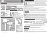
 Time Click Software version 1.02 User Manual 1 Table of Contents The purpose .................................................................................................................................. 3 The hardware ................................................................................................................................ 3 Connections ................................................................................................................................... 4 Main screen ................................................................................................................................... 4 Configuration menu ...................................................................................................................... 6 0 ‐ Operation Mode ................................................................................................................... 6 FIXED ..................................................................................................................................... 6 RANDOM ............................................................................................................................... 6 SENSOR .................................................................................................................................. 6 MANUAL ................................................................................................................................ 6 1 ‐ Metering ............................................................................................................................... 7 2 ‐ Bulb mode ............................................................................................................................ 7 3 ‐ Mirror lock ............................................................................................................................ 7 4 – Bracketing ............................................................................................................................ 8 5 ‐ Photo delay .......................................................................................................................... 8 6 ‐ Shutter delay ........................................................................................................................ 8 7 ‐ Select preset ......................................................................................................................... 9 8 ‐ Rename preset ................................................................................................................... 10 9 ‐ Reset preset ....................................................................................................................... 10 Operation .................................................................................................................................... 11 2 The purpose The objective of this device is controlling DSLR cameras through the remote connector. There are four different modes of operation: •
•
•
•
Fixed – can be used to make time lapse photos Random – the interval between photos are random Sensor – react’s to a sensor input to take a photo Manual – used as remote trigger Beyond the mode of operation, there are some additional features that can be used to enhance the device operation: •
•
•
•
Bulb Mirror lock Exposure bracketing 12 presets to store different sets of configurations The hardware Basically, this device was assembled around a microcontroller from Atmel that control all operations. It was assembled inside a box from an SAIT tape. Communication between the device and the user are made using the 16x2 LCD and in the opposite direction, through a four keys keyboard: MENU, (‐), (+) and ENTER. Opening the box, we can access the battery compartment (6 AAA batteries), adjust the LCD contrast in a potentiometer and access microcontroller programming interface (ISP) for firmware upgrade. 3 Connections There are 3 different connectors on the back of the device: •
•
•
Mini jack 2.5mm – remote, connect to camera with the appropriate adapter Mini jack 3.5mm – sensor input Power jack – for use with external 9V power supply Along with all this connectors, there is also a power switch. Regarding the remote connector on DSLR cameras, despite the fact that it assumes different types even among the same manufacturer, generally they all work the same way. Usually use 3 pins, one for GND, one for metering & focus (half shutter press) and the other for shutter operation. When you short one of these two pins to the GND pin, the respective action is taken by the camera. All connections should be made with the device powered off. Main screen Once the device is powered, the first screen shows information about the device and software version: 1.02 in this case. One second after, the device enter in normal operation mode. Since all configurations are stored in EEPROM, all options will be exactly the same that were when the device was last powered off. During the startup, if the user press and hold the enter key, it will be asked for the factory reset option. If enter is pressed again, all configuration in EEPROM will be reset for default values. For save battery power, after 10 seconds of keyboard inactivity, the LCD backlight is turned OFF. To turn it ON again, just press any of the four keys. 4 Depending on the configured mode, the main screen will look different: Fixed mode In this case with metering active and counting down 9:59 to next photo. Random mode With metering active and counting down 3:52 to next photo. Sensor mode With mode set to RISE, mirror lock active and without loop (waiting for user). Manual mode With metering active and waiting for the user to press enter. Here is the explanation of all this information on the main screen: Battery level is a graph that represents the capacity of the battery. In this case is full. Sensor mode is represented as an arrow up for a rise of sensor value through the detection value (trigger) or an arrow down for a fall. Operation mode indicate current mode with the first character of mode: F, R, S and M. Active profile is the active profile indicator: 1, 2, 3, 4, 5, 6, 7, 8, 9, A, B and C. The message area, depending of active mode, show important information to the user. Metering mode indicate if metering is active (F in white) or inactive (F in black). Bulb mode indicate if bulb is active (B in white) or inactive (B in black). Mirror lock mode indicate if mirror lock is active (L in white) or inactive (L in black). Exposure bracketing mode indicate if metering is in camera mode (C in white), is in auto mode (A in white) or inactive (E in black). 5 Configuration menu Being in the main screen, if the user press MENU it enter in configuration mode. Inside the menu, keys (+) and (‐) are used to change values, MENU is used to cancel or return to previous parameter and ENTER is used to accept or move to next parameter. The main menu is divided in ten options: 0 ‐ Operation Mode In this option, the user can choose the desired operation mode. Just press ENTER on this option and then choose the desired option using the keys (+) or (‐). After choosing an option, the user will be prompted for related parameters. FIXED Fixed operation mode Chose the fixed duration between photos in the format hh:mm:ss RANDOM Random operation mode Chose the maximum random duration between photos in the format hh:mm:ss SENSOR Sensor operation mode How the sensor is triggered; when RISING or when FALLING Value for trigger action. The arrow indicates selected mode and the second value is the current sensor reading. Amount of time in milliseconds to delay after sensor detection. If OFF, ask user to continue after a sensor detection, otherwise, reengage continuously. MANUAL Manual mode Requires no additional parameters. 6 1 ‐ Metering No metering is made before photo is taken. Meter and focus (if not in manual focus) before photo taken. Delay in milliseconds between metering and taking the photo. 2 ‐ Bulb mode Bulb inactive. Bulb active. Duration of bulb in hh:mm:ss 3 ‐ Mirror lock No mirror lock. Lock mirror before taking the photo. Usually after mirror lock, if the shutter isn’t released in the next 30 seconds, the mirror returns to initial position. This value in format hh:mm:ss helps the device to relock the mirror in sensor mode with Loop set to ON. 7 4 – Bracketing Bracketing exposure inactive. Bracketing exposure active. Delay in seconds between bracketed exposures. A higher value here may be needed low light camera bracketing. Number of frames of the bracketed sequence. In CAMERA mode, the camera must be set to bracketing and control the exposure. In AUTO mode is the device that controls the exposure. The camera must be set to BULB. Step for exposure between bracketed frames in ½ EV. Range between 1 and 8 (½ EV .. 4 EV). The duration of the first exposure. Range from 1/125 to 16 minutes but the lower values are very camera dependant. 5 ‐ Photo delay After a photo has been taken this value in milliseconds are delayed. 6 ‐ Shutter delay This value is very camera dependant and is the time it needs to detect that the shutter pin is shorted to GND. 8 7 ‐ Select preset The default profiles values are pre configured for some common types of use. Of course the user can customize them as they wish. Here is the list of what is configured: For time lapse in random mode, very good for party’s. For use as a remote trigger. For short bracketed exposures controlled by the camera. For longer bracketed exposures controlled by the camera. For bracketed exposures controlled by this device to use indoor. For bracketed exposures controlled by this device to use in dark environments. For use with a vibration sensor to capture drops falling into a glass. For use with a light sensor to catch lightning’s. For use with a sound/vibration sensor to catch balloons explosion. Without defined function and set with default values. For time lapse photos with interval of 10 minutes. For time lapse photos with interval of 1 minute. 9 8 ‐ Rename preset In this option, after pressing ENTER, each character can be edited. 9 ‐ Reset preset This option allows the user to reset the current profile configuration to the default values. The user is asked for confirmation. 10 Operation Under normal operation in modes FIXED, RANDOM or MANUAL, there are some different screens that appears to the user when a photo is taken. In case metering is active, this message appears when metering is being done. If mirror lock is active, when the device locks the mirror, this message appears. When the shutter is open, this message is shown. In bracketing CAMERA mode, this is the information shown: First exposure running. Second exposure… And finally the third exposure. In auto bracketing mode, the exposure duration is also shown: First exposure ½ of a second. Second exposure, 1 second. Fourth exposure, 4 seconds. Fifth and last exposure, 8 seconds. Third exposure, 2 seconds. 11 In sensor mode there are four possible stages: When the device first enters to sensor mode, if the sensor reading is already in the trigger zone, show his value and wait it came out. When the sensor reading is out of the trigger zone, it is ready for action. Then, if a sensor reading falls into the trigger zone, signal it and take a photo. If sensor loop is OFF, user action is required to continue. 12