1
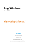
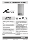
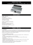
STROBE/POSITION LIGHT SYSTEM WITH POP-IN STROBE BULBS AND PROGRAMMABLE XPAK604X-HR STROBE DRIVER USER MANUAL AND INSTALLATION INSTRUCTIONS NOTICE : ALTHOUGH DESIGNED AND BUILT IN ACCORDANCE WITH THE FARs, THIS SYSTEM HAS NOT BEEN EVALUATED BY THE FAA AND IT IS NOT APPROVED FOR INSTALLATION ON CERTIFIED AIRCRAFT. WARNINGS 1. Although the XPAK strobe driver is designed to work with any voltage between 10 and 28 volts, the LED position light circuit requires at least 13.8 volts to reach full brightness, and it can be damaged by any voltage exceeding 15 volts. Always use a circuit breaker in line with the power supply. A 15 AMP fuse is already built-in the driver, but a 2-Amp fuse or circuit breaker is needed for the LED position light power supply line. 2. Like in all xenon-discharge strobe systems, high voltage (UP TO 450 VDC) is generated by the strobe supply driver and is carried to the strobe heads through the connecting cables. High voltage electrical current is capable of producing serious injury and/or death. ASSEMBLY AND HANDLING OF THE UNIT MUST BE ATTEMPTED ONLY WITH POWER DISCONNECTED. WAIT THREE MINUTES AFTER SHUTOFF BEFORE HANDLING THE UNIT AND/OR CONNECTING OR DISCONNECTING THE CABLES. “GS-AIR, a Division of GS Developments, LLC” DECLINES ANY IMPLICIT OR EXPLICIT LIABILITY FOR ANY INJURY OR DAMAGE RESULTING FROM IMPROPER CONNECTION, INSTALLATION, OPERATION OR HANDLING OF THIS LIGHT SYSTEM AND ITS COMPONENTS. GS-AIR LIABILITY IS LIMITED TO REPLACEMENTS OF DEFECTIVE PARTS OR REFUND OF PURCHASE PRICE FOR ITEMS UNDER WARRANTY.OPERATION OF THIS EQUIPMENT IMPLIES ACCEPTANCE OF THESE LIABILITY LIMITATIONS. NOTE: The XPAK strobe driver sold by GS-Air is a specially engineered unit with custom-adjusted internal clock (hence the –HR suffix, or Half-Rate). Out of 15 possible flash patterns, the SINGLE ALTERNATING, DOUBLE ALTERNATING and TRIPLE ALTERNATING flash patterns are recommended. WINGTIP UNIT INSTALLATION When you first pull a wingtip unit out of the box, you may see a clear silicon squeeze-out between the clear dome and the white base. This is to waterproof the dome/base junction. Pass your fingernail along the edge to remove the excess squeezout before beginning installation. NEVER OPEN THE WINGTIP LIGHT UNITS. 1. Set your airplane with the same attitude it will have in straight and level flight. 1 2. Draw a 5-½” long HORIZONTAL line on each wingtip in the location you choose to install your wingtip lights. Beginning from the forward end of this line and measuring aft, put a mark at 1-¼”, one at 2-7/16”, one at 3-15/16”, and one at 4-7/16”. Drill a 1/8” hole at the front and rear mark location, and drill an 1-1/8” and a 11/16” hole at the second and third (from the front) mark locations. See drawing for clarification. 1-1/8” 1. If your wing is solid-core (e.g. composite plane), make the 1-1/8” hole at least 1 inch deep to leave room for the AMP connector. You may enlarge the 1/8” holes to flox the locknuts inside, so as to build a “hardpoint” for better fixation. Then use RTV to secure the base of the wingtip unit to the wing and to waterproof the wing/light interface. 2. If your wing is metal sheet or you have a thin conposite wingtip you may use two 4-40 locknuts to further secure the wingtip light by the stainless steel screws. Turn the locknuts, not the screws (the screws are already tight against the dome). Hold the screws still with a phillips head screwdriver while tightening the locknuts. Do not overtighten the locknuts. Don’t forget to use RTV to secure and waterproof your installation. 3. Waterproof the screw heads on the top of the clear dome using a dab of clear RTV. IMPORTANT: CAREFUL AND UNIFORM APPLICATION OF RTV IS NEEDED TO WATERPROOF YOUR INSTALLATION AND TO HELP HOLDING THE WINGTIP UNIT. IF WATER OR MOISTURE COLLECTS INSIDE THE UNIT, IT MAY CAUSE MALFUNCTION. STROBE BULB INSTALLATION/REPLACEMENT This wingtip unit uses EZHIDE strobe bulbs assemblies from NOVA electronics. They can be easily installed/replaced in few minutes. 1. Open the EZHIDE bulb box, extract the bulb holding it by the black rubber base. DO NOT TOUCH the bulb with your fingers. 2. Insert the bulb in the hole in the bottom of the wingtip unit and gently work it in until the groove in the black rubber locks in place. 3. Make sure that the black edge INSIDE the wingtip is flush with the white silicon holding the base of the bulb. Also make sure that the bulb is aligned along the longitudinal axis of the wingtip unit. 2 WINGTIP UNIT ELECTRICAL CONNECTIONS Strobe connector (AMP) LED power supply wires STROBE DRIVER INSTALLATION: FOLLOW ALL INSTRUCTION INSIDE THE STROBE DRIVER BOX FOR THE CORRECT INSTALLATION AND PROGRAMMING PROCEDURE Mount the strobe power supply in an appropriate location inside the fuselage. Try to avoid proximity to radio equipment and antennas. Do not place the STROBE DRIVER UNIT OR THE CONNECTING CABLES near heat sources. Because of the heat generated by the strobe bulbs, DO NOT KEEP the strobes flashing when the aircraft is on the ground. LED power: If your aircraft voltage regulator output exceeds 14.2 volts at cruise RPM, connect a 1N4007 diode in series with each wingtip’ LED power line. This will cause a 0.6 volt drop in the LED power line and protect the LED circuitry from overvoltage damage. Call GS-Air customer support if you have any questions abouth this issue. LED-LIGHTS GENERAL SPECIFICATIONS: Power 12 – 14.5 VDC (optimal for LEDs 13.8 to 14.5 Volts) Nav light current 0.4 – 0.6 Amp for each wingtip Weight of each LED wingtip unit 2.5 oz. Stobe bulbs life 3 X 10⁶ flashes Housing material for wingtip units Fire-retardant, UV-stabilized Polycarbonate (dome) Fire-retardant ABS (base plate and chromed reflectors) Red LEDS output (color: = 630 nm) Green LEDs output (color: = 525 nm) White LEDs output (color: x=0.31, y=0.32) 14,000 millicandles each X 14 16,000 millicandles each X 14 22,000 millicandles each X 8 (each wingtip). GS-AIR, A DIVISION OF GS DEVELOPMENTS, LLC 1301 Circle Ave, Albert Lea, MN 56007 1-507-383-3516 www.gs-air.com 3 STROBE CABLE ASSEMBLY Your light system comes with approx 36 feet of strobe cable, 2 male + 2 female AMP connectors and 6 male + 6 female AMP crimp-on pins. The cable contains 4 insulated wires (red, white, black and green), one non-insulated (naked) wire and one yellow plastic filament that does not serve any purpose. STEP 1: Cut the strobe cable in two, strip the external insulation for about 6-7” on each extremity. Bend the green and the naked wire backwards, and cut the red, black and white wire so as to leave about 1” lenght. Strip the red, black and white wire insulation off for NOT MORE than 1/8”. See Fig. 1. STEP 2Crimp the appropriate pins on the RED, BLACK and WHITE wire on each extremity: female pins go to the wingtip unit, male pins go to the strobe driver; slide a segment of heat-shrink tubing over the cable end before you insert the pins in the appropriate connector. See Fig. 2. Slide the cables in your wing conduits, keeping the female pins towards the wing tips. Install the white nylon connectors over the pins. CAREFUL, the white connectors are polarized and they are different (males and females), check with the connectors already installed in the strobe driver and read the instructions in the strobe driver box. Use the green and the naked wires to power the LED NAV/POS lights. In the wingtips, connect the green wire from the cable to the red wire in the wingtip light unit, and connect the naked wire from the cable to the black wire in the wingtip light unit. In the fuselage, connect the two green wires together and then connect them to + 12 V though a FUSED switch or 2-Amp circuit breaker. In the same way, connect the two naked wires together and then connect them to the airframe ground. 4