1
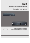
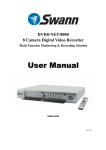
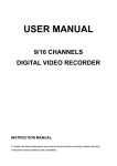
DVR-3600
User’s Manual
http://Platinum-CCTV.com
With IR Remote Control & USB Backup (All Models)
With Network Remote Viewing (All Models)
With CDRW Drive for CD Backup
Please read instructions completely before operation and retain manual for future reference
Platinum-CCTV DVR v1.0
Safety Precautions
The lightning flash with arrowhead symbol, within an equilateral
triangle, is intended to alert the user to the presence of insulated
dangerous Voltage within the product s enclosure that may be
sufficient magnitude to constitute risk of electrical shock to persons.
The exclamation point within an equilateral triangle is intended to
alert the user to the presence of important operation and
maintenance (servicing) instructions in the literature accompanying
the appliance.
Attention: installation should be performed by qualified service
Personnel only in accordance with the National Electrical Code or
applicable local codes.
Power Disconnect. Units with or without ON-OFF switches have
power supplied to the unit whenever the power cord is inserted into
the power source; however, the unit is operational only when the
ON-OFF switch is the ON position. The power cord is the main
power disconnect for all unites.
CAUTION: Danger of explosion if battery is incorrectly replaced.
Replace only with the same or equivalent type recommended by the
manufacturer. Dispose of used batteries according to the
manufacturer ¯ si nstr ucti on
Warranty
and Service
During the warranty period (one year for Hard Disk), we will repair or
replace the hard disk free of charge.
Be sure to have the model number, serial number and vendor stick
on hard disk for service representative.
About this document
Before installing stand alone DVR, be sure to thoroughly review and follow the instructions in
this Users Manual. Pay particular attention to the parts that are marked NOTICE.
Also, when connecting with external application, first turn the power OFF and follow manual
instruction for appropriate installation.
2
16 Channel Digital Video Recorder User s Manual
Before reading this document
1. This document is intended for both the administrator and users of stand alone DVR Model.
2.This manual contains information for configuring, managing and using stand alone DVR
Model.
3. To prevent fire or electrical shock, do not expose the product to heat or moisture.
4. Be sure to read this manual before using stand alone DVR Model.
5. For questions and technical assistance of this product, contact your local dealer.
Strong recommendation on installation of the DVR unit
1. Check electricity at the place you want to install the DVR unit is stable and meets our
electricity requirements.
Unstable electricity will cause malfunction of the unit or give critical damage to the unit.
2. Several chips on the main board of the DVR unit and hard disk drive inside the unit
generate heat, and it must be properly discharged.
Do not put any objects just beside exhaust port(fan) on the left side of the unit and do not
close up an opening (fresh air in-take) on the right side of the unit..
3. Put the DVR unit at well-ventilated place and do not put heat-generating objects on the unit.
When it is installed inside 19 inch mounting rack together with other devices, please check
built-in ventilation fan of the rack is properly running.
3
CONTENTS
1. FEATURES AND FUNCTION
.
2. UNIT DESCRIPTION OF FRONT PANEL.
3. REAR PANEL AND SYSTEM CONNECTION
..
.6
..
8
4. REMOTE CONTROL
5. SYSTEM SETUP
..5
12
.
5.1. SETUP MENU.
..
..12
..
12
5.2. SYSTEM SETUP
14
5.2.1. TIME/DATE SET
.
...14
5.2.2. HDD FORMAT SET
15
5.2.3. FACTORY RESET
.15
5.3. DISPLAY SETUP
..
5.3.1. CAMERA NAME SET
..
5.3.2. COLOR SET.
5.3.3. AUTO SEQUENCE SET
16
16
..
...
17
5.4. RECORD SETUP
.18
5.4.1. AUDIO CH SET
5.4.2. REC CH SET.
5.5. NETWORK SETUP.
17
19
..
19
.20
5.5.1. N/W ENABLE SET
21
5.5.2. MAC SET
21
5.6. SENSOR SETUP
5.6.1. MOTION AREA SET
21
22
5.7 SCHEDULE SET
23
5.8. USB BACKUP
24
5.9. STORAGE INFO
24
5.10. PROTOCOL SET
25
6. USER S GUIDELINE
25
7. USING THE NETWORK VIEWER
30
4
16 Channel Digital Video Recorder User s Manual
1. FEATURE AND FUNCTION
Video input: 8/16channels; Video output: 3channels.
Audio input: 4channels; Audio output: 2channels.
16 alarm input and 1 relay alarm output.
Compression mode: M-JEPG.
Support network view.
Support USB backup.
Compatible with NTSC and PAL format.
Support zooms, auto function, watermark security.
Four optional levels of image quality: very high, high, normal, low. Record and playba
ck frame rate changeable for recording.
Support alarm recording, time recording.
Support loss and motion detection functions.
Multi-function searches: be able to distinguish different alarm records and time records
from ordinary records; be able to search by time, by segment or by event.
Support various playback modes: pause, several fast forward and backward play mod
es.
Equipped with remote device and PTZ control enables (RS485).
Triplex operation can play back and search while it is recording.
480frame (NTSC, PAL is 400) per second for view, 120frame (NTSC, PAL is 100) per
second for recording.
One ATA-100 Hard Disk Interface, support Over 200G Byte.
5
2. UNIT DESCRIPTION OF FRONT PANEL
2.1 Recording/Playing Control Buttons Area
1. REC: It is manual recording button. Push this button to record video to hard disk, Re-push
this button, it will stop recording. So, this button is the switch button of manual recording and
stopping recording operation, recording and stop will work simultaneously on 16 channels. This
button doesn t work in schedule mode.
2. PLAY: Push this button to start playing the video stored in hard disk, Re-push this button, it
will stop playing. So, this button is the switch button of playing video and stopping playing
operations. Play and stop will work simultaneously on 16 channels. This button doesn t work while
time recording and alarming recording.
3. REW: fast backward button. Push this button to start fast backward playing till push play
button to start normal playing.
4. FORWARD: fast forward button. Push this button to start fast forward playing till push play
button to start normal playing the fast forward has five speeds; each time you push the button will
change the speed from slow to fast and then back to slow.
5. MODE: mode change key, push this key to change to shift mode, RE-push to change to
normal mode.
2.2 Function Control Area
1. Auto/1: Auto key, in shift mode, push this button, The DVR will be in auto dwell state, it dwells
6
16 Channel Digital Video Recorder User s Manual
according to the time set in auto sequence set menu, you can set the dwell time of each channel.
Push this button to quit this mode. If not in shift mode, push this button to see big picture of
channel 1. While inputting numbers, this button is used as number key of 1 .
2. Zoom/2: Zoom key, in shift mode, push this button, the DVR will be in zoom mode, please refer
to zoom operation in user guideline for details, push zoom button again to cancel zoom operation.
If not in shift mode, push this button to see big picture of channel 2. While inputting numbers, this
button is used as number key of 2 .
3. USB/3: USB key, in shift mode, push this button, the DVR will start USB backup, please refer to
USB backup operation in user guideline for details, push USB button again to cancel
USB backup. If not in shift mode, push this button to see big picture of channel 3, while inputting
numbers, this button is used as number key of 3 .
4. Display/4: Display key, in shift mode, push this button to display current information on the
screen, push again this to clear the information display. If not in shift mode, push this button to
see big picture of channel 4. While inputting numbers, this button is used as number key of 4
5. Freeze/5: Freeze key, in shift mode, push this button, the DVR will be in freeze mode, please
refer to freeze operation in user guideline for details, re-push this button to quit freeze mode, If not
in shift mode, push this button to see big picture of channel 5. While inputting numbers, this
button is used as number key of 5 .
6.WM/10+: Watermark button, In shift mode, if the DVR is playing video, you can push this button
to see the watermark of the picture, if the video was recorded by this DVR and has not be
changed, there will be a watermark symbol in each picture, push watermark key again to clear the
display. If not in shift mode, push this button and then push 1 to 6 to see big picture of channel 11
to channel 16.
7. Schedule/6: Schedule key, in shift mode, push this button to enter schedule state, if the DVR is
in schedule state, there will be a S symbol on screen, push again this button to quit schedule
mode. If not in shift mode, push this button to see big picture of channel 6. While inputting
numbers, this button is used as number key of 6
8. ADD/7: Add key, push this button to see big picture of channel 7. When in system setup menu,
this is an increase button. While inputting numbers, this button is used as number key of 7 .
9. DEC/8: Decrease key, push this button to see big picture of channel 8. When in system setup
menu, this is a decrease button. While inputting numbers, this button is used as number key of 8 .
10. SR/9: Single frame rewind button, in shift mode, while in playback state, long press this button
can see single frame rewind, press play button to play normally. If not in shift mode, push this
button to see big picture of channel8.while inputting numbers, this button is used as number key
of 9 .
11. SF/0: Single frame forward button, in shift mode, while in playback state, long press this
button can see single frame forward, press play button to play normally. If not in shift mode, push
7
this button to see big picture of channel 10.while inputting numbers, this button is used as number
key of 0 .
12. Search/Menu: push this button to enter search menu, please refer search play in user
guideline for details. Long press this key to enter menu (need password), in menu setup, push
this key to quit current menu.
2.3 Channel Choosing Control Area
1. Four picture/up: Push this button to see full screen, re-push
this button to see the next channel. While selecting menu items,
push this button to move up the cursor.
2. Sixteen picture/right: Push this button to see sixteen
pictures display, re-push this button to see thirteen pictures.
While selecting menu items, push this button to move the cursor
rightward.
3. Big pictures/down: Push this button to see four pictures
display, re-push this button will display next four pictures. While
selecting menu items, push this button to move down the cursor.
4. Nine pictures/left: Push this button to see nine pictures display, re-push this button to see
eight pictures. While select menu items, push this button to move the cursor left ward.
5. Enter: While selecting menu items, push this button to select the item. While playing video,
push this button to pause the play, push play button to continue play.
3. REAR PANEL AND SYSTEM CONNECTION
2
CH1
CH2
CH3
CH4
CH5
CH6
CH7
CH8
9
IN
OUT
1
2
ALARM & RS485
OUT
WAN
USB
CH9
CH10
CH11
CH12
CH13
CH14
CH15
CH16
OUT S VIDEO 3
4
DEBUG
OUT
DC 12V
INPUT
AUDIO
1
3
4
5
6
7
8
10
11
3.1 Back panel and connection terminals
The power cable and input, output signal terminals are all at the back of the machine, The
connection to monitor, camera etc equipments are all carried out through the terminals and
sockets on the back panel .the back view of the machine is illustrated as below.
Each part of the back panel is illustrated as below:
1.video input 1-16 2.main output 3.assistant monitor 4.S-VIDEO 5.audio input 6.audio output
7.net interface 8.USB port 10.debug port 11.power 9.Alarm and RS485port define:
8
16 Channel Digital Video Recorder User s Manual
1-12: sensor 1-sensor 12; 13, 20, 24, 25: GND, 14-17: sensor 13-sensor16, 18: RS485A 1
9: RS48521: COM 22: NC 23: NO
3.2 Video and Audio Connection
The DVR can support up to 16 cameras video input at the same time.
Main
Out
Video In 1
CH1
Assisant S Video
Out
Out
Video In 16
CH2
CH3
CH4
CH5
CH6
CH7
CH8
IN
OUT
1
2
OUT
CH9
CH10
CH11
CH12
CH13
CH14
CH15
CH16
OUT S VIDEO 3
4
AUDIO
Microphone
The DVR can connect 4 channel s audio input, but you can only select one for recording. To
display the DVR picture, the DVR video output signal should be transferred to your TV set or
monitor. Any TV set that has a video input terminal is suitable for displaying the image. The
figure above shows the video and audio signal line connection.
Note: at one time, you can only connect one audio input, which means, if you connect a
n audio to CH1, you cannot connect any CH2 to CH4.you should plug them out.
3.3 Alarm Connection
The DVR can support up to 16-alarm input and 1 alarm output.
Alarm input: there are two types of alarm input.
1. Voltage output (5V and 0V)
A: In case sensor output high voltage (5V) normally and output low voltage when trigg
ered (0V), then users must set DVR as low voltage alarm.
B: In case sensor output low voltage (0V) normally and output high voltage when trigg
ered (5V), then users must set DVR as high voltage alarm.
Please refer to the picture below, channel 2 to channel 16 are the same as channel 1.
13
12
25
11
24
10
23
9
22
8
21
7
20
6
19
Sensor Ch1
9
5
18
4
17
3
16
2
15
1
14
2. Open/Close output
A: N.O. Normal open, close when triggered. DVR must set as low voltage alarm.
B: N.C. Normal close, open when triggered. DVR must set as high voltage alarm.
Please refer to the picture below, channel 2 to channel 16 are the same as channel 1.
13
12
25
11
24
10
23
9
22
7
8
21
20
6
19
5
18
4
17
3
16
2
15
1
14
Switch Ch1
Alarm output:
There are three alarm output pin, the status of these pin are illustrated as below
N. O .
N. O .
COM
N. C .
COM
N. C .
There is an example for alarm output connection
N. O .
Ala rm
C OM
N. C .
5V
10
16 Channel Digital Video Recorder User s Manual
3.4 Hard Disk Connection
There are processing to install the hard disk.
Note: If the DVR comes with a HDD, skip the following steps.
1. Push out the hard drive rack from the
2. Open the top cover of the drawer.
DVR side panel.
3. Jump HDD to Master
4. Connect the ribbon cable (IDE) cable &
power cable.
Jump to Master
5. Close the top cover of the drawer and
put the hard drive drawer back into the
DVR
11
6. Lock the hard drive draw by turning the
key clockwise
If you have another HDD, please jump that HDD to SLAVE, and open the machine, put
the HDD to the HDD shelf, and then connect the power and digit cable
4. REMOTE CONTROLLER
0
9, 10+: Select the channel (Full screen)
2x2: 2x2 Screen Mode
3x3: 3x3 Screen Mode
4x4: 4x4 Screen Mode
USB: USB Storage Backup
AUTO: Auto Sequence Mode
ZOOM: 2X Zoom
FREEZE: Freeze
DISPLAY: Hard Disk Information
MENU/EXIT: System Setup
SEARCH: Time Search, Event Search and Start Stop Search
ENTER: Enter Next Menu
REC: Record
WM: Watermark set
PTZ: Control Speed dome
5. SYSTEM SETUP
Before using the video recorder, the first step is to set up the system according to user s needs;
otherwise the machine will run with the default settings.
5.1 SETUP MENU
When in setup mode, push upward button or downward button, the cursor will move among
the settable items, continuous pushing will make the cursor move among
the
options one
by one, and it can recur. The selected one will display in yellow color.
While choosing digital fields, e.g. year, month, day, hour, minute, second etc, push
leftward button or rightward button, the cursor can move leftward or rightward among
The several digits of one field, continuous pushing will make it move among digits one by
one,
and it can recur.
12
16 Channel Digital Video Recorder User s Manual
Please push leftward or rightward button to change the value that the cursor on,
push ° ENTE ¡ ± but t on t enter sub menu and push menu button to return to previous menu.
Long press the menu/search button on the keyboard or press the remote controller to enter
the Setup Main Menu.
You can show password input box according setting of password set.
If
you fault password input 3-times, then you can ¯t ent er t he set up menu.Default password is ° 000 ¡±
If you enter the correct password, the main menu will display ad below.
13
5.2 SYSTEM SETUP
Push ENTER button to enter sub menu
PLAY REPEAT: Set the Playback Repeat
VIDEO SYSTEM: Set the NTSC/PAL
BUZZER SOUND: Set the Buzzer On/Off
5.2.1 TIME/DATA SET
Set the date and time.
DATE: Set the date
TIME: Set the time
FORMAT: Set the time display format (USA, EURO and Asia Users)
DISPLAY: Set the time display on/off
LOCAL: Set the time display position
14
16 Channel Digital Video Recorder User s Manual
5.2.2 HDD FORMAT SET
Format the hard disk.
Select YES , to format the hard disk. And all video on the HDD will loss.
5.2.3 FACTORY RESET
Initialize all the setup; the DVR will reset to default.
15
5.3 DISPLAY SETUP
BOUND COLOR: Set the Color of Video Boundary (BLACK / WHITE / GRAY).
BLANK COLOR: Set the Background Color of Loss Video (BLACK / WHITE).
5.3.1 CAMERA NAME SET
When the cursor moves to camera name, please push enter button, the camera name
setup window will appear, which is illustrated as below.
Each channel s name is the combination of eight characters. Push upward or downward
button to select each character, push rightward or leftward button to modify each character, and
then push enter button to save this name.
16
16 Channel Digital Video Recorder User s Manual
5.3.2 COLOR SET
When the cursor moves to color set, please push enter button, the Color setup window will
appear, which is illustrated as below.
CON: picture contrast
BRI: picture brightness
HUE: picture hue
SAT: picture saturation
5.3.3. AUTO SEQUENCE SET
Set the Display Time of Auto Sequence. Please push enter button, the auto sequence setup
window will appear, which id illustrated as below.
17
Set the time of the relevant channel. Time can be set in the range from 0 to 99 seconds.
5.4 RECORD SETUP
OVER WRITE: if set to YES , the DVR will automatically overwrite the HDD from the beginning
when the HDD is full. If set to NO , the DVR will automatically stop recording when the HDD is
full. If there are two HDD in the DVR, when the MASTER HDD is full, the video will store to the
SLAVE HDD, and when the SLAVE HDD is also full, the DVR will overwrite the MASTER HDD if
set this to yes, otherwise it will stop recording is set to no.
REC SPEED: the recording frame rate of the DVR, factory default setting is 30F/SEC for NTSC
(25F/1SEC for PAL), Which means DVR records the events at the speed of 30 shots of frames
per second, The higher the record frame rate, the more natural look will be displayed on the
screen when you playback. The lower the record frame rate, the more you can save the space on
the hard disk. The highest frame rate is 120F/SEC (PAL us 100F/SEC) when the resolution is in
320 sizes.
REC QUALITY: There are four different video quality settings: VERY LOW, LOW, NORMAL,
HIGH and VERY HIGH. The higher the video quality, the clearer images when you playback. The
lower the video quality, the more you can save the space on the hard disk drive.
RESOLUTION: The record picture size of the DVR, there are two modes: 360 and 720, default is
360. In 720 mode, the record picture is twice bigger than is 360 mode, in 320 mode the REC
speed is 120F/SEC
PAL is 100F/SEC
and the maximal REC speed in 720 mode is
60F/SEC(PAL is 50F/SEC).
PB SPEED: The frame rate of playback, default is NO USE, which means the same as record.
18
16 Channel Digital Video Recorder User s Manual
5.4.1 AUDIO CH SET
When the cursor moves to audio CH Set, please push enter button, the audio CH setup window
will appear, which is illustrated as below.
There are four audio input channels, for each channel you can select anyone of the 16 channels.
Although there are four audio input channels, you can only record one channel s audio at the
same time, so, for the right audio set, you have to select one channel in these four channels in the
Record Setup menu.
5.4.2 REC CH SET
When the cursor moves to REC CH Set, please push enter button, the REC CH setup window
will appear, it is different for 720 size and 360 size, in 720 size, the window is illustrated as below,
push upward and downward buttons to select channel, push leftward or rightward button to
change the setting, if the channel is setting OFF, this channel will not be recorded in recording
19
mode If the re resolution is set 360 size, the REC CH Setup window is not accessible. Set Record
ON/OFF for the relevant channel.
5.5 NETWORK SETUP
When the cursor moves to Network Setup, then push enter button, the network setup menu
window will appear, which illustrated ad below is. If a PC View software from Internet is connected
to the DVR. You can t access this menu unless you disconnect the PC View.
IP MODE: the DVR has 2 IP mode, STATIC IP and DHCP, if you select STATIC IP, you have to
set the IP address manually, if you select HDCP mode, the DVR will automatically get the IP
address.
For STATIC IP, push upward or downward button to move the cursor among the digits, you can
push rightward or leftward button to modify the digits, also, when select a digit, you can push
enter button then push leftward or rightward button to select each bit of the digit, and then push
rightward or leftward button to modify the bit of this digit, push enter to save you change.
NETWORK ENV: the DVR has three types of different network conditions: LOCAL, EXTER_LAN,
EXTER_WAN, if in local network, please select LOCAL, if for internet use, please choose
EXTER_LAN, if the internet condition is not very good, please select EXTER_WAN.
VIDEO PORT: the video transmits port for the computer.
COMMAND PORT: the command transmits port for the computer.
If you change any of the VIDEO PORT and COMMAND PORT or MAC address, you have to
restart the DVR to use the net viewer software.
Note: if you have change the MAC address, you can t see the MAC ADDR SET
20
16 Channel Digital Video Recorder User s Manual
5.5.1. N/W ENABLE SET
If you set the channel OFF, this channel will not transmit to the network, so if you want to see a
channel from network, you have to set this channel on.
5.5.2. MAC SET
When the cursor moves to MAC set then push enter button. The MAC set window will appear
which is illustrated as below.
If you have more than one DVR in a local area network, you have to set each DVR to have an
exclusive MAC address, but remember that you have only one chance to modify the MAC
address, once you have changed the MAC address, this menu will not appear
5.6 SENSOR SETUP
When the cursor moves to sensor set then push enter button. The sensor set window will
appear which is illustrated as below.
21
ALARM ENABLE: alarm trigger switch, you can be set to off, NC or N.O. If users set it to off, the
DVR will ignore the alarm input.
MOTION ENABLE: motion alarm switch, you can be set to on or off. If users set it to off, the
motion alarm will be ignored.
MOTION LEVEL: motion sensitivity level, if the figure in the picture id small, please set to high of
very high, the default is normal.
BUZZER TIME: buzzer sound time when there is a sensor or motion alarm.
SENSOR RECTIME: when a motion or sensor alarm occurred, the DVR record last time, the
default is 1 minute.
Note: users should press schedule button after setting up the parameters so to activate
the settings.
5.6.1 MOTION AREA SET
Turn the Motion Block ON/OFF.
22
16 Channel Digital Video Recorder User s Manual
When the cursor moves to Alarm set, then push enter button, the alarm setup window will
appear, which is illustrated as below. Please push upward, downward, leftward, rightward button
to move the cursor and push enter button to change, long push enter change all value the same
as you selected.
5.7 SCHEDULE SET
When the cursor moves to Schedule Set, please push enter button, the schedule setup window
will appear, which is illustrated as below.
You change a recording schedule during a week using this setup, from Monday to Sunday, you
can set a period time in each day.
START: start record time
STOP: stop record time
SUN
23
SAT: Select the weekday for recording (00:00-23:59)
5.8 USB BACKUP
Set the USB BACKUP.
Plug in the USB device, and press enter button, you can see the below picture.
There are two types of backup mode: STILL and MOVIE, in STILL mode you can backup Picture
and in MOVIE mode you can backup video.
5.9 STORAGE INFO
Storage information shows the information on hard disk.
MODEL: Model Number of the Hard Disk
CAPACITY: Total capacity
USED SIZE: Space used
OVER WRITE: The number of times overwritten
24
16 Channel Digital Video Recorder User s Manual
5.10 PROTOCOL SET
Set the right protocol, you can control the SPEED DOME by the DVR.
When the cursor moves to Protocol Set, then push enter button, the protocol set window will
appear, which is illustrated as below. Push upward or downward button to move the cursor, and
push rightward or leftward to change the value.
CHANNEL SEL: select the channel that is connected to the speed dome, which you want to
control.
BAUDRATE: Can change from 1200bps to 19200bps.The default is 2400bps.
DOME ADDR: The address of the speed dome, changeable from 0x00 to 0xff.
PROTOCOL: The protocol that DVR control speed dome, include PELCO-P, PELCO-D,
NEON,LILIN, default is PELCO-P,
6. USER S GUIDELINE
6.1 start the machine
Before starting the machine, please make sure all the items in the Safety Precautions at the
beginning of this manual are fulfilled.
Before starting the machine, please check the system connection, input and output equipment
connection.
Please insure the video-recorder s input video (NTSC/PAL) and the monitor (NTSC/PAL) meet
the demands.
Start exterior equipment after checking over.
Insert the removable hard disk case to the end, and lock it up (turn right the hard disk lock);
connect the power, the machine start to work.
6.2 Turn off the Machine
Normally turn off the machine when the system shutdown, which means do not to turn off the
machine while playing or system setting up, especially not to turn off the machine while
25
recording.
Push recording button to stop recording or push playing button to stop playing or exit from
system setup menu, then turn off the power.
If do not use the video recorder for a long time, should pull out the power line from the
electrical outlet.
6.3 Normal Recording
Connect the power to all related equipments; ensure that there is video input.
Push display button to check spare space of the hard disk, if there is no much space, please
think whether to change hard disk first or select overwriting modes.
Check recording parameter setup before recording; select video quality, frame rate. You cannot
change record setting during the process of recording,
Manual recordings belong to normal recording. Under the manual mode (non-schedule status),
here pushing record button will record all channels video.
Push the record button to begin recording, sixteen channels will start simultaneously recording.
While in normal recording mode, push record button, and enter the right password, it will stop
recording.
During the process of recording, if the hard disk is full, and the system is set to automatic
overwrite, then the recording will not be interrupted, and it begins to overwrite the earliest
recorded area; if the system is set to overwrite disable, it will stop recording.
6.4 Alarm Recording
Alarm recording is not started by manually pushing record button, the entire recording started by
manually pushing the record button are normal record.
Alarm recording can be activated by alarm input signal or motion, so it must to check whether the
connection of alarm input equipment is correct, stable and reliable, and the alarm set is right,
please refer to sensor setup.
The prerequisite condition of whether the alarm recording can be activated by exterior input signal
or the motion is that the system must be set on schedule, also, in the menu of alarm setup, for
exterior input alarm, alarm enable of that channel must set to ON , for motion alarm, motion
enable of that channel must set ON , and set the right area for motion detect.
Under the state of off-schedule, system will never start alarm recording. Setting schedule on or off
is achieved through pushing the schedule button on the front panel, but not through system setup
menu and window. Under schedule-on situation, the character S will display on the screen,
Alarm video recording cannot stop by pushing record button, but can stop by removing schedule.
Because once the system is set on schedule, the schedule cannot be removed randomly, so there
is a password protection to remove schedule, only after inputting correct password, you can take
schedule off.
Check alarm recording setup before recording; confirm the video quality and the frame rate, the
26
16 Channel Digital Video Recorder User s Manual
record setting cannot change during recording process.
As long as the alarm input signal is effective, the alarm recoding continues, When the alarm input
signal loses efficacy, the time set up by A/M REC TIME becomes effective, and when the time
goes out, the alarm recording automatically stops. In course of this, if you want to manually stop
alarm recording, the only way is to remove schedule (answer the password).
6.5 Time Recording
Time recording starts and stops recording automatically according to the pre-arranged time period.
It is applied to fixed timetable, for example, the periodical work time recoding (of off time recording)
with fixed start/stop time.
To start time recording function, besides making record schedule setup beforehand, must push
down the schedule button on the front panel to set schedule on. While pushing down this button,
the schedule symbol S will display on the screen without pushing the schedule button, the time
recording parameter setup will not work.
The prerequisite condition of whether the time recording takes effective is system must be set on
schedule.
In time record state, you can push again schedule button the enter password to stop time
recording.
Because time recording is correlated closely with time, so before using this function should
previously adjust the time.
6.6 Playback
Push play button, system begins to play the images recorded
In the process of playing of fast backward playing, pushing push play button will begin normal
playing from the current place.
In the process of fast forward playing or fast backward playing, re-pushing play button can
resume play. Continuously
In the process of fast forward playing or fast backward playing, pushing push play button will
begin normal playing from the current place.
Continuous pushing forward button will change the fast-forward among five levels of speed (X2,
X4, X8, X16, X32) circularly. Circularly. Continuous pushing reward button will change the fast
backward among four levels of speed (X2, X4, X8, X16) circularly.
During playback mode, long press single frame rewind button will play backward frame by frame;
long press single frame forward button will play forward frame by frame. Push play button to play
normally.
Push again play button will stop playing.
6.7 Search play
Push search button, search play window will display on the screen.
TIME SEARCH: search play by input time.
27
EVENT SARCH: search play by event list.
START STOP SEARCH: search play by segment.
Push upward and downward button to move cursor, the push enter button to enter submenu you
select, push search button to quit from search menu.
6.8 Time search
When the cursor moves to Time Search, then push enter button, the time search window will
appear, which is illustrated as below.
Their red block means there has video at that time
Push leftward and rightward button to move the cursor among year, month, day, hour and minute,
if you select the year and push enter button you will select month and so it is with day and hour,
Push add and DEC button to modify the time. If you select the minute and that minute has a red
block then you can push enter button to play the video from that time you selected.
6.9 Event Search
When the cursor moves to Event Search, the push enter button, the event search window will
appear, which is illustrated as below.
There are four types of event list: MOTION, ALARM, SCHEDULE and NETWORK. MOTION
means motion alarm recording Alarm means sensor alarm recording, SCHEDULE means time
recording, NETWORK means network recording
Push upward and downward button to move the cursor among the event list, push leftward and
rightward button to see previous or next page, push enter button to play the segment you select.
Push search button back to Search Play menu.
If you want to change the HDD between MASTER HDD and SLAVE HDD, just push mode key,
the push enter key to change, lush menu to give up
6.10 Start Stop Search
When the cursor moves to Start Stop Search, then push enter button, the Start stop search
window will appear, which is illustrated as below.
All record segments are displayed here, push upward and downward button to move the cursor
among the segment list, push leftward and rightward button to see previous or next page, push
enter button to play the segment you select. Push search button back to Search Play menu.
If you want to change the HDD between MASTER HDD and SLAVE HDD, just push mode key,
the push enter key to change, push menu to give up
6.11 USB Backup
Plug in the USB device, go to the menu of Backup set, check that if the USB device was detected
or not, and the free space of the USB device is enough or not, select the backup mode, then quit
the menu setup.
In shift mode, if you select STILL for the backup mode in the Backup Set menu, push the USB
button, it begin to backup the main out picture to the USB device, there will be a S blinking on
28
16 Channel Digital Video Recorder User s Manual
the screen, when is tip blinking the backup of the picture is done, you can plug the USB device
out and see the picture on a computer.
If you select MOVIE for the backup mode in the Backup Set menu, push the USB button in shift
mode, it begin to backup the main out video to the USB device from the moment, push USB
button again to select the end of the backup video, there will be a A blinking on the screen, This
may take a little time, and make sure the USB device has enough free space, if blinking stops, the
backup is ok, you can see the video on a computer with net viewer software.
6.12 USB Update
Create a folder named firmware in the USB root directory, copy the update files to the folder,
Plug in the USB device, go to the menu of Backup set, check that if the USB device was detected
or not, go to the Firmware Update menu and select USB method, move to Update Start and press
enter button, update will start, if you see picture below, update is ok.
Then reboot the DVR
NOTE: do not shut down the DVR when the DVR is updating, it may cause fatal problem.
6.13 Zoom
In shift mode, press zoom button or press the zoom button on the remote controller, the DVR will
be in zoom mode, which is illustrated as below.
Press upward, downward, leftward or rightward to move the zoom area, then push enter button to
zoom, press zoom button again to cancel zoom operation.
6.14 FREEZE
Press the Freeze button on the remote controller or keyboard, on the full screen mode Press
the Freeze button to pause a screen; on the other modes, press the Freeze button to see the
Freeze menu. Here, select a channel number to freeze.
6.15 PTZ OPERATION
This DVR can control speed domes, which are connected to the DVR.
To control the speed dome, make sure all the lines are correctly connected, first you must set the
right protocol, baud rates, and speed dome s address for each speed dome, please refer to
protocol set.
PTZ can only be operated by remote controller, press the PTZ button on the remote controller,
PTZ will be display on the screen, then select 1 to 16 to choose PTZ channel, the channel
number will be displayed after PTZ . You can press upward, downward, leftward, rightward button
to move the speed dome, and press the button again or press enter to stop. If you press the IRIS
button, the character IRIS
will appear on the screen, please refer to the picture below, then you
can press the + and - button to change the IRIS, the same to control the focus, zoom, and
speed, also press enter button to stop.
Press the PTZ button one more time to exit from PTZ control.
29
7. USING THE NETWORK VIEWER
Use the PC view software, you can view the DVR through Internet, also, you can view and
backup the video information on the HDD through a computer.
Open the software; you will see the window below:
7.1 Setting
Please click
button, you will see the window below: enter the IP address and click
° O ¡ ± but t o
IP Address: Set the IP of the board
Port: Set the communication port and AV port
7.2 Viewer connect
Press
bottom, you can show login box.
30
16 Channel Digital Video Recorder User s Manual
<Connect success>
<Connect fail >
7.3 Liveplay
You can select this button to see live picture, just click the play
button.
7.4 Playback
Click Playback net search window will display. First, you have to select the HDD of the DVR.
Click the Get record list or Get event list , if the DVR has record list, you can see the window
below:
31
Double click the record list; you can see the playback video.
The event list operation is the same as record list operation
7.5 Scandisk
Connect the HDD that used in the DVR to a PC and then select Scandisk, Scandisk window will
display, click
and select one HDD, then you can play all the video on the HDD.
<Scandisk Menu>
7.6 FilePlay
Press ° Fil e Pl a button, you can see the below picture, press the open button play the video file
on the computer.
< Fileplay Menu>
7.7 Save to AVI
Save the video played on the current viewer to AVI.
32
16 Channel Digital Video Recorder User s Manual
Pressing the button, you can record
the video by you computer.
Pressing the button, you can See the
below picture.
Pressing the button, you can remote
the DVR record to the HDD.
Pressing the button, you can stop the
record DVR.
<Determine the file name and the location where the file is saved>
Click the Save to AVI button and determine the file name, the location and channels to save.
Then AVI saving will start. Click the Save to AVI once more will stop saving.
33
Main standard & parameter chart
Item
Compressed picture
Specification
M-JPEG
Video signal
NTSC/PAL
Video input
Conposite:1.0Vp-p/75 ,BNC
8/16
Video output
Conposite:1.0Vp-p/75 ,BNC
2 S-VIDEO
Audio input
-8Db 22K ,RCA connector 4
Audio output
-8Db 3K ,RCA connector 2
Alarm input
16
Alarm output
1
Record time
18-1680 hours/40G
Electron clock
Secrete function
Update
Power source
Environment temperature
weight
Exterior size
Year/Month/Day; Hour/Minute/Second
Password protection
USB
DC12V 5A
Work temperature:+5 ~+70
;humidity:<90
store temperature-20
;humidity:<95
~+70
5.3kg(include power supply)
430mmX400mmX90mm
Notice: Sorry not inform in time of any changes to the standards and exterior sizes.
34