1
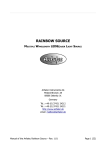
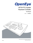
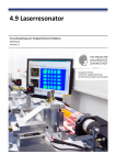
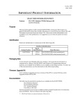
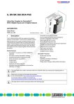
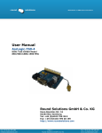
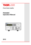
Quick Reference
Thorlabs Instrumentation
Optical Power Meter
PM100A
2009
Safety
Attention
All statements regarding safety of operation and technical data in
the instruction manual will only apply when the unit is operated
corectly.
The power meter PM100A must not be operated in explosion
endangered environments!
Sensor, photodiode and control inputs and outputs must only be
connected with duly shielded connection cables.
Only with written consent from Thorlabs may changes to single
components be carried out or components not supplied by
Thorlabs be used.
Do not remove covers!
Refer servicing to qualified personal!
Table of Content
1 2 2.1 2.2 2.3 3 3.1 3.2 3.2.1 3.2.2 3.2.3 3.2.4 3.2.5 3.3 4 2
General Information
Getting Started
Unpacking
Preparation
Physical Overview
Operation
Connecting a Power Sensor
Controlling the PM100A
Navigating the Menus
System Settings
Power Measurement
Analog Output
Battery Charging
Computer Interface
Addresses
3 3 3 3 4 7 7 7 7 7 8 11 11 11 12 1 General Information
The PM100A Handheld Optical Power Meter is designed to measure the radiant
power of laser light or other monochromatic or near monochromatic light sources.
The space-saving, battery powered design and compatibility to all Thorlabs ‘CSeries’ photodiode and thermal sensors, and custom photodiode and thermal
detectors, featured with a fast USB device interface open a wide range of
applications in Manufacturing, Quality Control, Quality Assurance, and R&D for
stationary and field use. The unit combines a precise 4 digit power readout with a
high sensitive mechanical analog needle meter to perform laser tuning tasks or
watching trends.
Please refer to the user manual on the data carrier supplied with the unit for
detailed function description.
2 Getting Started
2.1 Unpacking
Inspect the shipping container for damage.
If the shipping container seems to be damaged, keep it until you have inspected
the contents and you have inspected the PM100A mechanically and electrically.
Verify that you have received the following items within the hard-case:
1. PM100A power meter console
2. Plug-In power supply with Interchangeable primary plug for USA, UK,
Europe, and Australia
3. USB cable, type ‘A’ to ‘mini-B’
4. Quick-start guide
5. USB memory stick with instrument drivers, user application and operation
manual
6. Certificate of Calibration
2.2 Preparation
Configure the plug-in power supply with the primary plug for your local power
supply.
Connect a suitable power sensor. The sensors have a self-fixing mechanism. To
plug or unplug sensors slightly press from both sides on the brass pins in the
connector housing.
Turn the unit on by pressing the power button in the side panel.
After switching on the unit, the needle deflects to full scale and the graphics display
shows the device status and then jumps to the last measurement screen prior
powering down.
The PM100A is immediately ready to use after turning on.
3
2.3 Physical Overview
Fuction Keys:
Navigation:
Enter/Edit:
TSWX
OK
Wavelength:
λ
Relative Measure: Δ
Backlight:
Analog Meter
Needle Zero Adjust
Graphics Display
(Switch off unit prior to adjusting!)
Figure 1
On/Off Switch
Front Panel
USB Connector Sensor Connector (DB9 female)
DC Input (Charger)
Analog Output (SMA)
Figure 2
4
Side Panel
Pull here to lift the support
Figure 3
Removable protective
rubber boot
Rear View
Mounting Thread 1/4“-20
Figure 4
Bottom View
5
Power Scales
Delta Power
Scale
Power Range
Setting
Power Scale
Setting
Operating
Wavelength
4 digit Power Readout
with Units
Menu Items (Soft Buttons)
Information, Status and
Warning Indicators
Operation Overview Standard View:
Function
Menu
Key
Item
OK
W
X
R _.___ _W
Auto set Meas. Range
Range Down
Range Up
S _.___ _W
Auto set Needle Scale
Zoom In Scale
Zoom Out Scale
ZERO
TUNE ;
MENU
S T
Browse
Perform Zeroing
(No Function)
Menu
Tune Sound On/Off
Reset Maximum Power Value
Items
Enter/Exit System Menu
Switch to Statistics View
Operation Overview Statistics View:
Menu
Item
Function
Key
OK
W
X
R _.___ _W
Auto set Meas. Range
Range Down
Range Up
S _.___ _W
Auto set Needle Scale
Zoom In Scale
Zoom Out Scale
HOLD / RUN
TUNE ;
Hold / Run Statistics
Reset Statistics Values
Menu
Tune Sound On/Off
Reset Statistics Values
Items
Enter/Exit System Menu
Switch to Standard View
MENU
Figure 5
6
Display Setup
ST
Browse
3 Operation
3.1 Connecting a Power Sensor
The PM100A supports all Thorlabs ‘C-Series’ photodiode and thermal power
sensors. These can easily identified against older versions of Thorlabs power or
energy sensors by their red connector housing. The console will not recognize
sensors from the ‘A’ and ‘B’ series. Please contact Thorlabs for the upgrade of old
sensors with ‘C-Series’ connectors.
To plug or remove a sensor slightly press on the two bolts in the connector
housing, that fix it by resilience. Sensors can be ‘hot-swapped’ to the console, after
recognizing a new valid sensor the type and calibration data will be downloaded to
the console in approximately 2 seconds, and the unit is ready to operate with the
new sensor.
3.2 Controlling the PM100A
3.2.1 Navigating the Menus
The measurement screens contain of five menu items (soft buttons) that are
arranged in a column in the right of the graphics display. These can be navigated
with the up and down (ST) keys and controlled by the left and right (WX) keys
and/or the enter/edit (OK) key
The focus is always on the button in inverse presentation .
3.2.2 System Settings
After navigating to the bottom soft button MENU and confirming it with the OK key
the system menu can be scrolled with the S or T keys. To perform the initial
adjustments the settings can be edit or changed with the W or X keys on ring
controls or by using all navigation keys for numeric controls.
The menu is arranged on three pages with four lines each. The items depend on
the connected sensor. To leave the system menu press the OK key or navigate
down or up to the ‘EXIT’ item and confirm with OK.
Page 1: Measurement Settings
Bandwidth
Accelerator
Attenuation
Line Filter
Sets input bandwidth to High or Low (WX)
(only visible with connected photodiode sensor)
Enables/disables the speed up circuit (WX)
(only visible with connected thermal sensors)
Includes a filter or beam splitter for the power calculation.
The input is in dB. When an attenuation is set, the value is
displayed in the status indicator. (WXST)
Sets the unit to the local line frequency 50Hz/60Hz
to avoid aliasing effects (WX)
7
Adapter Type
Sets the PM100A into the mode to measure photo current
or thermal voltage. Please refer to the detailed user manual
for connecting a custom sensor. (WX)
Page 2: Console Settings
Shows the remote status. Press X to set the unit back to
local mode.
Backlight
Sets the brightness of the LCD and key backlight.
The setting range is 0 (off) – 100% (maximum). (WXST)
Battery Timer
The unit automatically powers off in battery operation after a
certain time without user action. This feature can be set to
10 or 60 minutes, or switched off. (WX)
The feature is inactive with connected external power
supply (AC adapter or USB)
Firmware Upload Needs to be set to ‘ON’ before uploading a new firmware
version. The function will automatically reset to ‘OFF’ after
powering down (WX)
Interface
Page 3: System Information
Console Information X Shows console related information. (WX)
Sensor Information X Shows information about the connected power sensor.
Tau
Sets the time constant for custom thermal sensors (only
visible with connected custom thermal sensor) (WXST)
EXIT
Aborts the system menu and switches back to the last
measurement screen. (OK)
3.2.3 Power Measurement
3.2.3.1 Range Control
Navigate to the topmost menu item R -.-- - W ; 6 power corresponding current or
4 power corresponding voltage ranges can be adjusted manually with the W or X
keys. Pressing the OK key the unit performs a nonrecurring auto-ranging until the
optimum range has been found for the currently measured power level. The range
control menu item indicates the particular full range value in Watts.
A permanent auto-range mode is only available in remote operation.
3.2.3.2 Scale Control
After setting the measurement range the unit automatically selects the needle
scale, where the full power range is covered. To change the needle scale navigate
to the S -.-- - W menu item. With the W or X keys the scale can be optimized to
different end scales for best readability of the power value (zoom function). This
8
adjustment can also be automated by pressing the OK key. The scale control
menu item indicates the particular full scale value in Watts.
The scales end have a fixed 1 – 2 – 5 grid, therefore it is possible that the full scale
range may be higher than the power range. In such a case, when the power level
is exceeding the power range, the needle will deflect to the right stop and the
readout value will indicate ‘HIGH’.
3.2.3.3 Wavelength Correction
λ
Pressing the λ key leads to a wavelength menu with 8+1 individually configurable
sensor independent settings. The currently set operating wavelenght is indicated
by a following arrow () and has focus when entering the menu. Select the
desired operating wavelength by navigating with the STWX keys and confirming
with OK. The λ key allows to exit without changing the operating wavelength.
To preconfigure or edit a wavelength item, navigate to it and keep the OK key
pressed until the last digit gets underlined. Set the desired wavelength with the
STWX keys and confirm with OK.
When selecting a wavelength that is not applicable for the connected sensor a
warning sound will appear and the unit will keep the previous wavelength setting.
Wavelength setting in remote operation will overwrite the down to the right value.
3.2.3.4 Zeroing
Confirming the ZERO menu item with OK, the unit performs an automated zero
adjustment and from now on takes into account this zero level for the power
readout calculation. This feature is used to zeroing thermal sensors, performing
dark current adjustment on photodiode sensors or suppressing small ambient light
levels. When the initial power level is too high, a failure message will appear that is
prompting to cover the power sensor prior to zero adjustment.
When the PM100A detects “negative” power levels, additionally a ZERO! warning
will appear in the status indicator.
9
3.2.3.5 Tune Sound
The TUNE; menu item switches on and off an audible tone for laser tuning
support. The intermitting tone will increase its repetition rate up to a permanent
sound at the maximum reached power level. When the Tune feature is activated,
the maximum level is indicated instead of the operating wavelength. To reset the
maximum power level to the actual level press one of the W or X keys.
Leaving the focus of the TUNE button or pressing OK will stop the sound.
Sound On/Off: OK
Reset max level: W X
S = maximum power level
3.2.3.6 Relative Measurements
Δ
The Δ key switches on and off the relative measurement mode.
The main display will set to zero and gets signed, the offset and the absolute
power value will be displayed in two sub displays in negative presentation. The
analog needle will deflect to the middle position with bidirectional amplitude (0 at
the scale below the mirror) and change to the next sensitive scale.
P = absolute power level
P0 = offset power level
bidirectional needle
scale (± 100µW)
signed delta power level
3.2.3.7 Display Options
The PM100A can toggle between the standard measurement screen and a
statistics screen by navigating to the MENU item and pressing one of the W or X
keys.
The statistics screen shows the actual, minimum, maximum and average power
level. The HOLD/RUN soft button in the display menu controls this feature. When
the item has focus, the OK button toggles between sample and run mode, in hold
mode, the device samples in the background.
The W or X key resets all items to the actual power level and restarts sampling.
Ranging during the sampling is possible, though once the actual level exceeds the
measurement range, the stored and calculated values will show ‘High’.
Press.
W or X
10
3.2.4 Analog Output
The analog output provides on its SMA connector the amplified and buffered
photo-diode current or thermal sensor voltage.
The signals from the analog outputs are not wavelength, zero and attenuation
corrected! The analog output voltage is range dependent and can be calculated to:
UAnalog Out = 2V / power range value x displayed power value
The analog output voltage can range from -0.3V to +2.3V.
3.2.5 Battery Charging
The PM100A is powered by a 1 cell LiPo+ battery that needs to be recharged
intermittently by plugging the AC adapter or plugging the USB cable to a
computer. To fully charge the battery it takes approximately 3-4 hours. A built in
charging circuit automatically regulates and terminates the charging.
Following battery icons in the display header show the charging state from empty
to full battery
To prevent the battery from total discharge the unit automatically shuts off at a
critical level. Prior to shutting off, the empty battery symbol starts blinking for
approximately one minute.
When an external power supply is plugged the symbols above change sequently
until the battery is fully charged.
In case a wrong power supply is connected, or the charger terminates before the
battery is fully charged, the icon ‘terminated’ will appear:
Please check your
power supply. After disconnecting the power supply, the icon must switch back to
one of the icons shown above.
3.3 Computer Interface
The PM100A optical power meter contains a USB 2.0 interface. When connecting
the PM100A to a PC first time, a new hardware will be found. For proper installing
the PM100A it requires a NI-VISA runtime version on this PC (available on the
National Instruments website www.ni.com) or from the data carrier that comes with
the instrument. Allow installing and follow the dialog instructions.
The PM100A comes with a utility software that easily enables remotely operating
the PM100A (works also with PM100D and PM100USB) for visualizing and logging
measurement data. Perform the setup.exe and follow the installing instructions.
The LabVIEW source code of this application is included on the data carrier as well
and can be used as sample to build own applications or to modify the program to
specific requirements (LabVIEW 8.5.1 or higher required).
11
4 Addresses
Our Company is represented by several distributors and sales offices throughout
the world.
Europe
Thorlabs GmbH
Hans-Boeckler-Str. 6
D-85221 Dachau
Germany
USA
Thorlabs, Inc.
435 Route 206 North
Newton, NJ 07860
USA
Sales and Support
Phone:
+49 (0) 8131 / 5956-0
Fax:
+49 (0) 8131 / 5956-99
Email:
[email protected]
Web:
www.thorlabs.com
Sales and Support
Phone:
1-973-579-7227
Fax:
1-973-300-3600
Email:
[email protected]
Email:
[email protected]
Web:
www.thorlabs.com
Japan
Thorlabs, Inc.
Higashi Ikebukuro Q Building 1st floor
2-23-2, Higashi Ikebukuro, Toshimaku
Tokyo 170-0013
Japan
Sales and Support
Phone:
+81-3-5979-8889
Fax:
+81-3-5979-7285
[email protected]
Email:
Web:
www.thorlabs.jp
Please call our hotlines, send an Email to ask for your nearest distributor or just
visit our homepage
http://www.thorlabs.com
Copyright© 2009, Thorlabs, Germany
17655-D02 Rev A M0009-510-613