1
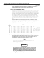
Restarts for autonumbers that do not restart in each
chapter.
figure bi level 1, reset
table_big level 1, reset
chap_big level 1, reset
app_big level 1, reset
figure_ap level 1, reset
table_ap level 1, reset
figure level 1, reset
table level 1, reset
these restarts must be in the header frame of chapter 1.
a:ebx, l 1 resetA
a:obx:l 1, resetA
a:bigbx level 1 resetA
a:ftr level 1 resetA
c:ebx, l 1 reset1
c:obx:l 1, reset1
c:bigbx level 1 reset1
c:ftr level 1 reset1
Reminders for autonumbers that need to be restarted
manually (first instance will always be 4)
let_in level 1: A. B. C.
letter level 1:A.B.C.
num level 1: 1. 2. 3.
num_in level 1: 1. 2. 3.
rom_in level 1: I. II. III.
roman level 1: I. II. III.
steps level 1: 1. 2. 3.
October 1999
GFK-1434C
IMPORTANT PRODUCT INFORMATION
READ THIS INFORMATION FIRST
Product:
PLC CPU Module CPX928, Release 8.00
IC697CPX928-BC
Purpose
This document applies to CPU module IC697CPX928. It discusses three topics: (1)
general information about this module, (2) features of current firmware release 8.00, and
(3) features of previous firmware release 7.92. Since some of this information is not
available in any other publication, it is suggested you save this document for future
reference.
Identification
Hardware identification is summarized in the following table.
Hardware Identification
Catalog Number
IC697CPX928
Board
Identification
Board Revision
CPXA1
44A739520-G01 R04 or later (motherboard)
HPMA1
44A736472-G01 R03 or later (memory board)
Packaging Note
A user manual is not shipped with every product. User manuals are provided as a
complete set in a library with MS-DOS and Windows Programming Software
products, are available on CD-ROM, or are available as individual manuals. To order any
of this documentation, use the information in the following heading.
R
R
Firmware Upgrade Kit
Users wishing to upgrade previous versions of this CPU to version 8.00 may order
Upgrade Kit 44A747755-G02.
Documentation
The following documentation products are available for the IC697CPX928:
PLC Reference Manual
PLC Installation Manual
PLC Systems Manual
Data Sheet, GFK-1433
Full documentation sets are also available in either printed/bound form or in electronic
form (CD-ROM). These are listed in the following table.
R
MS-DOS and Windows are registered trademarks of Microsoft, Inc.
Important Product Information: PLC CPU Module CPX928, Release 8.00
2
GFK-1434C
October 1999
Full Documentation Set
Catalog Number
Description
IC697LBR701*
Paper library - full set of printed manuals
IC690CDR002*
CD-ROM - full set of manuals in electronic format
* Current version will be shipped.
Special Operation Notes
MS-DOS Programming Software Compatibility
This release of the CPX928 CPU module is compatible with the versions of MS-DOS
programming software listed in the table below. This software supports
configuration of the module’s Serial ports, Port 1 and Port 2, and User Flash Memory.
However, the MS-DOS programing software does NOT support most of the features
new to Release 7 or later CPUs, such as Ethernet Global Data, I/O Scan Sets, VME
3rd Party Interrupts, and Bulk Memory Access (BMA).
Beginning with revision IC697CPX928BA, an upgrade copy of the MS-DOS
Programming software is packed with the CPU module.
MS-DOS Programming Software Compatibility
CPU Model
Software Version
IC697CPX928
IC697 Version 7.02 or later
Windows Programming Software Compatibility
This release of the CPX928 CPU module is compatible with the versions of the
Windows based programming software listed below. This software supports
configuration of the module’s Serial ports, Port 1 and Port 2 , and User Flash
Memory, as well as the features new to Release 7 or later CPUs, such as VME 3rd
Party Interrupts, and Bulk Memory Access (BMA).
Windows Programming Software Compatibility
CPU Model
Software Version
IC697CPX928
Version 2.2 or later
Beginning with revision IC697CPX928BA, an upgrade copy of the Windows
Programming software is packed with the CPU module.
PCM and BTM Compatibility
With the introduction of timing improvements and new features first made available in
Release 5.00, it is highly recommended that systems using PCMs (Programmable
Coprocessor Modules) use IC697PCM711J or later. It is also highly recommended that
3
Important Product Information: PLC CPU Module CPX928, Release 8.00
GFK-1434C
October 1999
systems using BTMs (Bus Transmitter Modules) use IC697BEM713B or later. Use of
boards of an earlier revision may result in lower system performance.
PCM (to CPU) Communications Timeout
The PCM has a default backplane communications timeout value of 5 seconds. After
the PCM has sent a request to the IC697 CPU, the PCM applies this timeout while
waiting on a response back from the CPU. In most cases, the CPU will respond well
within the 5–second timeout; however, in certain instances the CPU can take longer
than 5 seconds to respond. These cases are limited to LOADs or STOREs of program
and/or configuration - especially if blocks in the program are larger than 8 KBytes. Folders
containing EXE blocks (again with *.EXE files >8 KBytes) are most likely to cause problems.
Beginning in Release 6.00, Standalone C programs larger than 8 Kbytes also cause this to
happen.
Beginning in Release 5.50 of the IC697 CPUs, the CPU is guaranteed to respond
within 8 seconds. To ensure that the PCMs do not observe backplane timeouts, a file
must be loaded (using termf) to the PCM. The file must be a binary file named
CPU.ENV. The contents of this file are as follows (all values are specified in
hexadecimal):
FILE
OFFSET
DATA
0000
4C
5A
01
01
00
00
00
00-00
00
00
00
01
00
00
00
LZ . . . . . . . . . . . . . .
0010
00
00
00
00
00
00
00
00-00
00
43
50
55
4C
49
4E
. . . . . . . . . .CPULIN
0020
4B
2E
43
4F
44
00
2D
62-00
36
34
00
2D
74
00
32
K . C O D . –b . 6 4 .–t . 2
0030
30
30
00
00
43
50
55
4C-49
4E
4B
2E
44
43
42
00
0 0 . .C P U L I NK . D C B .
0040
00
4E
55
4C
4C
3A
00
4E-55
4C
4C
3A
00
4E
55
4C
. N U L L: . N U L L : . N U L
0050
4C
3A
00
00
00
00
00
00-00
00
00
00
00
00
00
00
L : . . . . . . . . . . . . . .
0060
00
00
00
00
00
00
00
00-00
00
00
00
00
00
00
00
. . . . . . . . . . . . . . . .
0070
00
00
00
00
00
00
00
00-00
00
00
00
00
00
00
00
. . . . . . . . . . . . . . . .
Once the binary file CPU.ENV (above) is created, use termf to load CPU.ENV to the
PCM. Then execute a soft reset of the PCM. After executing the soft reset, the
PCM’s backplane communications timeout should be 10 seconds.
Note
A copy of the above CPU.ENV file can be obtained from your PLC
technical support Internet site.
CAUTION
The CPU.ENV file will not be used when a hard reset is performed on the
PCM. With the CPU.ENV file resident in the PCM, a soft reset must be performed after every hard reset of the PCM. Be aware that it is possible to issue a soft reset COMMREQ from the Ladder Diagram application; therefore, the application can be modified to handle the required reset of PCMs
after a power cycle of the PLC system.
Important Product Information: PLC CPU Module CPX928, Release 8.00
4
GFK-1434C
October 1999
Notice to Upgrade GBC Hardware
With the introduction of new features in CPU Release 5.00, timings with the IC66*
Bus Controllers (GBCs/NBCs) changed; this uncovered a problem in the GBC/NBC
firmware. GBCs/NBCs in expanded racks could be lost if the system is fully
configured and only the main rack cycles power.
Also, in previous versions of the GBC/NBC there was a problem with input data
coherency. In a system with a long CPU sweep time and a short IC66* bus scan
time, a problem could be seen if a device is lost. Input data could be defaulted off
while the CPU is reading the data from the GBC/NBC.
It is recommended to update existing GBC/NBC hardware to IC697BEM731M or
later when updating PLC CPU firmware to Release 7.92. Operation of the
IC697BEM731M, in conjunction with Release 7.92 of the IC697 CPU will result in a
slight impact to the I/O scan time of the PLC.
Third Party VME Modules
MS-DOS programming software Release 5.00 (and later) allows 3rd Party VME
modules to be configured for six modes: NONE, INTERRUPT ONLY, BUS
INTERFACE, FULL MAIL, I/O SCAN, and REDUCED MAIL. However, CPU Release
7.92 does not support REDUCED MAIL.
Maximum PLC Sweep
In systems configured for IC66* Bus Redundancy, a complete PLC sweep must be
executed every 500 milliseconds or less, even though it is possible to configure the
watchdog timer to higher limits. This also means that resetting of the watchdog
timer with Service Request #8 cannot be done indefinitely.
Serial Communications
The following operating restrictions exist for the Serial Communications feature:
1.
Serial communications can add up to 5 milliseconds of time to any given sweep.
This should be taken into account when setting the watchdog timer.
2.
The following procedure is recommended if you are using a WSI board and wish
to change baud rates for the PLC and the WSI board. First, use the configuration
software to change the baud rate on the PLC, then store the new configuration.
Next, power off the PLC, then go to the WSI setup screen and change the WSI
baud rate. Finally, power the PLC back on.
3.
The link idle time setting in the MS-DOS programming software Config for Serial
Communications should be set to 10 seconds or greater. Otherwise, a communications failure will occur when storing the config to the PLC.
Serial Port Mode Configuration (Applies to Port 3 Only)
The Serial Port 3 configuration parameter called MODE can be one of two values: (1)
SNP to indicate that the port will be used for SNP communications, or (2) MSG to
indicate that the serial port will be used to send printf commands from a C program
block to the connected device. If you configure MODE to be MSG and are also
Important Product Information: PLC CPU Module CPX928, Release 8.00
GFK-1434C
5
October 1999
using Port 3 to connect to your PLC programmer, communications with the PLC
programming software will be lost when going to the RUN mode, since the
programming software requires the SNP protocol. In this case, we recommend you
use either Serial Port 1 or 2 for communicating with the programming software,
since these support only SNP; however, be aware that this capability for Ports 1 and
2 was first made available in Firmware Release 8.00.
MS-DOS/WSI Attach
Do not connect or disconnect the WSI/BTM cable while the programmer host is
powered-on. This action may cause a running PLC to Stop.
Expansion Rack ID
The expansion racks for the IC697 PLC are shipped with the rack ID strapped for
rack 0 (the main rack). If the rack jumper is not changed, the PLC will not recognize
the rack at all and may not properly identify the error.
Expansion Rack Cable
Do not connect or disconnect the expansion rack cable while the CPU is running.
This will cause the PLC to go to the STOP/HALT mode.
Expansion Rack Power
Expansion racks should be powered up at the same time that the main rack is
powered up, or they should be powered up after the main rack has completed its
power-up initialization. Do not power-up an expansion rack while the CPU is running
power-up diagnostics.
Memor y Usage
A general rule-of-thumb for memory usage is 48 bytes per I/O point plus register
memory in bytes.
Timer Operation
Care should be taken when timers (ONDTR, TMR, and OFDTR) are used in
program blocks that are NOT called every sweep. The timers accumulate time
across calls to the sub-block unless they are reset. This means that they function like
timers operating in a program with a much slower sweep than the timers in the
main program block. For program blocks that are inactive for large periods of time,
the timers should be programmed in such a manner as to account for this catch up
feature.
Similar to this are timers that are skipped because of the use of the JUMP instruction.
Timers that are skipped will NOT catch up and will therefore not accumulate time in
the same manner as if they were executed every sweep.
I/O Link Interface
When powering up the PLC CPU without a battery, and I/O Link Interface boards
are present, an incorrect Loss of Module fault will be logged for each I/O Link
6
Important Product Information: PLC CPU Module CPX928, Release 8.00
GFK-1434C
October 1999
Interface board. The PLC CPU will not consider these boards as lost, and the boards
will continue to operate properly.
CommReqs with Retentive Memory
When powering up the PLC CPU with a program being retrieved from Retentive
Memory and proceeding to RUN mode, any CommReqs to a PCM should be
delayed for 5 seconds.
Constant Sweep
Constant Sweep time, when used, should be set to about 10 milliseconds greater
than the normal sweep time to avoid any oversweep conditions when monitoring or
performing on-line changes with the programmer. The smallest valid constant
sweep time setting is 10 milliseconds for the Model CPX928 PLC. Window
completion faults will occur if the constant sweep setting is not high enough.
Interaction of MS-DOS Programming Software with Closed Programming Window
The MS-DOS programming software PLC Sweep Control and Monitor screen
cannot be used to change the PLC Sweep Modes or timers (Constant Sweep Time,
Program Window Times, etc.) while the program window is closed. Use Service
Requests #1 through #4 to perform these functions.
Caution
TheMS-DOS/Windows programming software cannot be used to
change the PLC mode (STOP/RUN, etc.) while the programming
window is closed. Use the toggle switch on the CPU module instead.
Model CPX928 CPU Ambient Temperature
Due to the high power dissipation of the Model CPX928 CPU microprocessor,
ambient temperature during operation must be kept at or below 50 degrees Celsius.
With forced air cooling (70 CFM), up to 60 degrees Celsius is allowed.
Fan assemblies IC697ACC721 (120 VAC) and IC697ACC724 (240 VAC) are available
for direct mounting to the IC697 rack.
Please see the data sheets for this product (IC697CPX928) and for the fan assemblies
listed above (IC697ACC721 and IC697ACC724) for more information.
SFC RESET Function Block
The SFC RESET function block only executes when used in Action Logic or Pre/Post
Logic within an SFC block (Main SFC or SFC sub-block). Attempting to execute an
SFC RESET function block from a Ladder Diagram Main/sub-block will not reset the
SFC network, and (as of version 6.02) will not pass power flow to any logic right of
the SFC RESET.
Ethernet Global Data and Sweep Time
Each Ethernet Global Data exchange configured for either consumption or
production can add up to 1 msec to the sweep time. This sweep impact should be
Important Product Information: PLC CPU Module CPX928, Release 8.00
GFK-1434C
7
October 1999
taken into account when configuring the PLC constant sweep mode and setting the
CPU watchdog timeout.
Serial Ports 1 and 2
This CPU is equipped with two additional serial ports (Ports 1 and 2) as well as the
standard serial port (Port 3) found on previous IC697 CPU models. Port 1 supports
the RS-232 standard, and Port 2 supports the RS-422/485 standard. These additional
serial ports support the following baud rates: 1200, 2400, 9600, 19200, 38400, and
57600. Note that they do not yet support 115K baud. Both ports can be operated
simultaneously without dropping characters up to 57600 baud.
SNP Slave protocol support for these ports was added in Firmware Release 7.80.
Break-Free SNP (Slave) was added as the default protocol to Ports 1 and 2 in
Firmware Release 8.00 (Serial Port 3 does not support Break-Free SNP). All
functionality of Serial Port 3 is available through Ports 1 and 2 with these exceptions:
(1) they do not support connection of the C debugger, (2) they do not support printf
functionality using C programming, (3) Datagram memory sizes may be different.
See the item “Datagram Memory Sizes” in this section.
All three serial ports can be configured by both MS-DOS and Windows
programming packages for selecting baud rate, parity, stop bits, etc.
If upgrading this module from a previous version that did not support these two
ports, you may have to set up the ports’ configuration parameters (using a
programmer connected to Port 3) before you will be able to use the ports.
Programmer Communications Issues (Serial Ports 1 and 2)
When using Serial Ports 1 or 2 for programmer communications, a momentary loss
of communications may be observed after a store of hardware configuration while
configuration settings are being updated. This is normal operation.
Note that all port communications settings should be carefully verified before
performing a hardware configuration store. If any of the essential configuration
settings (such as mode, baud rate, parity, etc.) for the port connected to the
programmer are changed, you will lose communications after a configuration store.
Communications will be restored once the host (programmer) settings are changed
to match the port’s new settings.
User Flash Memory
The CPX928 board supports a user flash memory option which allows you to store
program logic, configuration data, reference tables, passwords, and the OEM key to
the flash memory device located on the CPX928. This feature supports the current
flash memory operation available on the IC697CPU782 with 256K flash memory
daughterboard.
CMM and PCM Module Compatibility
Due to the increased reference table sizes on the CPX CPU models, older versions of
CMM and PCM modules may experience compatibility problems with the CPX
model CPUs. Firmware upgrades are available for customers with other versions of
these modules.
Important Product Information: PLC CPU Module CPX928, Release 8.00
8
GFK-1434C
October 1999
CMM modules (IC697CMM711) of revision ’F’ or later will not experience this
problem.
PCM modules (IC697PCM711) of revision ’F’ or later will not experience this
problem.
Datagram Memory Sizes
The number and sizes of datagrams established using Serial Ports 1 and 2 may be
different that those of Serial Port 3. This is because the memory spaces allocated for
datagrams for Ports 1 and 2 are fixed sizes, but Serial Port 3 shares its datagram
memory space with hardware configuration data. Therefore, the Port 3 datatgram
memory allocation may be larger or smaller than Ports 1 and 2 depending on the
amount of configuration data required by the system.
Problems Resolved by this Firmware Release (8.00)
None to report.
Problems Resolved by Previous Firmware Release (7.92)
1.
The CPU would fail if Loss of Module or System Configuration Mismatch faults
were logged against an Ethernet module. This failure only occurred if point faults
were enabled in the CPU and the status word for the Ethernet Module was
configured for %R memory.
2.
Large FBC Configuration Files (more than 4K bytes) were not being transferred
completely on powerup.
3.
User Flash Operations for the CPX CPU boards could not be used when an Ethernet
Adapter board was in the system. Doing so would result in failure of the PLC CPU.
4.
The masked compare function block did not operate correctly when the first input
parameter (first bit string) was not aligned on a word boundary (for example,
%M0009 instead of %M0017). Using the masked compare function block in this way
would access a byte in memory just before the MASK parameter resulting in an
incorrect mask being applied on an invalid memory access.
5.
When Run Mode Store is used to delete programs and more than 8 programs exist in
the PLC, the subsequent Run Mode Store operations that add programs can
sometimes result in one of the programs being deleted.
6.
The total program logic size returned by the PLC to the Programmer, when at least
one C Program Block is defined, is incorrect.
7.
The size of Standalone C programs reported in the Program Memory screen of the
IC697 MS-DOS Programming Software is too large by about 500 bytes. Therefore,
this screen may indicate that a Standalone C program slightly larger than the
program limit has been stored to the PLC CPU.
8.
Application changes with more than 200 program blocks in CPU: The CPU now
correctly returns the list of stored program blocks when more than 200 program
Important Product Information: PLC CPU Module CPX928, Release 8.00
GFK-1434C
9
October 1999
blocks (including _MAIN) are used. Previously, an invalid list was returned which
could cause attempts to Run Mode Store via Ethernet to fail resulting in the MS-DOS
Programming Software to continuously report ”BUSY.” Likewise, a store of
hardware configuration without also storing the Logic Program sometimes failed if
the CPU already contained more than 200 program blocks. In both of these cases,
the original Logic Program and Hardware Configuration remained intact in the CPU
and control was unaffected.
Programs having fewer than 200 program blocks did not manifest this problem.
Also, releases prior to Release 7.00 did not have this problem.
As of the date of this CPU release, the Host Communications Toolkit (HCT) still has a
problem with more than 200 program blocks. HMI and other software packages that
use the HCT to obtain the list of program block names from the CPU may
experience communication failures when the application has more than 200
program blocks.
New Features and Functionality of this Firmware Release (8.00)
Enhanced Functionality of Serial Ports 1 and 2
D
Serial Ports 1 and 2 now support “break-free” SNP. Break-free SNP improves serial
communication using modems. The break-free implementation of the SNP protocol
does not rely on receiving serial breaks. Consequently, modem pairs that alter the
timing or characteristics of breaks from SNP masters may be used successfully. Note
that break-free is now the default mode of operation for the SNP protocol on these
two ports. Break-free operation is completely transparent. When normal breaks are
received, SNP communication is identical to previous releases. However, Attach
messages are also recognized without a preceding break. Modified breaks (for
example, breaks transformed to a single ASCII NUL character with or without a
framing error) are ignored.
D
Serial Ports 1 and 2 now fully support programming using either the DOS or the
Windows programming software, including the program upload, download, and
data monitoring features. See the note below for programming limitations.
Note
Serial Ports 1 and 2 do not support connection of the C debugger or
printf functionality using C programming.
New Features and Functionality of Previous Firmware Release (7.92)
1.
Clock Synchronization using FIP and/or SIO Module. The Clock Synchronization
feature allows the user to synchronize the CPU’s Time-of-Day clock to a master clock
external to the CPU. Two types of synchronization are supported: a) External Clock
Synchronization which synchronizes based on a timestamp from the FIP network
that identifies the point at which a signal is sent to the SIO module, and b) Network
Clock Synchronization where the time is synchronized using the FIP network.
2.
Multi-threaded LD Program Capability (MTLD). The MTLD feature allows you to
have, in effect, multiple LD programs by giving C programs the ability to call LD
blocks in the LD program.
Important Product Information: PLC CPU Module CPX928, Release 8.00
10
GFK-1434C
October 1999
3.
Run Mode Store in Microcycle Sweep Mode. Run Mode Store is now permitted
when in microcycle mode. Programs are swapped at a point where no programs are
executing in the system.
4.
Read/Write of PLC CPU Memory using Service Request Function Block. Selected
memory types can be read or written using a new service request function block.
The list of memory types is limited to Bulk Memory, FIP Specific Information, and
the BCP direct cache.
5.
Bulk Memory Access (BMA). BMA provides a large block of memory that can be
accessed from your application program. Possible uses include recipe files, bulk
storage, memory allocation, temporary memory blocks, etc. Use of this feature
requires the Windows Programming software version 2.2 or later. (The DOS
programming software does not support it.) Enhancements to the on-line help for
this feature were added to this software in version 2.3.
6.
C Toolkit Enhancements. Version 5 of the C Toolkit supports access to BMA (feature
5 above) and supports MTLD (feature 2 above).
Restrictions and Open Problems
1.
If an expansion rack powers up while the CPU in the main rack is in the RUN mode,
the slot fault contacts will prematurely indicate that the modules in the expansion
rack are not faulted before they complete their power up.
2.
When there is no logic stored in a CPU module, the %Q and %M tables will be
cleared when the CPU is placed in RUN mode. In this context, no logic stored means
that no program had ever been stored or that the clear function on the MS-DOS programming software had been used to clear logic and configuration.
3.
When the Bit Sequencer sequences from one step to another, the negative transitional contact that corresponds to the original step is not set. The transition contact for
the new step is set and remains set until the sequencer sequences to the next step.
This operation is identical to the operation of the previous versions of the CPU firmware.
4.
If multiple faults exist in an IC697 PLC remote drop and one of them is corrected, a
FAULT contact that uses the remote drop’s module reference will incorrectly indicate
that no faults exist at the remote drop.
5.
An incorrectly formatted COMMREQ (for example, incorrect task id field) directed
to a PCM or CMM module does not result in an error being logged in the PLC fault
table. Correctly formatted COMMREQs operate normally.
6.
The bit sequencer function block clears bits outside the range of the function’s length
parameter when the reset condition is TRUE. The affected bits lie within the bytes
accessed by the function. For example, with length 100 (bits), the four bits at 101,
102, 103, and 104 are cleared by the bitseq function when it is reset. This operation is
identical to the operation of the previous versions of the CPU firmware.
7.
A large number of COMMREQs (typically greater than 8) sent to a given board in
the same sweep may cause a Module Software fault to be logged in the PLC fault
table. The fault group is MOD_OTHR_SOFTWR (16t, 10h) and the error code is
COMMREQ_MB_FULL_START (2). When this occurs, the FT output of the function
block will also be set. To prevent this situation, COMMREQs issued to a given board
Important Product Information: PLC CPU Module CPX928, Release 8.00
GFK-1434C
11
October 1999
should be spread across multiple sweeps so that only a limited number (typically 8
or less) of COMMREQs are sent to a given board in each sweep. In addition, the FT
output parameter should be checked for errors. If the FT output is set (meaning that
an error has been detected), the COMMREQ should be re-issued by the application
logic.
8.
When attempting simultaneous loads of logic through multiple ethernet connections
and a serial connection, the loads through the ethernet connection may fail with a
communication timeout.
9.
On occasion, the PLC may fail to respond to an SNP Attach message issued through
Serial Ports 1 or 2. Several retries of the SNP Attach message may be necessary to
successfully attach to the PLC via these two ports. Therefore, users developing their
own SNP applications to run on these two ports should design and code for multiple
SNP Attach retries.
10. PSB Y0 is not saved and restored across calls to nested PSBs (Parameterized
Subroutine Blocks). A single location in bit cache memory is used for storing the Y0
value, and this bit is set to “1” upon each invocation of a PSB block. Use a different
variable to store the value of Y0 across the call and set Y0 immediately prior to
exiting the block. Care should be taken when using Y0 both within a PSB block
called by an interrupt block and in the block called by the main LD program.
Additions to the PLC Reference Manual
Wait Mode Comm_REQs
Wait mode COMM_REQs cannot be directed to the new serial ports (ports 1 and 2). This
should be added to page 4-91 of the H version of the Programmable Logic Controller
Reference Manual.
MOV_BIT Instruction
The documentation for the MOV_BIT instruction indicates that transition references are
modified only for the bits in the range of the function block (page 4-76 of the H version
of the Programmable Logic Controller Reference Manual). The manual should state that the
transition references of all bytes in the range are modified.
Parameterized Subroutines (PSB and SUBR)
PSB output parameters of type BIT will affect the transitions in all bytes within the range
of the BIT parameter. For example, a BIT parameter of length 4, connected to physical
output %Q6, will affect the transitions of all bits within the byte containing %Q1
through %Q8 as well as all bits in the byte containing %Q9 through %Q16.
For arrays of BIT type, each array element is written one bit after the other. Since
memory write operations and management of transitional state are done a byte at a
time, the transitional status of each element will typically be cleared, except for the final
array element. This is not an issue for BIT parameters of length 1, as only a single write
operation is performed. Note, however, that as described above, the transition value of
other bits within the byte will be affected.