1
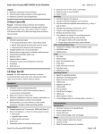
Back Panel
Ethernet
Port
Expansion
Port
Powerpole Nodes
“Nodes” 1 - 5
DC IN
Powerpole Connection
Front Panel Description
LCD – status screen operating in two modes: Scrolling status mode or Individual status mode.
Next/Exit Buttons – operation for LCD display
Node LEDs – The LED above the button indicates the current state of that node
• Unlit – Power-pole node is not active and no power is being supplied to the node.
• Green – Power-pole node is active and power is being supplied to the node.
• Red – The soft fuse has blown and no power is being applied to the node.
Node Enable Buttons – button press will toggle the ON/OFF state of each node or Reset Fuse.
LCD Display
Next / Exit
Buttons
Node LED
Status Indicators
Node Enable
Buttons
Node Enable and Soft Fuses
Each Powerpole node has a toggle button to enable/disable node. Pressing the corresponding button will
toggle the ON/OFF state of the Powerpole node. The LED above the button indicates the current state of that
power-pole.
The ON/OFF state is stored in program memory and retained if power is lost to the RIGrunner.
Each node has a “soft fuse”, meaning that it is a user configurable setting. The fuse value can be configured
from the web browser over a network connection. If the soft fuse has been blown, the Node Enable Button
must be pressed twice to return to ON status. NOTE: The first button press disables the node and the second
button press enables the node.
West Mountain Radio
3
Operating Manual