1
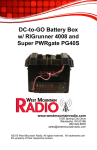
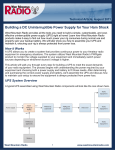
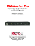
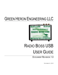
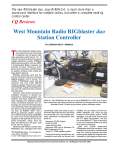
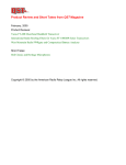
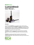
www.westmountainradio.com
1020 Spring City Drive
Waukesha, WI 53186
262-522-6503
[email protected]
©2012 West Mountain Radio, All rights reserved. All trademarks are
the property of their respective owners.
Thank you for choosing the PWRguard PLUS from West Mountain
Radio. This product is designed to protect your 12VDC equipment
and battery against system power faults. An optional external sense
input is available on PWRguard PLUS for further protection of your
equipment.
The method of operation is to disconnect the load if the supply
voltage is outside the normal range (11.0V to 15.0V) or the external
sense input is activated. The sense input can be triggered from an
external dry contact closure or a low voltage input (3.0 to 5.0VDC).
One example would be connecting a sensor that detects water in a
basement, and PWRguard PLUS would shut down power. Another
useful example is to have a sense input connected to a key switch to
enable power from PWRguard PLUS.
The PWRguard PLUS also has a piezo buzzer alarm which will sound
once per minute during load disconnect. This alarm can be disabled if
you do not need an audible alert.
Modes of Operation: Automatic and Manual
Automatic Mode
Supply Voltage Not In Normal Range: When the supply voltage is
outside of the normal range the PWRguard PLUS will disconnect
the load. Upon restoration of normal supply voltage the load will be
reconnected automatically.
Sense Input Triggered: When the sense input is activated the
PWRguard PLUS will disconnect the load. When the sense
condition is cleared the PWRguard PLUS will automatically
reconnect the load unless supply voltage is outside of normal
levels.
Manual Mode
Supply Voltage Not In Normal Range: When the supply voltage is
outside of the normal range the PWRguard PLUS will disconnect
the load (as above) and permit a manual reset only when the
power is within the normal voltage range.
Sense Input Triggered: When the sense input is activated the
PWRguard PLUS will disconnect the load. When the sense
condition is cleared the PWRguard PLUS will automatically
reconnect the load unless supply voltage is outside of normal
levels.
West Mountain Radio
2
Operating Manual
Installation
1. Install the PWRguard PLUS between the power source and the
loads to be protected.
NOTE: The unit comes fitted with Powerpole connectors for ease of
installation into your power system.
Input (power source) connects on the left side of the case.
Output (load) connects on the right side of the case.
Make sure that you only connect the RED lead to POSITIVE, and the
BLACK lead to NEGATIVE.
2. Install the unit in a cool dry location. The case may be fastened
down using the mounting holes on the flanges.
3. The external sense terminal is located within the unit. Remove the
case and locate the small terminal-block on the left hand side. The
terminal nearest the edge of the board provides +5VDC through a
330 ohm resistor and the right terminal is the sense input.
The piezo buzzer alarm can be disabled by removing the jumper
from the terminal post marked “Buzzer”.
4. When the power supply is switched on, the PWRguard Plus unit will
become operational and the AUTO RESET and ON LEDs will both glow green. If the AUTO RESET LED does not turn on, hold
the reset button down for 5 seconds until it does. If the YELLOW
LED (Low fault) comes on instead of the ON LED, it means that your
power supply or battery voltage is too low. PWRguard Plus requires
at least 13.5 volts to become operational when turned on.
This setup integrates PWRguard Plus into a UPS. The PWRGuard
Plus input is connected to the output of the Super PWRgate. The
PWRguard Plus output is connected to the input of the RIGrunner.
This setup will protect the battery from deep discharge after an AC
power loss, and all devices that are plugged into the RIGrunner from
under and over voltage. After AC power is restored, the battery will
be recharged through the Super PWRgate and PWRguard Plus will
reset the system.
5V DC
Buzzer Jumper
Sense Input
West Mountain Radio
3
Operating Manual
Minimal Set Up
Integrated Set Up
This set-up connects PWRguard PLUS input to the Super PWRgate
PG40S output terminal and then plug the PWRguard PLUS output into
the RIGrunner input terminal. This will provide protection for the battery
and all the devices that are plugged into the RIGrunner. Additionally,
after loss of AC mains power, the PWRguard PLUS will reset the system
after the power is restored.
West Mountain Radio
4
Operating Manual
Fuse
The PWRguard PLUS fuse is used to protect the source and the load
from excessive current. The PWRguard PLUS includes a 40A fuse (the
rating of the PWRguard PLUS.) The fuse may be changed to a lower
value if desired for protection of other system components downstream.
Operating In Automatic Reset Mode
The PWRguard PLUS unit is operational whenever it is connected to
the 12V power source. There is no ON/OFF switch needed. This is the
Factory Default Mode Setting.
GREEN LED –
Output ON
When the source voltage is between 11.0 and
15.0V (nominally 13.8V), the large green LED will
light showing that the output is ON. The small LED
indicates the PWRguard PLUS is in Automatic Reset
Mode.
RED LED –
Hi-Fault
The RED LED (Hi-Fault) will light whenever the
input voltage exceeds 15V. The GREEN LED will
go OFF and there will be NO output voltage. In
the automatic reset mode, the RED LED will turn
off when the input voltage returns to less than 15V,
and the output will turn ON, thereby relighting the
GREEN LED and re-powering the load.
The YELLOW LED (low-fault) will light whenever the
input voltage drops below 11.0V. This LED will also
briefly light if there are momentary dips below 11.0V.
This feature assures correct operation during turn-on
surge currents and during SSB or CW transmission
when powered from a battery supply. The voltage
YELLOW LED– may drop each time the power requirement peaks.
Low-Fault
If the voltage continues to be below 11.0V for more
than 5 seconds, the LED will light continuously. This
state will continue until the voltage is continuously
below 11.0V and indicates the battery is nearing its
drained state. The GREEN LED will go OFF, thereby
turning the output OFF. The PWRguard PLUS will
now remain OFF. When the input voltage returns to
13.0V, the PWRguard PLUS will automatically reset.
Operating In Manual Reset Mode
To configure this mode, hold the reset button down for 5 seconds and
the small green “AUTO RESET” LED will go OFF.
West Mountain Radio
5
Operating Manual
Cold Start
GREEN LED –
Output ON
The PWRguard PLUS will automatically reset from a
cold start condition.
When the source voltage is between 11.0 and 15.0
Volts (nominally 13.8 volts), the large green LED will
light showing that the output is ON. The small LED,
being off, indicates the PWRguard PLUS is in Manual
Reset Mode.
The RED LED (Hi-Fault) will light whenever the input
voltage exceeds 15.0V. The GREEN LED will go OFF
and there will be NO output voltage. In the
RED LED –
Hi-Fault
Manual Reset Mode when the input voltage returns
to less than 15.0V, the RED LED will flash indicating
a return to safe voltage condition. The PWRguard
PLUS can then be manually Reset, thereby
repowering the load and lighting the GREEN
LED.
The YELLOW LED (low-fault) will light whenever the
input voltage drops below 11.0V. This LED will also
light briefly if there are momentary dips below
11.0V. This feature assures correct operation during
turn-on surge currents and during SSB or CW
transmission when powered from a battery supply.
YELLOW LED
– Low-Fault
Manual to
Auto Reset
The voltage may drop each time the power
requirement peaks. If the voltage continues to be
below 11.0V for more than 5 seconds, the Yellow
LED will light continuously. This state will continue
if the voltage is continuously below 11.0V and the
battery is nearing its drained state. The GREEN LED
will go OFF thereby turning the output OFF. The
PWRguard PLUS will remain OFF. When the input
voltage returns to 13.0V, the YELLOW LED will begin
to flash indicating the supply voltage has recovered.
The PWRguard PLUS can then be Manually Reset,
thereby, relighting the GREEN LED and re-powering
the load.
To restore auto mode, hold the reset button down
again for 5 seconds. The small green LED will light.
West Mountain Radio
6
Operating Manual
Additional Modes
Automatic Battery Save Mode
The PWRguard PLUS is designed to protect a battery from any additional
current drain following a long turn off period of 60 minutes. This “Sleep Mode”
will further reduce battery power drain by limiting the on time of the Yellow
LED. Normal operation will be restored when the input voltage returns to the
safe operating range, and the unit is manually or automatically reset. When
the unit is in Sleep Mode there is very limited power drain.
Voltage Sensing Circuits
Units are factory calibrated for the specified trip points and delays.
Contact West Mountain Radio to have units programmed for special
applications.
LED Indicators
Green
Red
ON – Load powered
OFF – Load off
ON – Voltage too high
Blink – Voltage good – waiting for reset
ON – Voltage too low
Yellow
Blink – Voltage good – waiting for reset
Short Interval Blink – Battery Save Mode
Specifications
Electronics
Maximum voltage: 35 VDC
Current:
< 30 mA Normal Mode
< 5mA Sleep Mode
Solid State
Switch
Continuous Current: 30 A
Maximum Current:
40 A
Nominal ON resistance: 5 milliohms
Switching
Ranges
Hi Trip:
Low Trip:
Auto Re-Start:
15.0 ± 0.1VDC
11.0 ± 0.1VDC
13.0 ± 0.1VDC
Hi-Trip:
Low-Trip:
Mode Select:
Sleep Mode:
10 milli-seconds
3.3 Seconds
5.0 Seconds
60 Min
Switching TimeConstants
West Mountain Radio
7
Operating Manual
Warranty
PWRguard Plus is warranted against failure due to defects in workmanship or
materials for one year after the date of purchase from West Mountain Radio.
Warranty does not cover damage caused by abuse, accident, misuse, improper
or abnormal usage, failure to follow instructions, improper installation, alternation, lightning, or other incidence of excessive voltage or current. If failure
occurs within this period, return the PWRguard Plus or accessory to West
Mountain Radio at your shipping expense. Repaired or replaced items are warranted for the remainder of the original warranty period. You will be charged for
repair of replacement of the Pwrguard+ or accessory made after the expiration
of the warranty period.
West Mountain Radio shall have no liability to customer or any other person or
entity with respect to any liability, loss or damage caused directly or indirectly
by use of performance of the products or arising out of any breach of this warranty, including, by not limited to, any damages resulting from inconvenience,
loss of time, data, property revenue, or profit, or any direct, special incidental,
or consequential damages, even if West Mountain Radio has been advised of
such damages.
Except as provided herein, West Mountain made no express warranties and
any implied warranties, including fitness for a particular purpose, are limited in
duration to the state duration provided herein.
FCC INFORMATION
For a Class B digital device or peripheral, the user instructions shall include the
followling or similar statement, placed in a prominent location in the text of the
manual:
Note: This equipment has been tested and found to comply with the limits for
a class B digital device, pursuant to part 15 of the FCC Rules. These limits
are designed to provide reasonable protection again harmful interference in a
residential installation. This equipment generates,uses and can radiate radio
frequency energy, and if not installed and used in accordance with the guarantee that interference will not occur in a particular installation. If this equipment
does cause harmful interference to radio or television reception, which can be
determined by turning the equipment off and on, the user is encouraged to try to
correct the interference by one or more of the following measures:
•Reorient or relocate the receiving antenna
•Increase the separation between the equipment and receiver
•Connect the equipment into an outlet on a circuit different from that to which the receiver is connected.
•Consult the dealer or an experienced radio/TV technician for help.
Modifications not expressly approved by the manufacturer could void the user’s
authority to operated equipment under the FCC Rules.
West Mountain Radio
8
Operating Manual