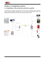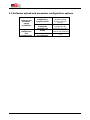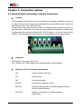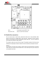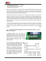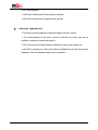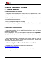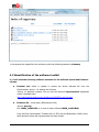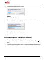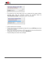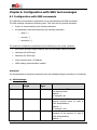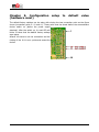
1
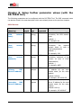
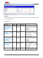
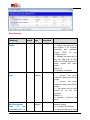
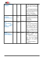
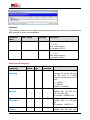
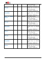
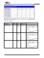
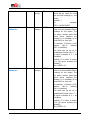
M2M Easy Communicator ® Installation Guide _____________________________________ Rev: 1.1.6 2012-05-07 Document specification This document was made by the WM Rendszerház Kft. for the M2M Easy Communicator® device. This Technical Specification contains the description of the installation and configuration steps. Document category: Installation Guide Product: M2M Easy Communicator Made by: Tóth Csaba, WM Rendszerház Kft. Contact: Email: [email protected] Validated by: Papp Zsolt Document version: REV 1.1.6 Pages: 71 Hardware version: REV 2.1 Bootloader version: REV 0v89 Firmware version: Document status: REV 1v592 Class: Public Made at: 22nd of March, 2012. Last changes: 7th of May 2012. Date of authorization: 7th of May 2012. Final 2 Table of Contents 1. CONFIGURATION OPTIONS .......................................................................... 2 1.1 Possibilities of the utilization and data connection .................................................................... 2 1.2 Software upload and parameter configuration options .............................................................. 3 2. CONNECTION OPTIONS ................................................................................. 4 2.1 Input/Output connectors, internal connectors .......................................................................... 4 2.2 Switch the connectors ........................................................................................................... 5 2.3 LED funcionality .................................................................................................................... 7 2.4 Operation conditions ............................................................................................................. 9 3. INSTALLING THE HARDWARE ..................................................................... 11 3.1 Az eszköz üzembehelyezése ................................................................................................. 11 3.2 Az eszköz bekapcsolása – elméleti tudnivalók ........................................................................ 12 4. INSTALLING THE SOFTWARE ...................................................................... 13 4.1 Computer connection .......................................................................................................... 13 4.2 Downloading the Software for the Firmware upload ............................................................... 14 4.3 Identification of the software toolkit ...................................................................................... 14 4.4 Installation of the Easy Communicator device ........................................................................ 15 4.5 Starting the Terminal tool ................................................................................................... 16 4.6 Connecting the Communicator device ................................................................................... 16 4.7 New Connection in the Hyperterminal tool ............................................................................. 16 4.8 Enter into Program operation mode ...................................................................................... 18 4.9 Firmware upload/refreshment ............................................................................................. 20 5. CONFIGURATION UPLOAD (PROGRAMMING) .............................................. 26 5.1 Configuration uploading - Tool installation ………………………………………………………………………… 27 5.2 Configuration upload - Upload to the device .......................................................................... 28 5.3Configuration check and load from the device ......................................................................... 31 6. CONFIGURATION WITH SMS-COMMANDS ................................................... 33 6.1 Setting up the device with SMS-commands ............................................................................ 33 6.2 Example for the SMS-command setting parameters ............................................................. 42 6.3 Compatibility .................................................................................................................. 42 7. SET TO DEFAULT VALUES (WITH DR-TERM) ................................................. 43 8. SET UP FURTHER PARAMETERS (WITH DR-TERM) ........................................ 47 9. SETTING THE CONFIGURATION TO FACTORY DEFAULT (HARDWARE RESET) 69 10. SUPPORT .................................................................................................... 70 11. LEGAL NOTICE ............................................................................................ 71 Chapter 1. Configuration options 1.1 Possibilities of the utilization and data connection The following figure illustrates with examples that which kind of GSM/GPRS network connection types and further utilization possibilities are open for M2M Easy Communicator® device. The collected data and information can be used for the following tasks and areas. 2 1.2 Software upload and parameter configuration options Software and parameter upload possibilities Type of configuration and parameterizing Configuration, Program upload Upload Tool for loading the parameter file Locally Remotely (with SMS text messages) 3 • with a Terminal tool (Firmware upload through serial port (RJ11)) • with the DR-TERM tool (configuration file, parameters (RS232)) • Serial port • with the DR-TERM tool • Yes Chapter 2. Connection options 2.1 Input/Output connectors, internal connectors Inputs The Communicator device has 4 inputs. Every of them can be separately configurable to operate as a voltage or contact input. This setup can be achieved with the input-switch(es) which is behind the input connector line(s) - SW1; SW2 SW3; SW4. The figure below shows that the two-way switch is in down/low-position (towards the LEDs), the input behave as a contact input. In the other case (up/top-position) this operates as a voltage input. In voltage-mode the input can be activated with 5-24V DC (digital, 1), in the other case its inactive (digital, 0). These inputs and its’ working mode can be also configured from the device software. Outputs The device has 2 relay output (CS11, CS12). 0,5A - 125VAC or 1A - 24VDC voltage can be switched through on these interfaces. Review of the internal connectors CS2: Antenna connector (SMA conn.) CS3: SIM-card holder CS6: RJ11 phone connector CS7-CS8: IN1-IN4 inputs (voltage or contact) CS9-CS10: Standard surface connector for mounting expansion modules (like the Contact ID module) CS11-CS12: Outputs (for relay/switch), for example sabotage defence tasks 4 CS13 : Power supply connector /GND +12V/ CS14, CS15, CS16: Alarm, Line and Phone connectors 2.2 Switch the connectors We can connect sensors, contact inputs, pulse-counter devices (like a relay-mechanism Meter device) to the inputs line or voltage inputs by input wire pairs. Maximum four piece of external device can be connected to the Easy Communicator device's input lines . The two of output lines can be used and connected for relays, switches. The connection modes can be seen at the next page. The standard connection of the lines must be switched as the input/output connection needs and must be connected by input/output wire pairs.* Attention! The connection of the lines must be always in offline mode and powered-off state of the device! Check before the connection that the switched lines on the contact inputs' wire pairs metal part is not connected to each other. 5 The connection can be done by the next sequence: - release the input line screw(s) - put the blanked wire into the input line holder - fix the screw(s) at the input line When the input lines (CS7-8) or output lines (CS11-12) were activated and the device will be turned on by the power adapter, the line signal LED(s) will light if the connection were made properly (LED2..5 in case of input lines and LED9..10 when output line were connected). Since the device is under power supply, the power LED (LED7) will also light. When the input line will be under voltage (in case of voltage input connection) or the contact wre closed at the input line (in case of contact input connection) these LED lights assigns that the connection was done and the input line was closed. The 4x input lines has a green LED light, the 2x output lines has yellow light LEDs. When voltage inputs will be connected, it must be carefully made the connection and it's important to take care about the wire polarity and the connection lines/wires should be signed. *There are also other options when more input/output line connection is needed. We could offer a standard extension PCB (I/O Expander) for match the needs (this extender can be applicable instead of the CID-module). When it's important ask for more information at our sales line or the website, please. Connect an Alarm System or Phone into the Alarm / Line / Phone connector A special connector can be found for Alarm/Line/Phone lines. We can make connection with external Alarm Systems (Alarm connector), with analogue phones (Line connector), and the device is able to foward the signals for further analogue devices (like phone, fax machines, etc.) - at the Phone connector. On the next figure an example can be found, where the Alarm System switched to the the analog connector and will be able to send the ContactID signals through GSM network to the Remote Alarm Center. When the signal transferring gets through an analogue line during this time until the alarm signal throughput will not finished (alarm interval time) the phone line will be not available for further devices (for example Phone1, Phone2, Fax. 6 2.3 LED funcionality Operation LEDs and statuses LED 1: GSM/GPRS status Device status LED status Symbol blinks quickly the device registered to the GSM network blinks slowly communication/call is active lights out the device is not yet registered to the GSM network or its’ registration is on the way (in process) ● LED 2-5: Inputs - green There are four LEDs for the four inputs with a green light. When the input is active (at the contact input the two poles are closed short; the voltage at the input > 5V DC) the current input has a LED which lights out. LED 6: Operation – yellow During GPRS connection this LED blinks. When the GPRS connection was successful, the LED lights continuously. The LED during the GPRS communication switch into blinking. LED 7: Operation LED – red in case of LEDFIELD=0 (see the Installation manual): When you turn on the device until it’s not registering successfully on the GSM network this LED will blinks. When the operation is normal it will lights continuously with red. The LED can be temporarily blinking when the device receives a parameter or a command through an SMS message. in case of LEDFIELD=1 (see the Installation manual): The number/amount of blinks shows the GSM gradient in the actual cell – this refers to the gradient level, the intervals between the blinks is circa 3 seconds, the interval time is around 200msec. The device functioning in this operation mode when it starts. When there’s no successful network registration, it blinks once. 7 CSQ value Number of LED blinkings 0-7 1 8-11 2 12-15 3 16-19 20-23 4 5 24-27 6 28-31 7 32-35 8 Usually it's seems to be necessary to get minimally 8 value of CSQ, but if it's possible try to get higher values with changing the position of the device (antenna). In this mode at the beginning of the starting sequence of the device will it will blinking only for once while the network registering wasn't successful. LED 8: Alarm is active - green When the device is mounted with a Contact ID expansion module and the connected alarm system is actually communicating on the alarm input - the LED lights. LED 9-10: Outputs - yellow There are two yellow LEDs for all the two outputs (each one has one attaching LED). When the output is active, the relay closes short the associated clip. The LED for the output will operate (lights out). LED 11: Power supply - green Indicates that the circuit is under power supply or not. When it lights the PCB is under 12V power supply. 8 2.4 Operation conditions General requirements 230V power supply or 12V output of the alarm center Cellular provider given public GPRS network access and data package sending service with activated SIM-card (furthermore, private APN service activation when it’s needed) The scale and tariff of the APN service and the current data traffic units can be various for different mobile providers – get more information related to the conditions at the chosen provider). The SIM-card and the activated data package sending service availability insured by the WM Rendszerház Kft., by default. Cellular network connection (GSM/GPRS data) and GSM gradient. Special needs (optional) Power supply with lithium cell, 2 x 3.6V (in case of installation to special locations) APC power supply (in case of industrial environment or high availability, when the usage is highly important for further services like operation security or safeguarding) Special power supply requirements for supply device with thunderbolt- and overload/over current protection Configuration requirements RS232 serial or USBRS232 converter/adapter wire for connect the M2M Easy Communicator® device to a PC through the RJ11 adapter switch at device-side M2M Easy Communicator® device, CID module PC/Notebook with serial (RS232) or USB port Microsoft Windows operation system installation which is capable for running the DRTerm application Terminal tool 9 DR-TERM application M2M Easy Communicator® firmware (system software) M2M Easy Communicator® configuration file (optional) Security regulations The device must be installed and configured related to the User manual. The enclosure/casing of the device cannot be removed, the device must not be modified or repaired by unauthorized persons. The IP immunity and contact protection is effective in case of proper usage only. Any fault or upcoming error during the software upload/refresh can lead to the device breakdown. When this situation happens call our specialists. 10 Chapter 3. Installing the Hardware The device must be set up and installed to the location and place of the operation. We'd like to help You with the following hardware installation sequence. 3.1 Installation of the device In case of PCB circuit (without box/casing) option: Bolt the fixation with the 4x screws at the four hole at the borders of the PCB circuit and step forward to the step nr. 2. In case of ABP800 aluminum box/casing device: 1. Bolt down the 2x screws on the front border-side of the device to pull out the PCB circuit from the casing. 2. Push the SIM holder cover from the signed OPEN title to cover and open up the SIM holder cover from the side where the LOCK titled sign is on. 3. Put the given SIM-card into the SIM-holder bay (which is also activated with GSM/GPRS network data package option by the cellular network provider). You must be ensure the right SIM-card insertion direction with taking care about, the chip-side must be at underside. 4. Close the SIM-holder cover and push the cover toward the direction of the LOCK title. 5. Slip the PCB circuit into the box/casing and set the rear panel and bolt the device with the 2x screws. 6. Connect the given GSM antenna into the SMA-type antenna connector and screw the antenna to the connector. 7. Connect the input wires to the serial connector (IN1-IN4) 8. You can choose between voltage or contact input with the input selection switch (beside the input lines) 9. In case of using the CID module externsion lets connect itt o the modular connection interface side. 10. When the CID module inserted connect the alarm system to the ALARM line the incoming phone connector to the LINE and other phone devices to the PHONE line connector. 11. Connect the input wires. 11 12. Switch and turn on the 12V voltage with a power supply adapter to the device’s power line in connector (on the back-side of the housing). The communicator device turned on. When the power supply will be turned on, the device operation will be stopped. 13. Connect a notebook or computer with the serial cable to the RJ11 type input line (back-side). 12 Chapter 4. Installing the Software 4.1 Computer connection a.) in case of USBserial port connection If Your computer doesn't have a serial (RS232) port You have to use a USB-serial converter. In case of using a USB-serial converter cable/wire it's necessary to download and install the the converter driver Attention DO NOT plug the USB cable to the computer or the Easy Communicator device until the converter driver installation was succesfully finished! Check if the converter driver installation was succesfully Under the Windows OS, start the Control Panel / System / Device Manager and expand the elements. Find under the Ports any COM port entry. If there it is, the installation was successful. b.) in case of RS232 serial port connection It's not necessary to install any driver onto the Windows system, because several serial ports are available on the operation system According the serial ports, You can find the available port numbers starting the Control Panel / System / Device Manager and if You expand the elements, You'll find under the Ports one or more COM port entries. One of these must be selected at the further configuration (see later). Attention If there's a modem also installed on the computer You can found the modem port number also (as COMxx). Please, ensure about the available (free) port numbers before the usage of the Communicator® device through serial connection. 4.2 Downloading the Software for the Firmware upload The necessary tools for the firmware upload can be found at the following link: http://www.m2mportal.hu/apps/easy/ Download the following file(s) with your web browser and the URL mentioned before. easy.zip 13 Uncompress the zipped files into a directory with the following password: m2measy 4.3 Identification of the software toolkit a.) You'll need the following software elements for the software upload and firmware refresh: Terminal tool which is capable to upload the device software file onto the Communicator® device – for loading the firmware Source: on Windows systems You can use the Microsoft Hyperterminal application which is available here: http://technet.microsoft.com/en-gb/library/cc728155(v=ws.10).aspx Firmware file – binary data (.BIN extension file) Source: easy.zip File: MAIN_1v592.BIN (or in case of newer software MAIN_1vXXX.BIN) Copy the Easy Communicator® firmware file (v1.592) with the Bootloader (v0.89) to the same directory where the Hyperterminal tool were copied. 14 Attention The parameters can be set up also manually by the Installation Guide documentation. b.) You will need the following tools for the configuration and parameter settings: DR-Term programmer tool Source: easy.zip File: Setup_DR-Term_v1.56.11105.exe Application: for loading configuration data (profile) to the device's memory Configuration profiles – binary data (.ET extension) Source: easy.zip File (1): Easy Comm_1v592.ET Application: configuration profile which were made for the same version of the software firmware (for v1.592) or further/newer future firmware versions like v1.593, etc. (there's no backward compatibility). The profile can be upload to the device with the DR-Term application Source: easy.zip File (2): Easy Comm_1v576.ET Application: configuration profile which were made for the same version of the software firmware (for v1.576) or further firmware version like v1.589, v1.591, etc. (but it is not compatible with the v1.592 or newer versions). The profile can be upload to the device with the DR-Term application 4.4 Installation of the Easy Communicator device According the Easy Communicator® User Manual insert an activated SIM card (with data transfer option) into the device SIM holder and connect the CID module circuit onto the Easy main circuit and assemble the device. Attention Put the device under power supply and connect the data cable to the Communicator® device's RJ11 port at the other side of connect ion to the computer's RS232 port or with a USB converter . 4.5 Starting the Terminal tool Terminal tool can be used for upload a newer firmware version to the Easy Communicator® device as a communication software. You can use the USBserial port to the upload (or simply the RS232 serial port if its available ). 15 Under a Windows system the port can be seen as a COM… Port. During the upload we must use one of the COM ports (like COM1, or COM3, or COM4, etc.). Start the terminal emulation (Terminal tool) In the Windows system it can be started normally with the Start / Programs / Devices / Communication / HyperTerminal, or with the Start menu / Run command line when You write the "hypertrm" command and hit the Enter button. 4.6 Connecting the Communicator device Connect the Easy Communicator® device to the computer with the serial data cable to the RS232 port at the Communicator® side and on the other USB host side with the USB converter (in case of serial cable without a USB converter at the RS232 host side). 4.7 New Connection in the Hyperterminal tool You can skip this step if there already is a well configured terminal connection. Start the a Hyperterminal tool and on the pop-up window choose the Area code according to the SIM card's cellular network provider in Your country (in Hungary it can be 20 (Telenor) or 30 (T-Mobile) or 70 (Vodafone)). The used phone system is Voice Frequency (Tone). Click on the OK button when You finished the settings of the connection profile. You'll get a new pop-up window (Phone and modem) when You have to choose the OK button. On the Connection description window can be seen the New Connection description. You have to sign/name the connection profile. Later it is possible to connect to the device with this profile only. Give a name to the connection profile like "USB serial port" or something. Attention You cannot use the reserved names like COM1, COM2, etc. Click on the OK button to the next step. On the Connect To window, choose the serial port which You want to use for the connection to the Communicator device (like COM...) . 16 Choose the required port number at the Connect using field and click on the OK button. While the port was chosen it must be configure other parameters for the port connection too. Bits per second: Data bits: Parity: Stop bits: Flow control: 9600 8 None 1 None Click on the OK button when You're ready. When You'll start the Hyperterminal tool, the main window will be completely clear. At the footer of the tool window it can be read the current connection settings (like connection status, port, connection speed, etc.) Attention If You get the following failure message: "The chosen phone device is used by another application.." then ensure that another terminal tool or mobile synchronization tool is running via the COM port, or the COM port You were tried to use is not a reserved port for a modem device. Save the current configuration in the File menu with the Save as option into the same directory where the Hyperterminal tool is. 17 4.8 Enter into Program operation mode After the cabel/wire connection when the Communicator® device is under operation the start of the device can be seen on the Hyperterminal tool window with the following message ("Program started"). You can also seen the current firmware version ("SW VER: 01v0589") and the device communication and some other GSM module activities . Attention For starting the Program operation mode first of all You have to read the following sequence with the steps and You have to go through with the settings correctly in the same sequence! 1. First of all, the Communicator® device must be restarted. Switch off the power supply for at least a minute until every operation LED will turn off and switch it on again. The Program mode can only be initialized by the hit of the character "b" on the keyboard when the device starts. This command can be acknowledged only when the device software starts. You can take maximum 5 seconds to get this program mode. You can be ensured that the device starts when You'll get the following message on the screen: "Bootloader 0v89….." (If You see this message in the terminal window push the character "b" immediately.) 2. If You got the "..Timeout" message, You'll have to repeat the start pocedure from the step 1. 18 3. If the initialization of the Program operation mode was successful You will see on the screen when the modem will send "C" characters. You will get the following message on the screen: “Bootloader 0v89..waiting for data. CCCCCCCCC” 19 The device is in Program operation mode. Please, follow the next steps to upload the software to the Communicator® device. 4.9 Firmware upload/refreshment The Bootloader will send the ‘CCCC…’ characters during 20 seconds. During this time is only possible to start the upload the firmware to the device. Please follow the next steps in the right sequence! 1. In the terminal window choose the Transfer option from the menu. 2. Choose the Send File option. 3. From the pop-up window choose at the Filename field with the Browse button the firmware which is necessary to upload from the computer's directory. This can be found with .BIN file extension. For example the v1.592 can be found as MAIN_1v592.BIN file... 4. After all, choose at the Protocol field the Xmodem option from the list. 20 5. Push the "Send" button to start the upload process. If it was successful to start the upload, You'll see the following pop-up window. 6. If the send was successfully started before the “...Timeout" message appeared on the main screen of the Hyperterminal tool, the uploading will be started in a few seconds. The terminal tool will be send the firmware to the device and the data transmission will be started from the computer. You can check it with the progress indicator beside the File field is, and You also will be able to see the transmitted and required data size also. Attention!!! The data transmission must NOT be interrupted! Do NOT switch off the power supply under the upload process. Wait for the signal while the firmware upload will be finished! Important There's 20 seconds only to Browse and make a selection of the firmware file choose the Sending option. It should be very weak but it's not a problem if You were not successful at first time. If it was not successful and the "...Timeout” message were also appeared, You have to restart the device and turn it into the Program mode again. You have to repeat the whole process by repeat the steps correctly in sequence. 21 Attention If the some other problems occured during the upload and it was not successful (because of too long progress or timeout terminates by the Hyperterminal tool that's not a problem. You can repeat the same iteration with followings again. The terminate problems can be assumed as for example the Retries counter increasing during the upload progress or when You got the error limit exceeded” error message during the upload process. 22 7. When the a upload finished successfully the progress bar will be disappeared. The new firmware version will be automatically loaded, initialized and started. The previously saved settings will not be override by the firmware upload. The next message represents the successful software firmware upload on the terminal tool screen which assigns the upload success and the firmware version number also: “update success. Program started SW VER: 01v0592 Module started” 8. After this, the device communication will be started with other GSM activities. The upload process were finished. 23 9. You can check the device proper operation when You put an AT command into the terminal window. If everything is fine than the following command 'AT+CPIN?' will be the '+CPIN: READY', the 'CREG: 0,1' means that the device were connected to the GSM network properly, and the GSM communication is also fine. (If it's not check the SIM-card connection in the device.) 10. Switch of the USB cable (or RS232 serial cable) from the port and connect off the Communicator® device and close the Hyperterminal tool. 24 Save the hyperterminal connection profile settings with the option Yes. ? In the next Chapter You can find the description of the upload process of the pre-defined configuration file. You can find there other parameter setting options also. This is not necessary, only if You'd like to use special operation modes or settings during the Communicator device's operation. The configuration file includes all parameter settings of the device. 25 Chapter 5. Configuration upload (programming) The DR-Term application tool basically applicable for uploading the pre-defined and previously saved configuration files to the device. The tool is also capable for the configuring the device parameters with real values and can give the possibility to the manual configuration definitions to save them. Only the configuration uploading process were described at this chapter. This is not necessary if the configuration will be done manually, and the device is also operation-ready without these parameters. The custom needs or some special features could require to configure the device. The DR-Term tool config files (with .ET extension) can be uploaded according to the followings. There is two configuration files included in the downloadable easy.zip compressed file. Here we can be found the Communicator® device files' description: Easy Comm_1v587.ET Only for the v1.587 or newer (v1.589 or v1.592) versions of firmware can be used together with this configuration file by the DR-Term application Easy Comm_1v576.ET Only for the v1.576 firmware version can be used together with this configuration file by the DR-Term application The following figure shows the software compatibility matrix. Easy Communicator Bootloader (.HEX) Easy Communicator Firmware (.BIN) REV 1.576 2.1 0.87 X 0.89 … 1.589 1.592 X X Configuration file (.ET) Firmware (.BIN) REV 1.576 2.1 1.576 X 1.587 … 1.589 1.592 X X Attention The configuration files upload is only an easy option for the fast configuration of Easy Communicator devices, which contains in one definition all of the specific and unique, conformized parameter values for the local or customer needs . 26 5.1 Configuration uploading - Tool installation 1. Start and execute the DR-Term software the Setup_DR-Term_v1.56.11105.exe and install it to the C:\Program Files\DR-Term\EASY directory and choose the Next and Finish buttons. 2. Connect the Easy Communicator® device to the computer to the RS232 port at device-side and with an USB converter cabel at USB-side (in case of serial cable to the serial port at host-side). 3. Start the DR-Term application for uploading the configuration files to the Easy Communicator® device. The following screen appears: 27 At the blue, top side of the application window You can see the current application file general file informations. The lower white side of the window gives information about the current parameters and values. 5.2 Configuration upload - Upload to the device 1. In the File menu choose the Open option. 2. Browser the needed .ET extension file (like Easy Comm_1v592.ET) according to the same version as the firmware has, and push the Open button and OK. 3. The DR-Term will shown all the configuration parameter items with values. In the blue backgrounded header of the screen shows the loaded configuration file name, lower the containing parts. The configuration is changeable by the needs. 28 4. First of all the settings must be clearified in the Communications menu at the Port settings option. 5. Fill the Port settings left side parameter values as its described here: Serial Port: COM… (as the used COM port number) Push to the OK button. 29 Password: ABCD 6. For the configuration file uploading open the Communications menu and there choose the Write Data (PC) option. 7. The following pop-up windows appears. You can start the parameter upload to the device with the Start button and You are able to go back with the Close main window (without configuration upload). 30 8. The upload started and the progress bar shows it. Attention The upload CANNOT be interrupted! 9. The successful finish of the upload will be signed wit a 'Communication Successful!' message with 100 percent status of the upload process. 10. Choose the Close button for close this pop-up window 11. The upload process finished. 5.3 Configuration check and load from the device 1. The current and uploaded configuration of the Communicator® device can be read back from the device. Open the Communications menu and choose the Read Data (PC) option. 2. The following pop-up window appears , where You can start the configuration download with the Start button to the computer. 31 3. The download from the device started which can be checked with the progress indicators percentage status. When the configuration download was successfully finished the 'Communication Successful!' message appears with a 100 percent status. 4. Close the windows when it has finished. 5. The data from the device were downloaded and loaded into the current DR-Term screen where we can check it or modify it. 6. When it's okay, disconnect the USB cable (or RS232 serial cable) from the port and disconnect the Communicator® device also and You can close the DR-Term tool. 7. The further settings can be found in the next Chapters. 32 Chapter 6. Configuration with SMS text messages 6.1 Configuration with SMS commands The M2M Easy Communicator® device also can be parametrized with SMS-commands. The SMS message includes the following parts. Take care with the special characters. there’s no case-sensitivity when sending characters the parameters must be divided with the following characters: o space (’ ’) o comma (’,’) o semicolon (’;’) The minimum configuration parameters are the following for the proper operation: APN name (enclosed mobile network given by the cellular network provider) Username (for APN login) Password (for APN login) Server domain name / IP address GPRS settings communication (enable) Attention! Its recommended to change the password when the installation begins according to th following. a.) GPRS settings: Parameter APN= Max. character length 30 Parameter Description type text (string) Needed for the GPRS connection, the APN network name (default: - ) for example: net UN= 30 text (string) Needed for the GPRS connection, the required account name (in case of CHAP authentication) (default: - ) for example: 1201 PWD= 30 text (string) Needed for the GPRS connection, password of the account (in case of CHAP authentication) (default: - ) 33 for example: ABCD DNS1= 30 text (string) Required primary DNS server IP address for the used domain name (for the name release) (default: 8.8.8.8) for example: 192.168.6.250 DNS2= 30 text (string) Required secondary DNS server IP address for the used domain name (for the name release) (default: 8.8.4.4) for example: 192.168.6.85 PWNEW= 30 DEVSTAT - text (string) New password entry option (required to pass for the first settings and the configuration) The Easy Communicator device general parameters will be sent in an SMS message, like: software version, device IMEI identification number, SIM card ICC identification number, signal strength value, power supply voltage value, thermal status (like: SW VER: 01v0592w2_WA IMEI: 353358019706964 IMSI: 8936200002340160663F Field level:14 Battery: 4347 Temp: 034) 34 b.) IP/GPRS server settings: Parameter Max. character length 30 SERVER1= Parameter Description type text (string) Used server1 domain name or IP addres which is used for the connection (default: - ) for example: 172.20.88.7 PORT1= 6 number (integer) Used primary server communication TCP port or UDP port number (default: 9999) for example: 9999 SERVER2= 30 text (string) Used server2 domain name or IP addres which is used for the connection (defxault: - ) for example: 172.20.88.7 PORT2= 6 number (integer) Used secondary server communication TCP port or UDP port number (default: 9999) for example: IPPROTO= 6 text (string) The connection protocoll type, like: UDP, TCP (default: UDP) c.) GPRS settings: Parameter GPRSEN= Max. character length 1 Parameter type numeric Description enabling GPRS communication 1 = enabled, the device will be sent Enigma II IP protocoll compatible data packages through GPRS to the configured server 0 = disabled, the device will be sent the data only in GSM mode with VOICE channel the signals toward the alarm system (default: 0) for example: 1 (enabled) SFUNCT= 1 numeric 35 The connection type 1 = server1 and port1 parameter settings are valid as primary 2 = server2 and port2 parameter settings are valid as primary 3 = the device will be sent ripoerts for all the two addresses (default: 1) for example: 1 (server1 and port1) BACKUP= 1 number (integer) Communication, backup operation setting 0 = no backup channel/line 1 = leased line backup (in case of GPRS problems the device will be sent all signals and network traffic on the leased line) 2 = GSM voice channel backup (in case of GPRS problems the device will be sent all signals through voice channel) (default: 0 No backup) for example: 2 (GSM Backup) ACCOUNT= 15 text (string) LFFREQ= 6 number (integer) LFPRES= 1 numeric INFO - - 36 User ID (identification code) can be used for own signal and identification which will be sent by the device (default: 0001) Lifesignal sending cycle/period (in seconds). The most frequently lifesignals caused higher network traffic which can be not necessary in some situations and can override the prognostized data traffic or overload the data package limit (default: 300 sec or more) Enabling life signals in the dispatcher software (hidden lifesingal function). 0 = hidden life signal (the device will send information only from the missed lifesignals for the dispatcher software) 1 = enabling all lifesignals (default: 1) The Easy Communicator device will be sent the Voice/SMS settings in an SMS message (like: SW VER: 01v0592w2_WA TEL1=; TEL2=; TEL3=; TEL4=; T1S=0; T2S=0; T3S=0; T4S=0; T1V=0; T2V=0; T3V=0; T4V=0;) d.) Input settings: Parameter STATUS Max. character length - Parameter type - IDELAY= 4 text (string) Description The Easy Communicator device will be sent the input and output settings in an SMS message (like: IN1=0, IN2=0, IN3=0, IN4=0, OUT1=0; OUT2=0;) The pulse length of the inputs in 20ms untis (default: 25) for example: 25 IXINV= 1 numeric Inveting the input number X (possible values for the input nr. X, X=1..4) 0 = not inverted 1 = inverted (default: 0) for example: I1INV=0 (input nr. 1, not inverted) IXLHEN= 1 numeric Input changes for Input nr. X (X=1..4) low high allow mask 0 = disable SMS sending, voice call, GPRS sending 1 = enabled SMS sending, voice call, GPRS sending (default: 1) for example: I1LHEN=1 (enabled for Input nr. 1) IXHLEN= 1 numeric Input changes for Input nr. X (X=1..4) high low allow mask 0 = disable SMS sending, voice call, GPRS sending 1 = enabled SMS sending, voice call, GPRS sending (default: 1) for example: I1HLEN=1 (enabled for Input nr. 1) 37 e.) Output settings: Parameter STATUS Max. character length - Parameter type - OUTHDELX= 4 number (integer) Description The Easy Communicator device will sent the input and output status in an SMS message (like: IN1=0, IN2=0, IN3=0, IN4=0, OUT1=0; OUT2=0;) Value for the output nr. X (X=1..2) Turn off delay for the output HIGH value can be added in seconds. When configured with SMS-command (value 1) this will be hold the output in turned on position and after the time interval it will turn it off. The parameter value when =0 the output operates in normal mode which means that it won’t switch back (for example when we setup to value 1 with the OUTX command it will switch back after the given time period). (default: - ) for example: OUTHDEL1=0 (output 1, normal operation, no delay) OUTX= 1 numeric Required value for output X (X=1..2) 1 = ’1’,’T’,’t’ other values means 0 for example: OUT1=1 f.) GPRS parameter input settings: Parameter IOGPRS= Max. character length 1 Parameter type numeric IXEVENT= 3 text (string) Description In case of input signal changing the device will send the CID code in a GPRS message according the current input 1 = enabled 0 = disabled (defaul: 1, enabled) CID event code for input X (X=1..4) (default: IN1: 130, IN2: 110, IN3: 100, IN4: 120) for example: I1EVENT=130 38 IXPART= 2 text (string) Partition value for input X (X=1..4) (default: IN1: 01, IN2..IN4: 98) for example: I1PART=01 IXZONE= 3 text (string) Zone value for input X (X=1..4) (default: IN1: 001, IN2: 002, IN3: 003, IN4: 004)) for example: I1ZONE=001 g.) GSM/SMS parameter settings: Parameter TELX= Max. character length 20 Parameter type text (string) Description Value for Phone line (for phone number) X (X= 1..4), which will be used for voice call and SMS sending by the device (default: - ) for example: TEL1=+36301234567 IXPSEL= 2 number (integer) Value for input X (X=1..4) when the value is for the available Phone numbers for the inputs. The 1/0 binary number gives that which phone numbers are allowed (1) or forbidden (0) to send SMS or a voice call. for example. 12 (binary: 1100; means: IN1..2: allowed, IN3..4: forbidden) The value can be set up in hexadecimal format (like: F = all input is allowed or 0 = all forbidden) (default: 15 in hexa means 1111 (all phone numbers are allowed)) like: I1PSEL=15 TXS= 1 numeric Enable SMS sending from X input for the Phone number (X=1..4) The incoming SMS message will be forwarded to the phone number which were set by the TELX parameter 1 = enalbed 0= disabled (default: 0) for example: disabled) 39 T1S=0 (input 1, TXP= 1 numeric Allow SMS containt for input X (X=1..4) 0 = enable, appears in SMS message 1 = disable, invisible (default: 0) for example: disabled) IXON= 10 text (string) T1P=0 (input SMS message content can be defined in case of input ON status for Input X (X=1..4) (default: -) for example: I1ON=1_ON message for Input 1) IXOFF= 10 text (string) 1 numeric (ON SMS message content can be defined in case of input OFF status for Input X (X=1..4) (default: -) for example: I1OFF=1_OFF message for Input 1) SMSFWD= 1, (OFF The device will forward the incoming SMS message towards the phone number TEL1 Values: 1 = enabled 0 = disabled (default: 0) for example: 0 (disabled) TXV= 1 numeric Enabling VOICE call number X (X=1..4) 1 = enabled 0 = disabled (default: 0) for phone for example: T1V=0 (in case of nr. 1 it’s disabled) CALLD= 4 number (integer) When incoming call received through input phone line it can be defined the line cut interval when the device cut off the line after this interval. This can be used for ringing only or knock in functions. These are generally used in security area. (default: 200 sec) for example: 200 ALARMD= 4 number (integer) 40 When the Alarm line is active the connected line can be cut in the defined value. The device will cut off the Alarm line after this interval. (default: 200 sec) for example: 200 h.) GSM operation LED functions - settings: Parameter LEDFIELD= Max. character length 1 Parameter type numeric Description It can be set up the GSM signal LED operation (with red light) 0 = Normal 1 = Signal level (magnetic field, GSM signal strength) Further information can be found at „Operation LED” part. (default: 1) for example: strength) 1 (shows signal i.) Device reset funtion: Parameter RESET Max. character length - Parameter type - Description Device reboot (generally it is necessary after the parameter settings) j.) Alarm system/Alarm center commands: Parameter DTMFTIME= Max. character length 3 Parameter type number (integer) 41 Description This parameter can be defined for Alarm systems/alarm centers. The default value is 1, when the device will not operate DTMF timer filtering which means that the security option turned off. This parameter can be defined for Alarm Systems that the device how long interval must wait (in msec) between the DTMF codes. According the standards it must be spent 50ms between the tones. We suggest that minimal 50ms should be the time interval. Values: 0..255ms Warning: this parameter cannot used with the DR-Term tool. It’s only possible to configurate through SMScommand. 6.2 Example for parameter setting with SMS commands pwd=abcd, apn=net, server1=111.112.113.114, port1=9999, account=1234, lffreq=600, ipproto=1, gprsen=1, sfunct=1, iogprs=1, i1event=130, i1part=01, i1zone=001, i2event=140, i2part=01, i2zone=002, i3event=400, i3part=01, i3zone=003, i4event=120, i4part=02, i4zone=04, reset 6.3 Compatibility The M2M Easy Communicator® device is fully compatible with ENIGMA II® digital IP-receiver only. 42 Chapter 7. Default value settings (with DR-TERM tool) Let’s start the installed DR-TERM application with cable connection and power supply. The following parts based on the assumption that the device already has own software (BIN file was already uploaded) and own configuration (.ET extension file was already uploaded). 1. In the File menu select the Open. 2. Choose the required .ET extension file (like Easy Comm_1v587.ET), or the firmwarecompatible version and click on the Open option and after choose OK. 3. Afterall, in the DR-Term windows the tool shows the configuration file containt. We can identify the filename at the blue header, after the records means the parameters and the content values. 4. For uploading this configuration let’s choose the Communications menu and then the Port settings option. 5. Fill the fields for Port settings (left side): Serial Port: COM… Password: ABCD For the device general and proper operation the following paramteres must be defined at least: APN name (given name from the cellular network provider for the cnlosed APN name) Server login name 43 Server login password Server ip address Server port Communication protocol 6. Setup the APN name at the GPRS Service where APN Name must be click on 2x and fill the cellular provider APN-network name (given from a WMR), like „net” and hit the Enter key. 7. Setup the server login name at the GPRS Service, User Name with 2x click on and enter the given identifier (like 1201) and hit the Enter key. 8. Setup the M2M server login password (given from WMR), at the GPRS Service, Password field with 2x click on and enter the password (like ABCD) and hit the Enter key. 9. Setup the M2M server access IP address at the IP/GPRS Server, Server #1 Domain Name / IP Address field with 2x click on and ther the IP address (like 172.20.88.7) and hit the Enter key. Warning The usage of the DDNS service is not offered for security area! 44 10. When You need port settings or You’re no tusing standard ports, the special port can be defined at the Server Port #1 field. You have to ask the WMR for further information for the current port address (the default value is 9999). 11. When the usage of further paralell servers (like backup functions, etc) You can define for the data forward a secondary server IP address with the Server #2 parameter. If You wouldn’t like to use a secondary server (Server #2) then setup the IP address for this according the value which can be found at the Default columnor leave it empty and hit the Enter key.. 12. When a secondary server connection and server port is not necessary then set it up for Server #2 at the Server Port #2 value for empty and hit the Enter key. Attention At some parameters the field can be filled generally by default values. This is a normal sympthome, but You can be sure at every record and line from the real default values which are at the Default column at right. When You need to change this default value, let’s change it the parameter column. When You don’t want to give a value for a parameter, but there’s a default value, You have to clear it and leave it empty. The default values are only for further information for the correct syntax, like character long or type (number, text, etc). 13. For start and estabilish the deviceserver communication You still have the GPTS communication at the GPRS Settings, Communication Enable field with the Enable option. 14. These were the generallly necessary settings for the basic operation. Make attention and check the values again according the next figure that every necessary parameter was defined or not. 15. If You would like to save these settings, then save as under another filename with the File menu and choosing the Save as option. 45 Important! These settings will be only at the DR-TERM tool setup and these entries and values will not setup and send to the device until You will sent the configuration to the device according the following steps. 16. The configuration can be uploaded with the Communications menu and the Write Data (PC) option. 17. Then the following popup window appears. You can initialize the configuration upload process with the Start button. With the option Close You can step back into the main window (without the configuration upload). 18. When the upload begins the process indicator will show that. Attention! The upload process must NOT cancel or stopped! 19. When the upload was succesful, the Communication Successful! message will appear and the 100 percentage of upload will be shown. 20. To close this popup window after the upload, hit the Close button. 21. The general settings and the basic configuration upload was finished. If You would like to make further parameter settings, these information can be find out from the Chapter 7 and 8. 46 Chapter 8. Setup further parameter values (with the DR-TERM tool) The following parameters can be configured with the DR-TERM Tool. The SMS command name can also be found in the next description which were already shown at the previous chapters. GPRS Service: Parameter name Char. (Meaning) length APN Name 30 (APN network name) Data type text (string) SMS command APN= Description Needed for the GPRS connection, the APN network name (default: - ) for example: net User Name 30 (User account name) text (string) UN= Needed for the GPRS connection, the required account name (in case of CHAP authentication) (default: - ) for example: 1201 Password 30 (User account password) text (string) PWD= Needed for the GPRS connection, password of the account (in case of CHAP authentication) (default: - ) for example: ABCD DNS 1* 30 (primary DNS server IP address) IP address DNS1= Required primary DNS server IP address for the used domain name (for the name release) (default: 8.8.8.8) for example: 192.168.6.250 DNS 2* 30 (secondary DNS server IP address) IP address DNS2= Required secondary DNS server IP address for the used domain name (for the name release) (default: 8.8.4.4) for example: 192.168.6.85 47 Attention! Don’t give a dynDNS name or domain name because the DR-TERM tool can granted the operation in case of IP addresses. IP/GPRS Server: Parameter name Char. (Meaning) length Server #1 Domain 30 Name/IP address * (Primary server IP address) Data type IP address SMS command SERVER1= Description Used server1 domain name or IP addres which is used for the connection (default: - ) for example: 172.20.88.7 Server #1 Port** 6 (Primary server port number) number (integer) PORT1= Used primary server communication TCP port or UDP port number (default: 9999) for example: 9999 Server #2 Domain 30 Name/IP address * (Secondary server IP address) IP address SERVER2= Used server2 domain name or IP addres which is used for the connection (defxault: - ) for example: 172.20.88.7 Server #2 Port** 6 (Secondary server port number) number (integer) PORT2= Used secondary server communication TCP port or UDP port number (default: 9999) for example: TCP/UDP Protocol 6 text (string) IPPROTO= 48 The connection protocoll type, like: UDP, TCP (default: UDP) GPRS Settings: Parameter name (Meaning) Communication Enable Char. length 1 Data type numeric SMS command GPRSEN= Description enabling GPRS communication 1 = enabled, the device will be sent Enigma II IP protocoll compatible data packages through GPRS to the configured server 0 = disabled, the device will be sent the data only in GSM mode with VOICE channel the signals toward the alarm system (default: 0) for example: 1 (enabled) Event Type Sending 1 number (integer) SFUNCT= The connection type 1 = server1 and port1 parameter settings are valid as primary 2 = server2 and port2 parameter settings are valid as primary 3 = the device will be sent ripoerts for all the two addresses (default: 1) for example: 1 (server1 and port1) Backup Way if no 1 GPRS connection (Way of the communication in number (integer) BACKUP= 49 Communication, backup operation setting 0 = no backup channel/line 1 = leased line backup (in case case of GPRS faults /hangups) of GPRS problems the device will be sent all signals and network traffic on the leased line) 2 = GSM voice channel backup (in case of GPRS problems the device will be sent all signals through voice channel) (default: 0 No backup) for example: 2 (GSM Backup) Account No (Customer identification code) 15 text (string) ACCOUNT= Test-heartbeat 6 time (x1sec; 0-65535) (Life signal sending period / frequency) number (integer) LFFREQ= Visible Test-heartbeat (Visible lifesignals) numeric LFPRES= 1 50 User ID (identification code) can be used for own signal and identification which will be sent by the device (default: 0001) Lifesignal sending cycle/period (in seconds). The most frequently lifesignals caused higher network traffic which can be not necessary in some situations and can override the prognostized data traffic or overload the data package limit (default: 300 sec or more) Enabling life signals in the dispatcher software (hidden lifesingal function). 0 = hidden life signal (the device will send information only from the missed lifesignals for the dispatcher software) 1 = enabling all lifesignals (default: 1) Input settings: Parameter name (Meaning) Input Delay (x20msec) Char. length 4 Data type text (string) SMS command IDELAY= Description The pulse length of the inputs in 20ms untis (default: 25) for example: 25 Input #1 Inverse 1 numeric I1INV= Inveting the input number 1 0 = not inverted 1 = inverted (default: 0) for example: I1INV=0 (input nr. 1, not inverted) Input #2 Inverse 1 numeric I2INV= Inveting the input number 2 0 = not inverted 1 = inverted (default: 0) for example: I2INV=0 (input nr. 2, not inverted) Input #3 Inverse 1 numeric I3INV= Inveting the input number 3 0 = not inverted 1 = inverted (default: 0) for example: I3INV=0 (input nr. 3, not inverted) Input #4 Inverse 1 numeric I4INV= Inveting the input number 4 0 = not inverted 1 = inverted (default: 0) for example: I4INV=0 (input nr. 4, not inverted) Input #1 Low 1 High numeric I1LHEN= 51 Input changes for Input nr. 1 low high allow mask 0 = disable SMS sending, voice call, GPRS sending 1 = enabled SMS sending, voice call, GPRS sending (default: 1) for example: I1LHEN=1 (enabled for Input nr. 1) Input #2 Low 1 High numeric I2LHEN= Input changes for Input nr. 2 low high allow mask 0 = disable SMS sending, voice call, GPRS sending 1 = enabled SMS sending, voice call, GPRS sending (default: 1) for example: I2LHEN=1 (enabled for Input nr. 2) Input #3 Low 1 High numeric I3LHEN= Input changes for Input nr. 3 low high allow mask 0 = disable SMS sending, voice call, GPRS sending 1 = enabled SMS sending, voice call, GPRS sending (default: 1) for example: I3LHEN=1 (enabled for Input nr. 3) Input #4 Low 1 High numeric I4LHEN= Input changes for Input nr. 4 low high allow mask 0 = disable SMS sending, voice call, GPRS sending 1 = enabled SMS sending, voice call, GPRS sending (default: 1) for example: I4LHEN=1 (enabled for Input nr. 4) Input #1 High 1 Low (1-es bemenet változásához rendelt maszk: magasalacsony) numeric I1HLEN= Input changes for Input nr. 1 high low allow mask 0 = disable SMS sending, voice call, GPRS sending 1 = enabled SMS sending, voice call, GPRS sending (default: 1) for example: I1HLEN=1 (enabled for Input nr. 1) Input #2 High 1 Low (2-es bemenet numeric I2HLEN= 52 Input changes for Input nr. 2 high low allow mask 0 = disable SMS sending, voice változásához rendelt maszk: magasalacsony) call, GPRS sending 1 = enabled SMS sending, voice call, GPRS sending (default: 1) for example: I2HLEN=1 (enabled for Input nr. 2) Input #3 High 1 Low (3-as bemenet változásához rendelt maszk: magasalacsony) numeric I3HLEN= Input changes for Input nr. 3 high low allow mask 0 = disable SMS sending, voice call, GPRS sending 1 = enabled SMS sending, voice call, GPRS sending (default: 1) for example: I3HLEN=1 (enabled for Input nr. 3) Input #4 High 1 Low (4-es bemenet változásához rendelt maszk: magasalacsony) numeric I4HLEN= Input changes for Input nr. 4 high low allow mask 0 = disable SMS sending, voice call, GPRS sending 1 = enabled SMS sending, voice call, GPRS sending (default: 1) for example: I4HLEN=1 (enabled for Input nr. 4) 53 Output settings: Parameter name Char. (Meaning) length Output #1 timer 4 (x1sec) Data type number (integer SMS command OUTHDEL1 = Description Value for the output nr. 1 Turn off delay for the output HIGH value can be added in seconds. When configured with SMScommand (value 1) this will be hold the output in turned on position and after the time interval it will turn it off. The parameter value when =0 the output operates in normal mode which means that it won’t switch back (for example when we setup to value 1 with the OUTX command it will switch back after the given time period). (default: - ) for example: OUTHDEL1=0 (output 1, normal operation, no delay) Output #2 (x1sec) timer 4 number (integer) OUTHDEL2 = Value for the output nr. 2 Turn off delay for the output HIGH value can be added in seconds. When configured with SMScommand (value 1) this will be hold the output in turned on position and after the time interval it will turn it off. The parameter value when =0 the output operates in normal mode which means that it won’t switch back (for example when we setup to value 1 with the OUTX command it will switch back after the given time period). (default: - ) for example: OUTHDEL2=0 (output 2, normal operation, no delay) 54 Attention The following parameter can be defined through SMS command only and it must be defined from SMS message for every new installations. Paraméter name OUT1= Char. length Data type Description 1 numeric Required value for 1 = ’1’,’T’,’t’ other values means 0 output 1 for example: OUT1=1 OUT2= 1 GPRS Input Parameters: Parameter name Char. (Meaning) length Input Status 1 Reporting Input #1 Contact 3 ID event numeric Required value for output 2 1 = ’1’,’T’,’t’ other values means 0 for example: OUT2=1 Data type numeric SMS command IOGPRS= numeric I1EVENT= Description In case of input signal changing the device will send the CID code in a GPRS message according the current input 1 = enabled 0 = disabled (default: 1, enabled) CID event code for input 1 (default: IN1: 130, IN2: 110, IN3: 100, IN4: 120) for example: I1EVENT=130 Input #1 Contact 2 ID partition numeric I1PART= Partition value for input 1 (default: IN1: 01, IN2..IN4: 98) for example: I1PART=01 Input #1 Contact 3 ID zone numeric I1ZONE= 55 Zone value for input 1 (default: IN1: 001, IN2: 002, IN3: 003, IN4: 004)) for example: I1ZONE=001 Input #2 Contact 3 ID event numeric I2EVENT= CID event code for input 2 (default: IN1: 130, IN2: 110, IN3: 100, IN4: 120) for example: I2EVENT=110 Input #2 Contact 2 ID partition numeric I2PART= Partition value for input 2 (default: IN1: 01, IN2..IN4: 98) for example: I2PART=98 Input #2 Contact 3 ID zone numeric I2ZONE= Zone value for input 2 (default: IN1: 001, IN2: 002, IN3: 003, IN4: 004)) for example: I2ZONE=002 Input #3 Contact 3 ID event numeric I3EVENT= CID event code for input 3 (default: IN1: 130, IN2: 110, IN3: 100, IN4: 120) for example: I3EVENT=100 Input #3 Contact 2 ID partition numeric I3PART= Partition value for input 3 (default: IN1: 01, IN2..IN4: 98) for example: I3PART=98 Input #3 Contact 3 ID zone numeric I3ZONE= Zone value for input 3 (default: IN1: 001, IN2: 002, IN3: 003, IN4: 004)) for example: I3ZONE=003 Input #4 Contact 3 ID event numeric I4EVENT= CID event code for input 4 (default: IN1: 130, IN2: 110, IN3: 100, IN4: 120) for example: I4EVENT=120 Input #4 Contact 2 ID partition numeric I4PART= Partition value for input 4 (default: IN1: 01, IN2..IN4: 98) for example: I4PART=98 Input #4 Contact 3 ID zone numeric I4ZONE= Zone value for input 4 (default: IN1: 001, IN2: 002, IN3: 003, IN4: 004)) for example: I4ZONE=004 56 GSM/SMS Parameters: Parameter name (Meaning) Phone No. #1 Char. length 20 Data type text (string) SMS command TEL1= Description Value for Phone line nr. 1, which will be used for voice call and SMS sending by the device (default: - ) for example: TEL1=+36301234567 Phone No. #2 20 text (string) TEL2= Value for Phone line nr. 2, which will be used for voice call and SMS sending by the device (default: - ) for example: TEL2=+36301234567 Phone No. #3 20 text (string) TEL3= Value for Phone line nr. 3, which will be used for voice call and SMS sending by the device (default: - ) for example: TEL3=+36301234567 57 Phone No. #4 20 text (string) TEL4= Value for Phone line nr. 4, which will be used for voice call and SMS sending by the device (default: - ) for example: TEL4=+36301234567 Input #1 Selected 2 Phone No. number (integer) I1PSEL= Value for input 1 when the value is for the available Phone numbers for the inputs. The 1/0 binary number gives that which phone numbers are allowed (1) or forbidden (0) to send SMS or a voice call. for example. 12 (binary: 1100; means: IN1..2: allowed, IN3..4: forbidden) The value can be set up in hexadecimal format (like: F = all input is allowed or 0 = all forbidden) (default: 15 in hexa means 1111 (all phone numbers are allowed)) like: I1PSEL=15 Input #2 Selected 2 Phone No. number (integer) I2PSEL= Value for input 2 when the value is for the available Phone numbers for the inputs. The 1/0 binary number gives that which phone numbers are allowed (1) or forbidden (0) to send SMS or a voice call. for example. 12 (binary: 1100; means: IN1..2: allowed, IN3..4: forbidden) The value can be set up in hexadecimal format (like: F = all input is allowed or 0 = all forbidden) (default: 15 in hexa means 1111 (all phone numbers are allowed)) like: I2PSEL=15 58 Input #3 Selected 2 Phone No. number (integer) I3PSEL= Value for input 3 when the value is for the available Phone numbers for the inputs. The 1/0 binary number gives that which phone numbers are allowed (1) or forbidden (0) to send SMS or a voice call. for example. 12 (binary: 1100; means: IN1..2: allowed, IN3..4: forbidden) The value can be set up in hexadecimal format (like: F = all input is allowed or 0 = all forbidden) (default: 15 in hexa means 1111 (all phone numbers are allowed)) like: I3PSEL=15 Input #4 Selected 2 Phone No. number (integer) I4PSEL= Value for input 4 when the value is for the available Phone numbers for the inputs. The 1/0 binary number gives that which phone numbers are allowed (1) or forbidden (0) to send SMS or a voice call. for example. 12 (binary: 1100; means: IN1..2: allowed, IN3..4: forbidden) The value can be set up in hexadecimal format (like: F = all input is allowed or 0 = all forbidden) (default: 15 in hexa means 1111 (all phone numbers are allowed)) like: I4PSEL=15 SMS to Phone #1 1 numeric T1S= 59 Enable SMS sending from input nr. 1 for the Phone number The incoming SMS message will be forwarded to the phone number which were set by the TEL1 parameter 1 = enalbed 0= disabled (default: 0) for example: T1S=0 (input 1, disabled) SMS to Phone #2 1 numeric T2S= Enable SMS sending from input nr. 2 for the Phone number The incoming SMS message will be forwarded to the phone number which were set by the TEL2 parameter 1 = enalbed 0= disabled (default: 0) for example: T2S=0 (input 2, disabled) SMS to Phone #3 1 numeric T3S= Enable SMS sending from input nr. 3 for the Phone number The incoming SMS message will be forwarded to the phone number which were set by the TEL3 parameter 1 = enalbed 0= disabled (default: 0) for example: T3S=0 (input 3, disabled) SMS to Phone #4 1 numeric T4S= Enable SMS sending from input nr. 4 for the Phone number The incoming SMS message will be forwarded to the phone number which were set by the TEL4 parameter 1 = enalbed 0= disabled (default: 0) for example: T4S=0 (input 4, disabled) Input #1 - SMS 1 Status numeric T1P= Allow SMS containt for input 1 0 = enable, appears in SMS message 1 = disable, invisible (default: 0) for example: T1P=0 (input 1, disabled) Input #2 - SMS 1 Status numeric T2P= 60 Allow SMS containt for input 2 0 = enable, appears in SMS message 1 = disable, invisible (default: 0) for example: T2P=0 (input 2, disabled) Input #3 - SMS 1 Status numeric T3P= Allow SMS containt for input 3 0 = enable, appears in SMS message 1 = disable, invisible (default: 0) for example: T3P=0 (input 3, disabled) Input #4 - SMS 1 Status numeric T4P= Allow SMS containt for input 4 0 = enable, appears in SMS message 1 = disable, invisible (default: 0) for example: T4P=0 (input 4, disabled) Input #1 – ON SMS 10 Text text (string) I1ON= SMS message content can be defined in case of input ON status for Input 1 (default: -) for example: I1ON=1_ON (ON message for Input 1) Input #1 – OFF 10 SMS Text text (string) I1OFF= SMS message content can be defined in case of input OFF status for Input 1 (default: -) for example: I1OFF=1_OFF (OFF message for Input 1) Input #2 – ON SMS 10 Text text (string) I2ON= SMS message content can be defined in case of input ON status for Input 2 (default: -) for example: I2ON=2_ON (ON message for Input 2) Input #2 – OFF 10 SMS Text text (string) I2OFF= SMS message content can be defined in case of input OFF status for Input 2 (default: -) for example: I2OFF=2_OFF (OFF message for Input 2) Input #3 – ON SMS 10 Text text (string) I3ON= 61 SMS message content can be defined in case of input ON status for Input 3 (default: -) for example: I3ON=3_ON (ON message for Input 3) Input #3 – OFF 10 SMS Text text (string) I3OFF= SMS message content can be defined in case of input OFF status for Input 3 (default: -) for example: I3OFF=3_OFF (OFF message for Input 3) Input #4 – ON SMS 10 Text text (string) I4ON= SMS message content can be defined in case of input ON status for Input 4 (default: -) for example: I4ON=4_ON (ON message for Input 4) Input #4 – OFF 10 SMS Text text (string) I4OFF= SMS message content can be defined in case of input OFF status for Input 4 (default: -) for example: I4OFF=4_OFF (OFF message for Input 4) Forward Received 1 SMS to Phone No. #1 numeric SMSFWD= The device will forward the incoming SMS message towards the phone number TEL1 Values: 1 = enabled 0 = disabled (default: 0) for example: 0 (disabled) Voice to Phone #1 1 numeric T1V= Enabling VOICE call for phone number 1 1 = enabled 0 = disabled (default: 0) for example: T1V=0 (in case of nr. 1 it’s disabled) Voice to Phone #2 1 numeric T2V= Enabling VOICE call for phone number 2 1 = enabled 0 = disabled (default: 0) for example: T2V=0 (in case of nr. 2 it’s disabled) 62 Voice to Phone #3 1 numeric T3V= Enabling VOICE call for phone number 3 1 = enabled 0 = disabled (default: 0) for example: T3V=0 (in case of nr. 3 it’s disabled) Voice to Phone #4 1 numeric T4V= Enabling VOICE call for phone number 4 1 = enabled 0 = disabled (default: 0) for example: T4V=0 (in case of nr. 4 it’s disabled) CALLD (x1sec) timeout 4 number (integer) CALLD= When incoming call received through input phone line it can be defined the line cut interval when the device cut off the line after this interval. This can be used for ringing only or knock in functions. These are generally used in security area. (default: 200 sec) for example: 200 ALARMD (x1sec) timeout 4 number (integer) ALARMD= When the Alarm line is active the connected line can be cut in the defined value. The device will cut off the Alarm line after this interval. (default: 200 sec) for example: 200 63 GSM LED Function: Parameter name Char. (Meaning) length GSM LED Function 1 (GSM LED operation) Data type numeric SMS command LEDFIELD= Description It can be set up the GSM signal LED operation (with red light) 0 = Normal 1 = Signal level (magnetic field, GSM signal strength) Further information can be found at „Operation LED” part. (default: 1) for example: 1 (shows signal strength) 64 Further needs… 1. Check the settings and the values in case of modification before saving it or uploading to the device. 2. When You’d like to save the settings, You can save as the current configuration under a different filename at the File menu and the Save as option. Important! These settings will be only at the DR-TERM tool setup and these entries and values will not setup and send to the device until You will sent the configuration to the device according the described steps. 3. The configuration can be uploaded with the Communications menu and the Write Data (PC) option. 4. Then the following popup window appears. You can initialize the configuration upload process with the Start button. With the option Close You can step back into the main window (without the configuration upload). 65 5. When the upload begins the process indicator will show that. Attention! The upload process must NOT cancel or stopped! 6. The download from the device started which can be checked with the progress indicators percentage status. When the configuration download was successfully finished the 'Communication Successful!' message appears with a 100 percent status. 7. Close the windows when it has finished. 8. The data from the device were downloaded and loaded into the current DR-Term screen where we can check it or modify it. 9. When it's okay, disconnect the USB cable (or RS232 serial cable) from the port and disconnect the Communicator® device also and You can close the DR-Term tool. 66 Chapter 9. Configuration (hardware reset) setup to default value The default factory settings can be setup with closing the two connection point as the figure shows (connection point nr. 10 and 11). These point must be closed before the communicator device switch on (before the power supply attached). After the switch on, th ered LED will blinks 3x times that the default factory settings were setup. Afterall You have to cut the connection and the closing of the 10-11 conn. points and restart the device. 67 Chapter 10. Support If You have a technical question regarding the usage You can find us on the following contact possibilities: Email: [email protected] 68 Chapter 11. Legal notice ©2012 WM Rendszerház Kft. The text of and illustrations presented in this document are under copyright. Copying, usage, replication or publication of the original document or its’ parts are possible with the agreement and permission of the WM Rendszerház Kft. only. The figures in this document are illustrations, those can be different from the real appearence. The WM Rendszerház Kft. doesn’t take any responsibility for text inaccuracy in this document. The presented information can be changed without any notice. The printed information in this document are informative only. For further details contact us. Warning Any fault or upcoming error during the software upload/refresh can lead to the device breakdown. When this situation happens call our specialists. 69