1
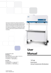
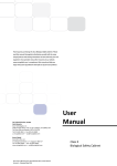
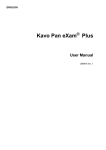
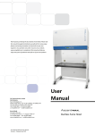
Esco Technologies, Inc. 2940 Turnpike Drive, Units 15-16 • Hatboro, PA 19040, USA Toll-Free USA and Canada 1-877-479-3726 Tel 215-441-9661 • Fax 215-441-9660 us.escoglobal.com • [email protected] Esco Micro Pte. Ltd. 21 Changi South Street 1 • Singapore 486 777 Tel +65 6542 0833 • Fax +65 6542 6920 www.escoglobal.com • [email protected] User Manual Labculture•PLUS Copyright Information © Copyright 2011 Esco Micro Pte. Ltd. All rights reserved. The information contained in this manual and the accompanying product is copyrighted and all rights are reserved by Esco. Esco reserves the right to make periodic minor design changes without obligation to notify any person or entity of such change. Labculture® and Sentinel™ are registered trademarks of Esco. “Material in this manual is provided for informational purposes only. The contents and the product described in this manual (including any appendix, addendum, attachment or inclusion), are subject to change without notice. Esco makes no representations or warranties as to the accuracy of the information contained in this manual. In no event shall Esco be held liable for any damages, direct or consequential, arising out of or related to the use of this manual.” i Table of Contents INTRODUCTORY PAGES i iii v v v v v vii Table of Contents Warranty Terms and Conditions Introduction 1. Products Covered 2. Safety Warning 3. Limitation of Liability 4. European Union Directives on WEEE and RoHS Declaration of Conformity USER SECTION 1 1 Chapter 1 - Product Information 1.1 Quick View 3 Chapter 2 - Sentinel Control System 3 4 4 5 6 7 7 2.1 Sentinel Control System 2.2 Menu Options 2.2.1 Settings 2.2.2 Calibration 2.2.3 Admin 2.2.4 Set Mode 2.3 Alarm and Warnings 9 9 9 9 10 10 10 10 10 11 12 12 15 15 16 Chapter 3 - Basic Cabinet Operation 3.1 Sash Window Operation 3.1.1 Sash Window State 3.1.2 Operating Motorized Sash Window 3.1.3 Using Sash Window 3.2 Starting and Shutting Down the BSC 3.2.1 Turning on the BSC 3.2.2 Turning off the BSC 3.3 Working in the BSC 3.4 Working Ergonomics 3.5 UV Lamps 3.6 Decontamination and Disinfecting Agents Chapter 4 - Maintenance 4.1 Scheduled Maintenance 4.2 Maintenance/Service Log APPENDIX Class II Microbiological Safety Cabinet ii Labculture•PLUS iii Warranty Terms and Conditions Esco products come with either a 1, 2 or 3 year limited warranty, depending on the product purchased, beginning on the date of shipment from any Esco international warehousing location. To determine which warranty applies to your product, refer to the appendix below. Esco's limited warranty covers defects in materials and workmanship. Esco's liability under this limited warranty shall be, at our option, to repair or replace any defective parts of the equipment, provided if proven to the satisfaction of Esco that these parts were defective at the time of being sold, and that all defective parts shall be returned, properly identified with a Return Authorization. This limited warranty covers parts only, and not transportation/insurance charges. This limited warranty does not cover: Freight or installation (inside delivery handling) damage. If your product was damaged in transit, you must file a claim directly with the freight carrier. Products with missing or defaced serial numbers. Products for which Esco has not received payment. Problems that result from: o External causes such as accident, abuse, misuse, problems with electrical power, improper operating environmental conditions. o Servicing not authorized by Esco. o Usage that is not in accordance with product instructions. o Failure to follow the product instructions. o Failure to perform preventive maintenance. o Problems caused by using accessories, parts, or components not supplied by Esco. o Damage by fire, floods, or acts of God. o Customer modifications to the product Consumables such as filters (HEPA, ULPA, carbon, pre-filters) and fluorescent / UV bulbs. Esco is not liable for any damage incurred on the objects used on or stored in Esco equipment. If the objects are highly valuable, user is advised to have in place independent external preventive measures such as connection to a centralized alarm system. Factory installed, customer specified equipment or accessories are warranted only to the extent guaranteed by the original manufacturer. The customer agrees that in relation to these products purchased through Esco, our limited warranty shall not apply and the original manufacturer's warranty shall be the sole warranty in respect of these products. The customer shall utilize that warranty for the support of such products and in any event not look to Esco for such warranty support. Esco encourages all users to register their equipment online at www.escoglobal.com/warranty or complete the warranty registration form included with each product. ALL EXPRESS AND IMPLIED WARRANTIES FOR THE PRODUCT, INCLUDING BUT NOT LIMITED TO ANY IMPLIED WARRANTIES AND CONDITIONS OF MERCHANTABILITY AND FITNESS FOR A PARTICULAR PURPOSE ARE LIMITED IN TIME TO THE TERM OF THIS LIMITED WARRANTY. NO WARRANTIES, WHETHER EXPRESS OR IMPLIED, WILL APPLY AFTER THE LIMITED WARRANTY PERIOD HAS EXPIRED. ESCO DOES NOT ACCEPT LIABILITY BEYOND THE REMEDIES PROVIDED FOR IN THIS LIMITED WARRANTY OR FOR SPECIAL, INDIRECT, CONSEQUENTIAL OR INCIDENTAL DAMAGES, INCLUDING, WITHOUT LIMITATION, ANY LIABILITY FOR THIRDPARTY CLAIMS AGAINST YOU FOR DAMAGES, FOR PRODUCTS NOT BEING AVAILABLE FOR USE, OR FOR LOST WORK. ESCO'S LIABILITY WILL BE NO MORE THAN THE AMOUNT YOU PAID FOR THE PRODUCT THAT IS THE SUBJECT OF A CLAIM. THIS IS THE MAXIMUM AMOUNT FOR WHICH ESCO IS RESPONSIBLE. Class II Microbiological Safety Cabinet iv These Terms and Conditions shall be governed by and construed in accordance with the laws of Singapore and shall be subject to the exclusive jurisdiction of the courts of Singapore. Technical Support, Warranty Service Contacts USA: 1-877-479-3726 Singapore: +65 65420833 Global Email Helpdesk: [email protected] Visit http://www.escoglobal.com/ to talk to a Live Support Representative Distributors are encouraged to visit the Distributor Intranet for self-help materials. Product Appendix, Warranty Listings Biological Safety Cabinets, Laminar Flow Cabinets, HEPA-Filtered Cabinets (except Streamline brand) Laboratory Fume Hoods Ductless Fume Hoods Cleanroom Equipment Laboratory Ovens and Incubators CO2 Incubators Containment/Pharma Products Ultralow Temperature Freezer The warranty periods for BSC may vary by country. Contact your local distributor for specific warranty details. 2 years limited. 4 years limited for Ascent Opti, 6 years for Ascent Max. 1 year limited. 1 year limited. 2 years limited. 2 years limited. 3 years limited. 60 months on Compressor. The warranty period starts two months from the date your equipment is shipped from Esco facility for international distributors. This allows shipping time so the warranty will go into effect at approximately the same time the equipment is delivered to the user. The warranty protection extends to any subsequent owner during the warranty period. Distributors who stock Esco equipment are allowed an additional four months for delivery and installation, providing the product is registered with Esco. User can register product online at www.escoglobal.com/warranty or complete the warranty registration form included with each product. st Policy updated on 1 December 2011 (This limited warranty policy applies to products purchased on or after st 1 January 2012) Labculture•PLUS v Introduction 1. Products Covered Electrical Rating 220-240 V AC, 50Hz, 1Φ Esco Labculture Plus, Class II Microbiological Safety Cabinet 1.2 meters (4 feet) LP2-4D1 2. Safety Warning Anyone working with, on or around this equipment should read this manual. Failure to read, understand and follow the instructions given in this documentation may result in damage to the unit, injury to operating personnel, and / or poor equipment performance. Any internal adjustment, modification or maintenance to this equipment must be undertaken by qualified service personnel. The use of any hazardous materials in this equipment must be monitored by an industrial hygienist, safety officer or some other suitably qualified individual. Before you process, you should thoroughly understand the installation procedures and take note of the environmental / electrical requirements. In this manual, important safety related points will be marked with the symbol. If the equipment is used in a manner not specified by this manual, the protection provided by this equipment may be impaired. 3. Limitation of Liability The disposal and / or emission of substances used in connection with this equipment may be governed by various local regulations. Familiarization and compliance with any such regulations are the sole responsibility of the users. Esco’s liability is limited with respect to user compliance with such regulations. 4. European Union Directive on WEEE and RoHS The European Union has issued two directives: • Directive 2002/96/EC on Waste Electrical and Electronic Equipment (WEEE) This product is required to comply with the European Union’s Waste Electrical & Electronic Equipment (WEEE) Directive 2002/96/EC. It is marked with the following symbol: Esco sells products through distributors throughout Europe. Contact your local Esco distributor for recycling/disposal. • Directive 2002/95/EC on Restriction on the use of Hazardous Substances (RoHS) With respect to the directive on RoHS, please note that this hood falls under category 8 (medical devices) and category 9 (monitoring and control instruments) and is therefore exempted from requirement to comply with the provisions of this directive. Class II Microbiological Safety Cabinet vi Labculture•PLUS vii Declaration of Conformation In accordance to EN ISO/IEC 17050-1:2010 We, of Esco Micro Pte. Ltd. 21 Changi South Street 1 Singapore, 486777 Tel: +65 6542 0833 Fax: +65 6542 6920 declare on our sole responsibility that the product: Category : Class II Microbiological Safety Cabinet Brand : Labculture Plus Model : LP2-4D1 in accordance with the following directives: 2006/95/EEC : The Low Voltage Directive and its amending directives 92/31/EEC : The Electromagnetic Compatibility Directive and its amending directives has been designed to comply with the requirement of the following Harmonized Standard: Low Voltage : EN 61010-1:2010 EMC : EN 61326-1:2006 Class B Design/ : EN 12469 (2000) Class II Biological Safety Cabinet Performance Criteria More information may be obtained from Esco’s authorized distributors located within the European Union. A list of these parties and their contact information is available on request from Esco. _______________________________ XQ Lin Group CEO, Esco This Declaration of Conformity is only applicable for 230V AC 50/60Hz units Class II Microbiological Safety Cabinet viii Labculture•PLUS 1 Chapter 1 - Product Information 1.1 Quick View 1 7 8 2 3 4 6 9 5 1. 2. 3. 4. 5. 6. 7. 8. 9. Optional exhaust collar Frameless shatter proof motorized sash Universal electrical outlet Raised armrest Multi-piece work surface Service fixtures Hinged front panel Esco Sentinel microprocessor control system Optional support stand Class II Microbiological Safety Cabinets 2 Labculture•PLUS 3 Chapter 2 – Sentinel Control System 2.1 Sentinel Control System LCD Display Visual Alarm Up Button Down Button Menu Button Set/Mute/ Diag Button Fan Button Lamp Button Gas/Socket Button UV Button 1. Fan Button o Turns on and turn off the fan. 2. Lamp Button o Turns on and turn off the fluorescent lamps. 3. Socket Button o Turns on and turn off the electrical socket (retrofit kit). o Turns on and turn off the solenoid valve of the gas connection (retrofit kit). 4. UV Button o Turns on and turn off the UV lamp. o UV lamp can only be activated when the sash window is fully closed. Since the sash is capable of filtering UV rays, users are protected from the harmful UV radiation. 5. Up (▲) and Down (▼) Arrow Button o Move the menu options upwards and downwards. o Increase and decrease corresponding value inside one of the menu options. o Move the sash window upward and downward 6. Set or Mute or Diagnostic Button o Proceed to the next step, level or sequence inside the menu options. o To mute the fully opened sash and airfail alarm sound o Enter diagnostic mode 7. Menu Button When you are entering menu options, the alarm will sound to indicate that the microprocessor is not monitoring the operation of the cabinet. No further warnings will be given. o o o To enter and exit from the menu options. To go back to the previous level of the menu options. To access maintenance mode from error condition. Class II Microbiological Safety Cabinets 4 2.2 Menu Options Please refer to the following diagram for complete reference to all menu options available. SETTINGS SET TIME HH:MM WARM UP XX MINUTES POSTPURGE XX MINUTES UV TIMER HH:MM VELOCITY UNIT FPM | M/S TEMP UNIT CELCIUS | FAHRENHEIT SET CONSTANT CALIBRATION ZERO SENSOR CALIB SENSOR MENU NEW ADMIN PIN XXXX (Default 0009) NEW FAN PIN XXXX (Default 0000) A/F MONITOR ENABLE | DISABLE ADMIN RESET B/H/M RESET UV/H/M RESET DEFAULT ALM MUTE DURATION RESET CYCLE SET SASH CYCLE INPUT CYCLE NORMAL SET MODE MAINTENANCE 2.2.1 Settings The user may use the settings menu function to customize the operation of the Cabinet to meet specific application requirements. 2.2.1.1 Set Clock (Time) Users can set the time by increasing/decreasing the hour and minute values. The correct time will be maintained even after the unit is turned off. MENU SETTINGS Labculture•PLUS SET TIME HH:MM 5 2.2.1.2 Warm Up Timer There will be a period of warm-up, before the fan is fully functioning. This is to ensure that the sensors, the fan, and the control system are stabilized, as well as purging the work zone of contaminants. The default setting is 3 minutes and user can set it up to 15 minutes. MENU SETTINGS WARM UP XX MINUTES 2.2.1.3 Post Purge Timer After the user switches off the fan, there will be a period of post-purge. This feature is to ensure that all residual contaminants are purged from the work zone. The default setting is zero minute and user can set it from zero minute to 15 minutes. Setting it to zero minute will disable this feature. However, it is recommended to purge the Cabinet by leaving the fan on for around 3 minutes after the work is complete. MENU SETTINGS POSTPURGE XX MINUTES 2.2.1.4 UV Timer To switch off the UV lamp automatically after a fixed period, UV TIMER menu can be used. The UV TIMER can be set up to 18 hours. By default, this feature is disabled. UV lamp, then, has to be switched off manually. Esco does not recommend that you leave the UV lamp on for more than 60 minutes or overnight as it shortens the lifespan of the UV lamp. MENU SETTINGS UV TIMER HH:MM 2.2.1.5 Airflow Unit Selection Using this option, you can select the unit in which air velocity is measured and displayed. You can choose between meter per second (m/s) and feet per minute (fpm). When the fan is running and also during the calibration process, airflow measurement is displayed in the selected unit. FPM MENU SETTINGS VELOCITY UNIT M/S 2.2.1.6 Temperature Unit Selection Using this option, you can select the unit in which temperature is measured and displayed. You can choose between Celsius and Fahrenheit. The exhaust temperature is displayed in the selected unit. CELSIUS MENU SETTINGS TEMP UNIT FAHRENHEIT 2.2.2 Calibration The purpose of calibration is to ensure the accuracy of the airflow display and alarm (if present). This involves measuring airflow with reference instrumentation and establishing reference between airflow sensor(s) on the Cabinet to the standard reference. Calibration should only be carried out by trained personnel. SET CONSTANT MENU CALIBRATION ZERO SENSOR CALIB SENSOR 2.2.2.1 Set Constant Every sensor manufactured by Esco has a specific Sensor Constant which is used for temperature compensation performed by the temperature sensor. 2.2.2.2 Zero Sensor This option is to let the controller record the specific sensor output voltage and correspond it to 0 m/s or 0 fpm. Class II Microbiological Safety Cabinets 6 2.2.2.3 Calib Sensor This option allows proper calibration and operation of the airflow sensor alarm. There will be three points to be calibrated, namely inflow fail point, inflow nominal point, and downflow nominal point. 2.2.3 Admin The admin menu allows you to change both Fan and Admin. PIN, also to disable it (not recommended). The reset blower hour meter and reset UV hour meter functions are usually used after you change the filter and UV lamp. While the reset default function will return the options in the settings menu to their factory settings. 2.2.3.1 New Admin. PIN Admin. PIN restricts access to MENU functions, including service functions, like calibration. User must enter four digits PIN before accessing MENU. Admin. PIN has higher priority and can be used to control the fan (override Fan PIN). Setting PIN to 0000 will disable this feature. MENU ADMIN NEW ADMIN PIN XXXX 2.2.3.2 New Fan PIN Fan PIN restricts access to fan control. User must enter four-digit PIN before switching fan on or off. As such, it can restrict access to operating the Cabinet by unauthorized personnel. It will also prevent unauthorized shutdown of the Cabinet when continuous operation is required. Note that continuous operation is recommended for better safety. Fan PIN is also needed to disable the alarm when the sash is fully raised and cleaning needs to be performed. Setting the PIN to 0000 will disable this feature. MENU ADMIN NEW FAN PIN XXXX 2.2.3.3 A/F Monitor Whenever the air velocity falls below the fail point, the air fail alarm will be triggered. This option is used to enable/ disable alarm. DISABLE MENU ADMIN A/F MONITOR ENABLE 2.2.3.4 Reset Blower Hour Meter This option is used to reset the blower hour meter. The blower hour meter indicates how long the blower has been in operation. The value can also provide some help in setting up maintenance schedule, including filter change. MENU ADMIN RESET B/H/M 2.2.3.5 Reset UV Hour Meter This option is used to reset the UV hour meter. The UV hour meter indicates how long the UV lamp has been used. Maximum counter is set at 9999 hours. The counter value can be checked while in maintenance mode. Please reset the UV hour meter after each UV replacement. MENU ADMIN RESET UV/H/M 2.2.3.6 Reset Default User can reset the default setting by choosing this option. The features being reset are warm-up period (3 minutes), post-purge period (0 minute), UV timer (0 minute), airflow unit (Metric), temperature unit (Celsius), Admin. PIN (0009), and Fan PIN (0001). Note that the calibration settings cannot be reset as it may cause the Cabinet to operate in an unsafe manner. The hour meters cannot be reset either. MENU ADMIN Labculture•PLUS RESET DEFAULT 7 2.2.3.7 Alarm Mute Duration To mute airfail alarm for a certain period. The mute period can be set between 0 to 299 seconds, the default value is 30 seconds. MENU ADMIN ALM MUTE DURATION XXX 2.2.3.8 Set Sash Cycle To reset the sash cycles count to zero or to input the sash cycle count manually. The maximum of value of sash cycles is 16000. The cycles will raise every sash move to up and down. RESET CYCLE MENU ADMIN SET SASH CYCLE INPUT CYCLE Warning message will be showed after the cycle value reach 15000. 1st warning: “Replace Sash Motor” – after sash reached 15000 cycles. 2nd warning: “Stop Using Sash” - after sash reached 15500 cycles. 3rd warning: “Sash Motor Locked” (sash motor cannot operate) - after sash reached 16000 cycles. 2.2.4 Set Mode Cabinet has two working mode, the default normal mode which is used in a day to day activity, and maintenance mode. NORMAL MENU SET MODE MAINTENANCE 2.2.4.1 Normal Mode Every time the Cabinet is restarted, this mode will be activated by default. In this mode, all alarms and interlocks are enabled. 2.2.4.2 Maintenance Mode Maintenance mode should only be accessed by qualified personnel during maintenance. In this mode, all alarms are disabled and all interlocks are defeated. 2.3 Alarms and Warnings MSC uses alarms to indicate that the condition inside the MSC is not safe for the operator, so check the LCD display to understand the cause of these alarms. The most common alarm is the SASH ALARM that indicates that the sash is neither at the normal operating height nor at fully closed position (UV mode) – this condition can easily be corrected by putting the sash at the appropriate operation position. Another warning that should be acted upon is AIR FAIL! which indicates that there is airflow failure. The operator should check if there is any obstruction to the airflow, and correct it if possible. However, if the problem continues, the operator should stop working as the MSC’s protection may have been compromised. Call service or Esco’s local distributor. Other alarms that indicate a failure or an error in the MSC system: • ERR.AIRFAIL will be displayed if the blower is turned off while there is an airflow failure. • ERR.MSWITCH will be displayed if the microprocessor (controller) detects more than one microswitch activated at the same time, which is impossible, as the sash can only be at one position at one time. This indicates a failure in the sash detection system. • ERR.CALIB will be displayed if the airflow velocity sensor is not yet calibrated. Class II Microbiological Safety Cabinets 8 Labculture•PLUS 9 Chapter 3 – Basic Cabinet Operation 3.1 Sash Window Operation 3.1.1 Sash Window State Sash is fully open Sash is in safe position Sash is fully closed Blower can be active Fluorescent lights can be used Unsafe working condition Blower can be activated Fluorescent lights can be used Safe working condition Blower can’t be activated Fluorescent lights unusable 3.1.2 Operating Motorized Sash Window The motorized sash uses a “push and hold” mechanism, so if you remove your finger from the button the sash will stop immediately – this is a safety feature to control the closure and prevent anything getting trapped in the aperture as the sash descends. Lower Sash from Fully Open Position When the sash is fully open, pressing the down button and holding it will cause the sash to move to the Safe Height setting and stop. If the fluorescent lights are on as the sash descends, they will stay on as long as the sash stops in the Safe Position (not applicable for NC2). If you release the button before the sash has reached Safe Position the lights will switch off automatically. Lower Sash from Safe Height Position When the sash is at safe operating height pressing the down button and holding it will cause the sash to move down to the fully closed position and stop. If the fluorescent lights are on as the sash descends, they will switch off automatically as soon as the sash reaches fully closed. If you release the button before the sash has reached the fully closed position the lights will switch off automatically Raise Sash from Fully Closed Position When the sash is fully closed, pressing the up button and holding it will prompt the user to input the password to turn on the fan. If the password is correct, if it was on fan will turn on and the sash will move up to the Safe Height setting and stop. Raise Sash from Safe Height Position When the sash is safe operation position, pressing the up button and holding it will cause the sash to move up to the fully open position and stop. If the fluorescent lights are on as the sash rises, they will stay on as long as the sash is allowed to fully open. Stopping the sash midway will cause the lights to switch off automatically. Class II Microbiological Safety Cabinets 10 3.1.3 Using Sash Window The sash window should be fully closed when the cabinet is not in use. This helps keep the work zone interior clean. The sash window should always be in the normal operating height at all times when the cabinet is in use. Even if the cabinet is left unattended, but the blower is on, the sash window should never be moved from the normal operating height, unless during loading or unloading of materials/apparatus into the cabinet. The alarm will be activated whenever the sash window is moved from the normal operating height. Whenever the sash window is moved to the correct height from a higher or lower position, the light will automatically be turned on as a signal to the user. The sash window may be opened to its maximum position for the purpose of loading/unloading of materials/apparatus into the cabinet. When the sash window is fully opened, the alarm sound may be muted by pressing MUTE button but, will be automatically sounded again after 5 minutes to remind the user that it is not safe to work in the cabinet and the light will be turned on to facilitate cleaning. 3.2 Starting and Shutting Down the MSC 3.2.1 Turning on the MSC 1. 2. 3. Raise the sash to the indicated normal operational height (READY state). The lamp will turned on when this height is reached. Turn on the fan by pressing the FAN button. Input the Fan PIN if asked (if PIN ≠ 0000). This will start the warm up procedure (default: 3 minutes). All buttons are diabled during warm up period. The MSC is ready for work. 3.2.2 Turning off the MSC 1. 2. 3. Turn off the fan by pressing the FAN button. Input the Fan PIN if asked (if PIN ≠ 0000). This will start the post purge procedure (default: 0 minute). All buttons are diabled during post purge period. Lower the sash to the fully closed position (the display will show UV MODE). The sash can be lowered immediately after turning off the fan as it will not interrupt the post purge procedure. Turn on the UV lamp (when present) to decontaminate the work area by pressing the UV button. Leave the UV lamp on to make sure the decontamination is done effectively . The UV lamp can only be turned on after the post purge procedure is finished. 3.3 Working in the MSC Surface-decontaminate the work area (work surface, back and side wall, UV lamp, electrical outlet, service fixture and the inner surface of the sash window) before and after using the MSC. Allow the MSC to purge any contaminant by allowing the blower to operate at least 3 minutes before and after using the MSC. Surface-decontaminate any item (including your arms) or apparatus with appropriate disinfectant before entering or exiting the work area. Place the waste container (containment bag, pippete discard pans, etc.) inside the MSC work area. Place all items and apparatus in the safe working area. Safe Working Area for Multi Tray MSC Labculture•PLUS 11 Minimize room activity (personnel movements, closing and opening of doors, etc.) since these external airflow disturbances may adversely affect the MSC’s internal airflow, thereby possibly impairing the containment capabilities of the MSC. Ensure that the sash is at normal operating height (READY state) before starting any experiment. Ensure the front and back air grilles are not obstructed by your arms or any other objects. Work as far inside the MSC as possible - at least 150 mm (6 inches) behind the front air intake grille. While working in the MSC, move your hands slowly and in a controlled manner. Rapid movements may disrupt the air barrier, allowing contaminants to escape or enter the MSC. The use of Bunsen burner inside the work zone is not recommended. However if the use of Bunsen burner is unavoidable, place the burner in the right side of the work zone. Place aerosol-generating instruments as far inside the MSC as possible and at least 150 mm (6 inches) from clean items/materials. Place air turbulence generating equipment such as centrifuges, blenders or sonicators towards the back of the MSC. Stop other work while any of this equipment is in operation. As far as possible, it is recommended that the MSC be operated continuously in order to achieve optimal containment and cleanliness. Airflow studies have shown that once the fan has been switched off, air from the MSC may escape due to the thermal currents from inside the MSC. 3.4 Working Ergonomics On most occasions, you would most likely be operating the MSC in sitting rather than standing posture. There are some obvious advantages of the sitting posture: The physiological energy cost and fatigue involved in sitting are relatively less Sitting posture provides the body with a stable support However, sitting position has some drawbacks too: The working area available is fairly limited There is a potential risk of being constrained in the same posture for a long time Sitting posture is one of the most stressful postures for one’s back Therefore you should pay careful attention to the following guidelines in order to achieve comfortable and healthy working conditions: Always ensure that your legs have enough legroom. Keep your lower back comfortably supported by your chair. Adjust the chair or use a pillow behind your back whenever necessary. You should place your feet flat on the floor or on a footrest. Don’t dangle your feet and compress your thighs. You should keep varying your sitting position throughout the day at regular intervals so that you are never in the same posture for too long. Observe the following precautions with respect to your eyes: o Give your eyes frequent breaks. Periodically look away from the work area and focus at a distant point. o Keep your glasses clean. Arrange the items/apparatus frequently used in your work in such a way that you can minimize the physical strain involved in handling them. Exercise regularly The MSC’s noise emission has been tested and found to be in compliance with EN 12469, ISO 4871 and NSF/ANSI 49 which is important to ensure health and comfort for the operator. Ergonomics accessories available with Esco include: Armrest padding Lab chair Footrest Please contact your local distributor or Esco for more information. Class II Microbiological Safety Cabinets 12 3.5 UV Lamps 2 The UV light is a germicide and virucide. Even at the minimum acceptable irradiance in a MSC – 40 μW/cm (US Department of Health and Human Services et. al., 2000), it would only take 12.5 minutes to reach 30,000 μW/cm2 (1 W = 1 J/sec), which has been listed as germicidal for spore forming organism. Unlike many other type of decontamination agent, UV light doesn’t leave any residue. The decontamination action stops upon de-energizing of the lamp. However, due to the short wavelength, the UV light does not penetrate well. Thus UV light can only be used to effectively disinfect the work area of an empty MSC. For any container stored inside the MSC’s work area, the UV radiation will only disinfect the outer surface of the material, leaving the inner surface and the content inside the material untouched. UV light decontamination method may be used before and after working with vegetative organisms and viruses. However, it should not be the sole decontamination agent; the use of chemical decontamination agent is still encouraged. Minimize the material inside the MSC’s work area during the process of UV light decontamination. A direct interaction with UV light can degenerate plastic- or rubber-based material and can cause other hazard. Make sure that the MSC sash is in the fully closed position and the interlock is working properly before activating the UV lamp. Avoid direct contact with skin and eyes as UV light is classified as a probable human carcinogen. The UV lamp should be activated for around 60 minutes to work effectively. Use the UV timer feature to easily control the period of decontamination (UV timer is disabled by default). Leaving the UV lamp on for over 60 minutes or even overnight is not recommended because it shortens the lifespan of the lamp. The UV lamps used in Esco MSC have a lifespan of 2,000 hours. The UV lamp should be cleaned of any dust and dirt weekly and changed annually to ensure its effectiveness. The use of UV lamp in MSC has been explicitly discouraged in all major international standards and recommendations. 3.6 Decontamination and Disinfecting Agents For stainless steel surfaces, all common disinfecting agents except chlorine-based ones are suitable. For powder coated surfaces, all common disinfecting agents are suitable. However, the MSC has been specifically evaluated for use with the following: o 1N hydrochloric acid o 1N sodium hydroxide o 1% quaternary ammonium compound o 5% formaldehyde o 5,000 ppm hypochlorite o 2% iodophor o 5% phenol o 70% ethyl alcohol Depending on the contaminant involved at the time of operating the MSC, there are various other types of disinfecting agents that may be used. The following table outlines the effectiveness of various disinfecting agents against the different types of contaminants. Labculture•PLUS 13 Decontaminant Glutaraldehyde Peroxide/ Paracetic acid/ Acetic acid Chlorine Dioxide Chlorine Iodophor Alcohol Phenolic Quaternary Ammonium Compounds Classification Sterilant Sterilant Sterilant High Level Intermediate Intermediate Intermediate Low Level 2% 10-600 + 1% 10-720 0.01-0.1% 10-600 + 0.01-5% 10-30 0.5-2.5% 10-30 + 70-85% 10-30 + 0.2-3% 10-30 + 0.1-2% 10-30 + + + + + + + + + + + + + + + + +/+ + + + +/+ + + +/+ + + +/+ + + + + + + + +/- + Parameters for use: Concentration Contact time (min.) Stability > 1 week (1) Agents: Bacterial Endospores Naked Viruses Mycobacterium Vegetative Bacteria Enveloped Viruses Characteristics: Inactivated by Organics Residual Corrosive Flammable Skin Irritant Eye Irritant Respiratory Irritant Toxic Use in MSCs: Routine Surface Decon Biohazardous Spill + + + + + +/+ + + + + + + + + + + + + + + + + + + + + + + + + + + + +/- + + +/- + +/- + + + + +/+ + + +/- + (1) protected from light and air + = effective, +/- = results may vary, blank = not effective Decontamination Decontamination may frequently be carried out by means of formaldehyde fumigation or using other decontamination agents, such as chlorine dioxide or hydrogen peroxide. Decontamination process should only be carried out by trained personnel. In any of the following eventualities, the user should ensure that the MSC has been properly decontaminated, keeping in mind the nature of the pathogens used: At the time of moving/relocating the MSC At the time of changing the type of work being carried out in the MSC Before accessing contaminated areas for servicing, for example - filter replacement Class II Microbiological Safety Cabinets 14 Labculture•PLUS 15 Chapter 4 –Maintenance 4.1 Scheduled Maintenance Proper and timely maintenance is crucial for trouble free functioning of any device and your Esco MSC is no exception to this rule. We strongly recommend that you follow the maintenance schedule suggested hereunder in order to obtain optimal performance from your Esco MSC. No. Description of Task to Perform 1 2 3 4 5 6 7 8 9 10 11 12 Surface decontaminate the work zone MSC power-up alarm verification Thoroughly surface decontaminate the drain pan Check the paper catch for retained materials Clean the exterior surfaces of the MSC Clean the sash window Check all service fixtures (where present) for proper operation Inspect the MSC for any physical abnormalities or malfunction Clean up stainless steel surfaces with MEK Re-certification Change UV Lamp (where present) Change the fluorescent lamps Day √ √ Maintenance to be carried out every Week Month Quarter 1 Year 2 Years √ √ √ √ √ √ √ √ √ √ Cleaning the MSC Clean the work surface and walls with appropriate disinfectant agent and soap water afterward Clean the sash window using an appropriate disinfectant agent and glass cleaner afterward Use a damp cloth to clean the exterior surface of the MSC, particularly on the front and top in order to remove dust that accumulated there Use clean water to finish the cleaning and wash away any residue of disinfectant agent, soap water and glass cleaner For removing stubborn stains or spots on the stainless steel surface, make use of MEK (Methyl-EthylKetone). In such cases, make sure that you wash the steel surface immediately afterwards with clean water and some liquid detergent. Use a polyurethane cloth or sponge for washing. Regularly cleaning the stainless steel surface can help you retain the attractive factory finish. Test the audible and visual alarm The simplest method by far would be to move the sash until the glass window is no longer in the sash ready or UV mode position. Check the cabinet’s functionality Check the MSC’s mechanical functionality; ex: sash window – lubricate if necessary Check the MSC’s electrical functionality; ex: fluorescent lamp – replace if necessary Check the MSC for any defect, repair immediately Re-certification All MSC must be re-certified annually by a certified engineer. See test report for recertification procedure. Class II Microbiological Safety Cabinets 16 Accessing the paper catch The purpose of accessing the paper catch is to remove any retained materials that might cause obstructions. Care must be taken as the area is contaminated. Before opening the paper catch: Use appropriate personal protective equipment (PPE). Wipe down the interior of the MSC including the top and bottom surfaces of the work tray(s) while airflow is operating. If the interior cannot be wiped down, the MSC should be decontaminated Accessing the paper catch 1. Turn the blower off. Then raise the sash to fully open position for easy access. 2. Remove the tray(s) to access the paper catch. 3. The figure beside, points to the location of the paper catch. Locate and remove any material trapped. Be careful of any sharp objects that might be present. You might want to use a mirror to help you see better. Sash cleaning procedure for motorized sash MSC 1. Remove armrest 2. Press MENU button, select SET MODE then choose MAINTENANCE MODE - this mode allows you to lower the sash further than usual 3. Lower the sash by pressing the DOWN button continuously until the sash is in the lowest position and create a 10 cm opening between the sash and the diffuser 4. Open the front panel. 5. Slide your hand through the opening and clean the inner side of the sash using cloth and IPA 70% 6. After cleaning, push the UP button continuously until the sash is in the sash ready position 7. Close the front panel. 8. Reattach armrest 9. Set the cabinet back to NORMAL MODE 4.2 Maintenance/Service Log It is good practice (and in some cases regulatory requirement) to maintain a log of all maintenance work carried out on your cabinet. Labculture•PLUS APPENDIX LOG RECORD Cabinet Serial Number Person in Charge 1. 2. 3. Date : : : _______________________________________________________________ _______________________________________________________________ _______________________________________________________________ This log record should be used by the operator to record any new agent/virus/bacteria/germs that has been introduced to the cabinet during its operation, problems encountered, etc. Any decontamination procedure performed by either the user or the technician should be recorded down as well. Please also record any major maintenance procedure performed by the service technician, for example: parts replacement, recertification, etc. Event User Signature Supervisor Signature In case of emergencies, please call: Name : _______________________________________________________________ Cell Phone Number : _______________________________________________________________ E-mail : _______________________________________________________________