1
RL78/G13
Basic Initialisation for Cubesuite+ and IAR Toolchain
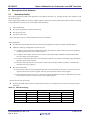
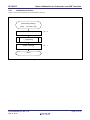
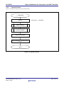
Setting up ports for switches
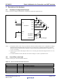
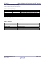
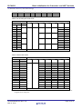
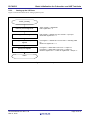
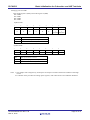
• Port mode register 5 (PM5)
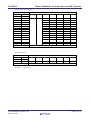
• Pull-up resistor option register 0 (PU0)
P50: SW1 P51: SW2
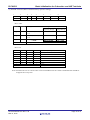
• Port mode control register 0 (PMC0)
Digital input
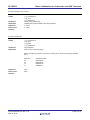
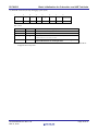
Symbol: PM5
7
6
5
4
3
PM57
PM56
PM55
PM54
0
0
0
0
2
1
0
PM53
PM52
PM51
PM50
0
0
1
1
(See LED1) (See LED0)
PM5n
PM5n pin I/O mode selection.
0
Output mode (output buffer on)
1
Input mode (output buffer off)
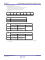
Symbol: PU5
7
6
5
4
3
2
1
0
0
PU56
PU55
PU54
PU53
PU52
PU51
PU50
0
0
0
0
0
0
1
1
PU0n
Selection of on-chip pull-up resistor for P0n pin.
0
On-chip pull-up resistor not connected.
1
On-chip pull-up resistor connected.
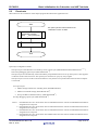
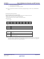
Notes 1. This sample code configures any unused ports for output to minimize the adverse influence of through
current.
2. For details on the procedure for setting up the registers, refer to RL78/G13 User's Manual: Hardware.
R01AN1083EG0100 Rev.1.00
Mar 13, 2012
Page 22 of 31