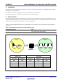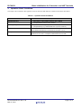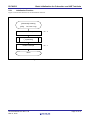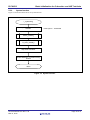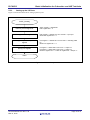
1
RL78/G13
5.
Basic Initialisation for Cubesuite+ and IAR Toolchain
Description of the Software
5.1
Operation Outline
The sample program described in this application note initializes the CPU (e.g., selecting the CPU clock frequency) and
sets up its I/O ports.
After completing the hardware setup, the sample program controls the on/off of three LEDs (LED1 to LED3) according
to the combination of states of two switch inputs (SW1 and SW2).
(1)
CPU initialization*
z
Sets up the peripheral I/O redirection function.
z
Sets up the I/O ports.
z
Sets up the CPU clock.
Note: The option bytes are referenced before the CPU is initialized.
<Setup conditions>
z
Sets the reset value because the CPU does not use the peripheral I/O redirection function (PIOR register).
z
Makes the following configurations for the I/O ports:
(1) Configures the ports that are configured for analog input after the release of the reset state for digital I/O
(ADPC register and port mode control register).
(2) Configures P50 and P51 which are to be used as switch inputs (SW1 and SW2) for input and the other
ports for output (port mode register).
(3) Connects on-chip pull-up resistors to P50 and P51 which are to be used as switch inputs (SW1 and SW2)
(pull-up resistor option register).
(4) Sets P53, P62, P63 which are to be used for on/off control of LEDs (LED1 to LED3) to 1 and the other
unused pins to 0 (port register).
z
Sets up the CPU clock.
(1) Sets the reset value because the high-speed system clock and subsystem clock are not to be in use (clock
operation mode control (CMC) register and clock operation status control (CSC) register).
(2) Selects the main system clock (fMAIN) as the CPU/peripheral hardware clock (fCLK) and HOCO (fIH) as the
main system clock (fMAIN) (system clock control (CKC) register).
(2) Executes the main processing.
z
Performs the LED output control as summarized in Table 4.1 according to the state of the switch inputs (SW1
and SW2).
Table 4.1 Main Processing
Switch Input
LED Output
SW1 (P50)
SW2 (P51)
LED1 (P53)
LED2 (P62)
OFF
OFF
OFF
OFF
ON
OFF
ON
OFF
OFF
ON
OFF
ON
ON
ON
OFF
OFF
Note: Refer to RL78/G13 User's Manual for notes on device use.
R01AN1083EG0100 Rev.1.00
Mar 13, 2012
LED3 (P63)
OFF
OFF
OFF
ON
Page 6 of 31