1
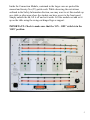
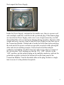
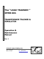
The “LOAD TRAINER®”
XFMR-001
TRANSFORMER TRAINER &
SIMULATOR
Operation &
Maintenance
Manual
Rev. 2
UTILITY SOLUTIONS, INC.
101 33rd St. Drive SE
Hickory, NC 28602
Phone (828) 323-8914
Fax
(828) 323-8410
[email protected]
www.utilitysolutionsinc.com
SECTION 1: SAFETY INFORMATION
™
The LOAD-TRAINER Transformer Trainer & Simulator is a fully functional
electrical trainer allowing simulation of most distribution transformer
connection schemes. This device contains actual transformers that completely
duplicate in-field situations.
DANGER
!
HIGH VOLTAGE
Warning
Voltages can reach high levels and may cause electrical shock. Use extreme
caution and treat all wiring, jumpers and ‘banana’ and ‘pin’ jacks as if handling
live conductors. In certain configurations, voltages may exceed 480 Volts. For
this reason, the power unit should not be running during hook-up or
configuring the transformer trainer/simulator. Also the power unit’s
components are not rated for continuous duty and may heat up during
prolonged use. Hence the power unit should not be run for extended
periods of time and should only run when taking voltage readings.
In addition to reduce the risk of electrical shocks, fire, etc.:
• Do not remove screws, covers or cabinet. Refer servicing to qualified
personnel.
• Do not expose this device to rain, moisture or combustible materials.
• Select a place that is level, dry and between 41°F and 95°F. Do not place
either unit on a heat generating object.
• Avoid a dusty place or a place subject to vibrations.
• The power cord supplied is configured and rated for standard 120 Volt,
10 Amp receptacles. It is to be used as a disconnect for this device by
unplugging the power cord from the receptacle.
2
SECTION 2: LIST OF COMPONENTS
Qty.
1
1
1
1
8
4
5
5
1
3
Description
Power Supply in Shipping / Presentation Case
Multiple-conductor cord with polarized plug
120 Volt, 10 Amp AC Grounded Power Cord
Connection Module in Shipping / Presentation Case
12” red ‘pin’ patch cords
4” black ‘banana’ patch cords
12” red ‘banana’ patch cords
12” black ‘banana’ patch cords
User Manual
12” black pin patch cords
3
SECTION 3: UNPACKING, SET-UP & INSTALLATION
™
The LOAD-TRAINER Transformer Trainer & Simulator is shipped in two
wheel portable cases containing the (1) Power Supply and the (2) Connection
Module.
4
Inside the Connection Module, contained in the larger case are packed the
manual and twenty-five (25) patch cords. While observing the restrictions
outlined in the Safety Information Section, one may want to set this module up
on a table or other area where the student can have access to the front panel.
Simply unlatch the lid, lift it off and set it aside. Lift the module out and set it
up on the table using the swing-out hinged legs as support.
IMPORTANT: Check to make sure that the ‘ON – OFF’ switch is in the
‘OFF’ position.
5
Next unpack the Power Supply.
Inside the Power Supply, contained in the smaller case, there is a power cord
and a multiple-conductor cord fitted with a polarized plug. If the banana plugs
are stored in the Power Supply, make sure to use a bag because they can fall
down behind the red cover and cause damage during operation. Because of the
weight and noise, one may want to keep the Power Supply on the floor next to
the Connection Module. Unlatch and set aside the lid as done before and plug
the male end of the power cord into an agreeable receptacle while placing the
other end into its matching receptor. Unravel and extend the multipleconductor cord making sure that it does not catch on any edges or corners of
the red sub-plate. Now, making sure that the ‘ON – OFF’ switch is in the
‘OFF’ position, put the polarized plug on the multiple-conductor cord into the
polarized receptacle located at the bottom left on the front panel of the
Connection Module. Turn the threaded collar on the plug clockwise a single
turn to secure it to the polarized receptacle.
6
SECTION 4: DESCRIPTIONS & FUNCTIONS
When in use the Power Supply and the Connection Module are connected by
the multiple-conductor cord. This cord is hardwired on one end to the Power
Supply and is fitted with a polarized plug to prevent improper connection to the
Connection Module.
The Power Supply requires 120 Volt, 10 Amp AC grounded power from a
standard (North American) receptacle. A switch located on the front panel of
the Connection Module controls this supply voltage. When this switch is
closed, power flows to an electric motor and also to a 120-to-20 Volt
transformer. The motor is coupled to an automobile alternator that was reconnected to provide a three-phase, four-wire output. The 20 Volt output of the
transformer is rectified and used to excite the rotor of the alternator. A rheostat
mounted on the back panel of the Connection Module provides a degree of
control over the output of the alternator. When the rheostat knob is pointed
toward the word ‘DELTA’ the output voltage of the alternator is
approximately seven (7) Volts phase-to-phase. When the knob points to
‘WYE’ the output voltage is approximately seven (7) Volts phase-to-neutral.
See Equation 1.
Equation 1.
WYE = VPP = !3 • VPN = DELTA
Hence: WYE = VPP = !3 • 7
WYE = VPP " 12
7
It is for this reason that a Delta connected primary wired to a WYE system
voltage can produce secondary voltages much higher than expected. In addition
it may be necessary to fine-tune the rheostat occasionally to obtain the desired
voltage output from the transformers.
The Connection Module, contained in the larger case, has lines at the top of the
panel to represent a three-phase four-wire power system (A, B, C, N). The tip
jacks located on the lines are connected to buss bars within the cabinet. The
three-phase system supply is protected by fast acting thermal circuit breakers
and disconnecting switches. The tip jacks are used to make connections from
the three-phase four-wire power system supply to the primaries of the singlephase transformers located behind the panel.
The three transformer outlines simulate actual transformers located behind the
panel. Connections between the system supply conductors and the red input
terminals (H1 and H2) of the transformer outlines will provide a circuit to the
actual transformers. These connections are made using the red patch cords
equipped with ‘pin’ tip plugs. The plugs can be stacked, if desired.
The transformers have three black unlabeled output terminals. They can be
thought of as X1, X2 and X from left to right respectively, where X2 is neutral
in a 120/240 Volt transformer.
8
The lines at the bottom of the panel represent load lines (N, L1, L2, L3).
Connections between the transformer output terminals and the load lines are
made using the longer red and black banana patch cords. These too can be
stacked if desired. Three short black ‘banana’ patch cords are used to serve as
transformer secondary neutrals to load conductor neutral straps. It is suggested
that all exercises start with these patch cords in place and removed as necessary
for the proper operation of the installation.
A panel-mounted, 0 to 500 Volt, AC meter can be used to measure the
transformer’s output through the load lines or directly using the banana jacks
located directly below it.
Eight (8) toggle switches are located in a recess in the left side of the
Connection Module. The normal position of all these switches is UP, toward
the top of the panel. The switches can be used to introduce problems at the time
of installation or a problem arising after the installation has been in service.
The function of the switches is not indicated on the module. Numbered from
the top-left down to the bottom-right (see Figure 1 below), the functions of the
switches are as follows:
#1
Phase paralleling switch. When this toggle switch is thrown to its down position,
phase ‘A’ is eliminated and the phasing is ‘B-B-C.’
#2
Phase paralleling switch. When the toggle switch is thrown to its down position,
phase ‘C’ is eliminated and the phasing is ‘A-B-B.’
Note: When both toggle switches #1 and #2 are moved to the down position, phases ‘A’
and ‘C’ are eliminated and the phasing is ‘B-B-B.’
#3
Controls the output voltage of transformer #1. In the normal, up position, the right
(X3) secondary terminal will be inactive and 120 Volts will exist between the center
(X2) terminal and the left (X1) terminal. When switch #3 is moved to the center
position there will be no voltage output.
When switch #3 is moved to its down position the voltage is 120 between the center
(X2) and either of the outside secondary terminals (X1 or X3) and between the
outside terminals (X1 and X3) the meter will read 240 Volts.
#4
Polarity reversal switch changes transformer #1 from additive in the up position to
subtractive in the down position
9
#5
#6
Same function as switch #3 except it affects transformer #2.
Same function as switch #4 except it affects transformer #2.
#7
#8
Same function as switch #3 except it affects transformer #3.
Same function as switch #4 except it affects transformer #3.
Top
Switch #1
UP - ABC
DN - BBC
Switch #2
UP - ABC
DN - ABB
Switch #3 Transformer #1
UP – 120 X1-X2
CTR - 0
DN – 240 X1-X3
Switch #4 Transformer #1
UP - Additive Polarity
DN - Subtractive Polarity
Switch #5 Transformer #2
UP – 120 X1-X2
CTR - 0
DN – 240 X1-X3
Switch #6 Transformer #2
UP - Additive Polarity
DN - Subtractive Polarity
Switch #7 Transformer #3
UP – 120 X1-X2
CTR - 0
DN – 240 X1-X3
Switch #8 Transformer #3
UP - Additive Polarity
DN - Subtractive Polarity
Rear
Front
Figure 1
Switch Panel
10
SECTION 5: OPERATION
™
The LOAD-TRAINER Transformer trainer & simulator has the capability to
connect single-phase and the following types of three-phase transformers:
Delta-Delta, Delta-Wye, Open Delta-Open Delta, Wye-Delta, Wye-Wye, Wye
(one leg out)-Open Delta.
To begin connecting transformers follow these general instructions:
1)
Check position of toggle switches on the left side of the Connection
Module. The normal position of all these switches is UP, toward the top
of the panel. Set the disconnecting switches located in the system supply
phase lines to the ‘ON’ position (left) and push to reset any tripped circuit
breakers.
2)
Install the short black transformer secondary neutrals to load conductor
neutral banana patch cords. One or more of these patch cords may have to
be removed for the bank to operate properly.
3)
Choose the type of primary bank to be connected and use the red ‘pin’ tip
patch cords to wire it.
4)
Set rheostat pointer to ‘DELTA’ or ‘WYE’ for desired input (i.e. primary
connection and/or system for transformer).
5)
Make output connections with the red and black banana patch cords,
stacking plugs if desired. Bring leads down to load lines and use a set of
patch cords from the two (2) load lines to be measured to meter’s input
jacks (located below meter).
11
6)
Close the ‘ON – OFF’ power switch. The Power Supply should start and
deliver the proper voltage to the transformers. If an incorrect connection
exists one or more circuit breakers will open. If so shut down the unit
using the power switch and recheck connections.
NOTE:
The power unit should not be operated for extended periods of
time. Run only when taking voltage readings.
7)
If connections have been properly made voltage should appear on the
load lines. These readings should be near normal for the transformer bank
being made. Use the rheostat to make minor adjustments.
8)
Problems can be introduced after the installation has been shown to
operate correctly. This is done by the toggle switches on the left side of
the Connection Module. When introducing problems refrain from giving
information other than to state that an open neutral does not exist. Let the
student solve the problem.
NOTE:
In certain Wye Primary configurations the actual measured device output
voltage is less than the expected output voltage. Therefore the panel meter is
scaled at the factory so the actual measured device output voltage matches the
expected output voltage. An independent meter device may display voltages
that are less than the voltages displayed on the panel meter (in Wye Primary
configurations).
Likewise in certain Delta Primary configurations the actual measured device
output voltage is greater than the expected output voltage. Therefore the panel
meter is scaled at the factory so the actual measured device output voltage
matches the expected output voltage. An independent meter device may
display voltages that are greater than the voltages displayed on the panel meter
(in Delta Primary configurations).
12
SECTION 6: EXAMPLES
Simple Single-Phase Transformer Connections
This is an application that can serve as an introduction to the LOADTRAINER™ Transformer Trainer & Simulator. By following the Operation
instructions above and making connections as described, one can gain a
fundamental understanding of the trainer.
• Begin by following instructions 1 through 3 in Section 5.
• Using the red ‘pin’ tip patch cords connect a single-phase transformer to a
DELTA system primary as shown in Figure 2.
• Set rheostat pointer to ‘DELTA’ per instruction 4. (If primary was installed
on WYE system then rheostat would have to point to ‘WYE’).
• Make output connections with the red and black banana patch cords bringing
leads down to load lines to a 120 Volt WYE secondary as shown in Figure
2. See instruction 5.
• Use a set of patch cords from the two (2) load lines to be measured to the
meter’s input jacks (located below meter).
• Close the ‘ON – OFF’ power switch per instruction 6. The Power Supply
should start and deliver the proper voltage to the transformer. If an incorrect
connection exists one or more circuit breakers will open. If so shut down the
unit using the power switch and recheck connections.
NOTE:
The power unit should not be operated for extended periods of
time. Run only when taking voltage readings.
• If connections have been properly made the meter will indicate voltage
appearing on the load lines. These readings should be near normal for the
transformer bank being created. Use the rheostat to make minor adjustments.
13
The following table summarizes the Connection Diagrams provided on the following pages:
Figure
Figure 2
Figure 3
Figure 4
Figure 5
Figure 6
Figure 7
Figure 8
Figure 9
Figure 10
Figure 11
Simulation
Single Phase Transformer w/ Delta Primary & 120 Volt Wye Secondary
Single Phase Transformer w/ Delta Primary & 120 Volt Delta Secondary
Single Phase Transformer w/ Delta Primary & 120/ 240 Volt Delta Secondary
Three Phase Transformer w/ Delta Primary & 120 / 208 Volt Wye Secondary
Three Phase Transformer w/ Delta Primary & 120 Volt Delta Secondary
Three Phase Transformer w/ Delta Primary & 120 / 240 Volt High Leg B Delta Secondary
Three Phase Transformer w/ Open Delta Primary & 120 Volt Open Delta Secondary
Three Phase Transformer w/ Wye Primary & 120 Volt Delta Secondary
Three Phase Transformer w/ Wye Primary & 120 / 208 Volt Wye Secondary
Three Phase Transformer w/ Wye (One Leg Out) & 120 Volt Open Delta Secondary
14
15
16
17
18
19
20
21
22
23
24
Vector Application to Transformer Connections
™
One feature of the LOAD-TRAINER transformer trainer & simulator is the
vector application to transformer connections. This unit can be used to teach
transformer connections using the vector concept. If desired, the instructor
should apply his own arrows as follows: the vector arrows between the H1 and
H2 terminals should be fixed in position pointing left (from H2 to H1). Vectors
representing the secondary windings can be attached to the front of the panel
pointing right and can be reversed to indicate a change in polarity. Switches #4,
6 and 8 are used to change polarity of the secondary windings. Consult Section
#4: Descriptions & Functions for more information.
Transformer Backfeed
Numerous situations can be duplicated to produce a transformer backfeed. An
example is the lack of grounding on a Wye-Delta bank. To simulate
transformer backfeed connect a Wye-Delta bank (see Figure 9) with the H2
terminals of each transformer connected to each other but floating. Run the unit
to show proper operation. Open one of the disconnecting switches located on
the back panel to the ‘OFF’ position. The indicator light will go off. Repeat this
procedure with the H2 terminals grounded. In this case the open phase will
glow indicating a backfeed.
Parallel Phases
Parallel phases can also be simulated on the TRANSFORMER SIMULATOR.
It is quite possible for a bank connected Wye (one leg out)-Open Delta (see
Figure 11) to become energized from the same phase. In most instances a
jumper on a vertical corner burning into and falling down on the phase below it
causes this. If the bank is connected between these phases this results in the
input windings being in parallel and the output windings still connected in
series. Using normal procedures this produces a situation that is difficult to
troubleshoot. This situation can be duplicated with the use of toggle switches
#1 or #2 or both (Consult Section #4: Descriptions & Functions for more
information). Do not permit the student to measure voltages on the system
supply phases. It would be rare for a trouble-shooter to have the equipment to
measure the phase voltage. Have the student measure the voltage on the panelmounted meter.
25
SECTION 7: POLARITY
For the scope of this manual Polarity is of importance primarily on account of
the bearing it has when single-phase transformers are connected together to
make a three-phase transformer bank. Without digressing too much, polarity in
transformers is a function of the direction of both the high and low voltage coil
windings and the numbering of the corresponding leads. The reason is a
physical phenomenon caused directly by the magnetomotive forces present in a
transformer’s core and coil.
Let’s look at a simple single-phase transformer hypothetically. If the direction
of the high voltage windings (numbered H1H2) is the same as the direction of
the low voltage windings X1X3 the load currents in the primary and secondary
are opposed. This is called Subtractive Polarity.
Conversely if the same transformer merely switched the numbering of the
secondary leads (X3X1) the direction of the windings would be opposite, the
load currents would be the same, and the Polarity would be Additive. See
Figures 12a and 12b.
H1
H2
H1
H2
X1
X3
X3
X1
Figure 12.
Subtractive Polarity
Figure 12b.
Additive Polarity
26
Polarity Example
This is evident by simulating a Delta-Delta transformer (see Figure 6). Set up
the transformer connections and measure voltage across L1 and L2. Move the
position of the Additive/Subtractive switch #4 from Up to Down and observe
the voltmeter and the lamps on the system voltage lines A, B, and C. What
happened? Turn off power. When adjacent leads X1X2 on transformer #1 are
swapped and power is turned on, what happens? Why?
What happens initially is that the voltmeter drops to zero volts and the lamps
on phase A and B glow very dimly. When the leads are exchanged the lamps
and voltage are restored. The reason is that a back EMF (electromotive force) is
induced across both A and B phases and L1 and L2 from the other two
transformers (#2 and #3).
Now lets try another example. Confirm all switches are up, connections are
made properly according to Figure 6 and measure voltage across L1 and L2.
This time change the position of two Additive/Subtractive switches #6 and 8
from Up to Down simultaneously. What happens? Why? Turn off power.
The results are the same as if we changed only switch #4. The reason is the
same.
Now without doing anything else move switch #4 from Up to Down. What
happens?
Everything is back to “Normal.” Why, because the electromotive force of all
three single-phase transformers is now going in the same direction. The
direction of the EMF is the same for all transformers, but opposite from the
original configuration. This would need to be corrected in the real world or else
three-phase motors would rotate in the opposite direction and customers would
be unhappy.
A more detailed discussion of Polarity is beyond the scope of this manual.
27