1
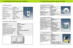
Internet module
Index
Internet Module
1. Introduction
5
2. Simon VOX2 Internet connection equipment
6
2.1 Minimum requirements of the system
3. Installation and setup
4. Operation
4.1 Main Page
7
8
10
11
4.1.1 Menu bar
12
4.1.2 Climate control
12
4.1.3 Intruder alarm
13
4.1.4 IP camera control
15
4.1.5 Technical alarm indicators
15
4.1.6 Configurable service buttons
16
4.2 Setup Screen
17
4.2.1 Menu bar
17
4.2.2 Alarm messages
18
4.2.3 User parameters
19
4.2.4 Network parameters
19
4.2.5 Email parameters
20
4.2.6 IP camera setup
21
4.2.7 Date and time setup
22
5. Technical characteristics
23
6. Recommendations for use
24
7. Troubleshooting
25
APPENDIX 1. ADSL modem configuration
26
APPENDIX 2. Network configuration
30
APPENDIX 3. Configuration of IP addressing for cameras
33
User’s Manual
Internet Module
1. Introduction
The Internet Module is designed to provide an IP (Internet Protocol) residential gateway
interface to SimonVOX.2. Its connection to the SimonVOX.2 system’s main bus RS-485
allows commands to be received and sent to SimonVOX.2, so that from anywhere in the
world it is possible to connect, via internet, to the SimonVOX.2 system and carry out
operations. This is also possible from a home PC.
The SimonVOX.2 internet connection equipment provides a TCP/IP connection to the
SimonVOX.2 domotics system, adding a web interface for displaying and controlling
programmed functions in the home, rapidly, easily, intuitively, securely and remotely.
5
Internet Module
2. Simon VOX2 Internet connection equipment
The package supplied contains the following elements:
z Internet Module
z Installation sheet
6
User’s Manual
User’s Manual
Internet Module
2.1 Minimum requirements of the system
A personal computer with a 2GHz processor or higher, equipped with one of the browsers listed below is needed in order to correctly view the Simon VOX.2-IP website: Microsoft Internet Explorer 6.0 (or higher), Mozilla Firefox 1.0 (or higher) or Opera 8.0 (or
higher).
If Microsoft Internet Explorer is used, the “Software install blocked” option (default)
should be deactivated in the “Tools > Internet Options > Advanced options > Security”.
In order to access the system from within the home, an Ethernet network with the requirements explained in the guidelines should be available. A local network connection via
a network switch or hub is recommendable.
7
User’s Manual
Internet Module
3. Installation and setup
The Internet module has the following inputs and outputs for connection to the SimonVOX.2 mainframe, electricity supply and computer network:
z An halfduplex uninsulated RS-485 communications port (A, B and GND)
z A Fast-Ethernet connection (IEEE 802.3u, 10/100 Base TX)
z Una entrada 230 V~ para alimentación
In order to install the Internet module correctly, the diagram below should be followed in
the installation frame inside the home:
Internet module connection diagram
The RS-485 bus connection board is as follows:
Internet Module
SimonVOX.2
A
A
B
B
GND
Bat-
Copper braid to earth
(both sides of cable)
8
User’s Manual
Internet Module
Safety warnings:
z Keep out of reach of children
z The equipment is connected to the power supply therefore neither the
connection strips nor supply cables should be touched.
z Do not spill liquids on the equipment
z Keep out of direct sunlight.
z As a safety measure that must be complied with and in order for the equipment
to work correctly, it must be earthed.
The recommended cable sections are shown in the following table:
Connection
Terminal
Mains supply
LN
RS-485
A B GND (
)
Minimum Section
Cable Type
(3) 1,50 mm 2
H055RR-F o H05VV-F
(3) 0,55 mm 2
Shielded twisted pair
Unitronic ST3xAWG20/7
The Internet module has two luminous indicators (LEDs):
z Red LED (OK): Electricity supply indicator and of problems with hardware test
or communication with the SimonVOX.2 mainframe.
z Green LED (NETWORK): Ethernet connection status indicator.
The meaning of each of the luminous indicators’ status is described in the following
table:
LED colour
Internet Module Status
Flashing red
The start test has not been successful and there is no connection
with the SimonVOX2 mainframe
Red on
The module is connected and operative
Green on
The module has an Ethernet connection
Green off
The module does not have an Ethernet connection
9
Internet Module
User’s Manual
4. Operation
Once the Internet module is connected to the local network, services offered via the web
interface can be accessed. In order to do this a PC with a local network or Internet connection and with an internet browser installed, is needed.
To access the equipment, open the internet explorer and introduce the following address:
http:// <IP>
<IP> corresponds to the Internet module’s IP address. By default, this is 192.168.3.10.
This address can be modified as explained below.
Once the specified address has been introduced, the following information will appear
on the screen.
The different operations available on the web pages should be carried out one by one
and not before the page has completely downloaded.
To access the system introduce the user name and password, which by default are:
z User: simon
z Password: simon
10
User’s Manual
Internet Module
Subsequently the user name and password can be change (this is recommended), following the steps described below.
Once the user name and password have been introduced, click on the button
will open the “Home Page”.
, which
NB: The “ and & characters cannot be used.
If the incorrect user name and password are introduced 3 times a message will appear
indicating that the limit of attempts has been reached. After 5 minutes a new attempt
may be made.
If a user is already connected, a message will appear indicating this and access will not
be granted until said user has disconnected or the session expires.
4.1 Main Page
The Main Page appears as follows:
Main Page Window
11
User’s Manual
Internet Module
4.1.1 Menu Bar
The menu bar at the top shows information regarding the date (left), current temperature
in the home (centre) and the time (right).
It also displays the following icons:
Refresh: This updates the information on the screen. This command should be
used regularly in order to avoid problems of session timeout.
Setup Screen: This enables access to the Setup Screen.
Disconnect: Once all operations have been carried out this command ends the
session and closes the page.
4.1.2 Climate control
The Climate Control screen allows the preferred temperature inside the building to be
adjusted.
Climate Control Screen
The Climate Control screen carries out the following functions:
Activate/Deactivate Heating: The heating can be switched on and off regardless of the temperature shown on the thermostat. With this command
activated the temperature will always be maintained above the level shown
on the thermostat.
Activate/Deactivate Air Conditioning: The air conditioning can be switched on and off regardless of the temperature shown on the thermostat.
With this command activated the temperature will always be maintained below the level shown on the thermostat.
12
User’s Manual
Internet Module
Activate/Deactivate Thermostat: The thermostat can be switched on or
off using this function. Once the thermostat is activated, the system will
connect or disconnect the heating or air conditioning with the aim of
maintaining the temperature previously set on the Temperature Controller.
Control of the thermostat cannot be validated with the air conditioning and heating switched off.
Temperature Controller: The thermostat can be adjusted to the preferred temperature inside the building. The temperature can be set by pressing the arrows; blue (colder) or red (warmer).
Once the changes have been made, press the
out, or the
button to cancel them.
, button to confirm and carry them
4.1.3 Intruder alarm
The Intruder Alarm screen allows the building alarm to be activated or deactivated.
Intruder Alarm Screen
The padlock symbol indicates whether the alarm is currently activated or deactivated.
The alarm can be switched on or off by introducing the PIN number in the box shown
(the PIN number is the same as the one previously configured in the SimonVOX.2 main.
frame intruder alarm) and clicking on the button
NB: The “ and & characters cannot be used.
13
Internet Module
User’s Manual
The different icons shown on this screen have the following meanings:
Intruder alarm deactivated: This icon appears when the alarm is
deactivated by introducing the PIN code.
Intruder alarm activated: When the alarm is activated (introducing the
PIN code) this icon flashes for a few seconds, indicating that the entry/exit time (allowed for leaving the building once the alarm has been
activated) is being counted down. When the time is up, the icon stops
flashing, indicating that the alarm has been activated.
Intruder detected during entry/exit time: If the alarm is activated and
an intruder is detected in the building during the entry/exit time, this icon
will flash on the screen. If, once the entry/exit time has passed, an intruder is still detected, the alarm will go off.
Intruder alarm: If, with the alarm activated, the presence of a stranger in
the building is confirmed, the alarm will go off and this icon will be shown
on the screen, indicating that an unauthorised person has entered the
house.
Important Note: There is a synchronisation time from the moment in which a status
change is made in the Internet module until the information is updated on the internet
browser screen. This could cause a delay between the moment in which the event occurs and when the information is shown on the screen. The synchronisation time depends on the web page’s refresh time. Therefore, manually refreshing the screen information is recommended in order to have the real current situation available (using the
“refresh” button
).
14
User’s Manual
Internet Module
4.1.4 IP Camera Control
The IP Camera Control screen allows four IP cameras to be operated, should they be
available and connected to the same local network. The screen includes four buttons for
selecting each of the cameras.
The panel has four buttons for selecting each of the cameras.
Pressing one of the camera selection buttons opens a new window that displays the
image being captured by that camera at that moment in time.
4.1.5 Technical Alarm Indicators
The Technical Alarm Indicators screen shows whether any of the alarms corresponding
to smoke, gas, water or medical services have been activated.
Technical Alarm Indicator screen (from left to right: smoke, gas, water and medical alarms).
15
Internet Module
User’s Manual
When one of these alarms is activated, the corresponding indicator changes colour (lighting up) and will begin to flash. The user should therefore carry out the necessary measures to resolve the incident.
In order to validate the alarms and tell the system that the alarm has been noted, press
the button
. By pressing this button all the technical alarms that are activated at that
time will be validated.
4.1.6 Configurable service buttons
The Configurable Service Buttons screen allows the buttons previously configured by the
user as services to be connected or disconnected.
Configurable Services Buttons screen
By pressing either button A or B, the corresponding service switch goes from activated
(yellow coloured button) to deactivated (light blue coloured button).
16
User’s Manual
Internet Module
4.2 Setup Screen
The Setup Screen appears as follows:
Setup Screen
4.2.1 Menu Bar
The menu bar at the top shows information regarding the date (left), current temperature
in the home (centre) and the time (right).
It also displays the following icons:
Main Page Screen: This enables access to the Main Page.
Disconnect: Once all operations have been carried out this command ends the session and closes the page.
17
Internet Module
User’s Manual
4.2.2 Alarm Messages
The Alarm Messages screen allows the personalisation of messages that will be sent to
a specific email address when the corresponding alarm is activated.
Alarm Messages screen (from top to bottom, configuration of messages regarding: Intruder, medical,
water, smoke and gas alarms).
For each of the different alarms a “subject” and “text” can be introduced. These will appear in the email sent in the subject and body text fields of the email. The “subject” and
“text” fields cannot contain more than 50 characters.
Once the “subject” and “text” have been introduced, click on the button
the changes.
to confirm
NB: The “ and & characters cannot be used.
When one of the alarms is activated, a message will automatically be sent previously selected email address warning of said alarm.
18
User’s Manual
Internet Module
4.2.3 User Parameter
The user name and password for accessing the Interent module from the internet
browser can be changed in the User Parameters screen.
User Parameters Setup Screen
To make changes introduce the new user name in the “User” box. Then introduce the
new password in “Password 1” and confirm this new password by reintroducing it in
“Password 2”.
Both the user name and the password should have a minimum of 5 letters and maximum of 11.
NB: The “ and & characters cannot be used.
In order to validate the changes, click on the
Parameters screen.
button at the bottom right of the Email
The next time the system is accessed via the web browser the new user name and password can be used.
4.2.4 Network parameters
The Network Parameters screen allows the IP address used by the Internet module in
the local network, to be modified.
Network Parameters Setup Screen
19
User’s Manual
Internet Module
To make changes introduce the IP address in the “IP” box. Next, fill in the “Port”, “Mask”
and “Connection port” boxes with the corresponding information, according to the local
network configuration.
In case you do not know the IP adress of the external servers, the e-mail server for example, it
is possible to use a domain name. In order to recognise it, introduce Primary DNS and Secondary DNS data as defined by your Internet Service Provider.
In order to validate the changes, click on the
Parameters screen.
button at the bottom right of the Email
NB: The “ and & characters cannot be used.
If any queries should arise with regard the modification of network parameters we recommend that the network administrator be consulted.
4.2.5 Email parameters
In order to send an e-mail you must associate an authentified mail Server so that the Internet Module could send it. This mail server has to support SMTP protocol with LOGIN
and PASSWORD capabilities, supported by most of the mail servers in the market.
The Email Parameters screen allows the email address, to which corresponding warning
messages will be sent when a system alarm is activated, to be modified.
Email Parameters Setup Screen
To make changes introduce the email address to which the messages should be sent
(maximum 50 characters) in the “Email address” box. Next introduce the email server’s
IP address in “Server IP address”. Finally, introduce the email account’s user name and
password, in the “User” and “Password” boxes.
In order to validate the changes, click on the
NB: The “ and & characters cannot be used.
20
button at the bottom right of the screen.
User’s Manual
Internet Module
To check that the email is working correctly click on the
button at the bottom left of
the screen. An email will be sent to the address configured. If the configuration is correct, the test email will be received in the in-box.
If any queries should arise with regard to the modification of email parameters, we recommend that the network or email administrator be contacted.
4.2.6 IP Camera setup
The IP Camera Parameters screen allows the IP address, of up to four IP cameras connected and configured for the local network (where available), to be modified.
IP Camera Setup Screen
* See annex 3 for additional information.
Directly introduce the external ADSL IP address (NOT the internal network address) with
the NAPT port corresponding for each one of the cameras available.
Alter that introduce the internal IP address in the proper “Ruta IP Interna” for each one
of the cameras avalilable.
If any queries should arise with regard to the modification of IP camera parameters we
recommend that the network administrator be contacted.
21
User’s Manual
Internet Module
4.2.7 Date and time setup
The Date and Time Setup screen allows the system’s time and date to be modified.
Date and Time Setup Screen
To modify the date and time simply introduce the values in the corresponding text boxes
and click on the
button to confirm the changes.
The date format is DD/MM/YYYY and the time format is HH:MM:SS.
The automatic synchronisation parameters are only useful when the system has an internet connection, enabling the time and date of the different real time servers found on the
internet to be consulted.
22
User’s Manual
Internet Module
5. Technical characteristics
The Internet module’s technical characteristics are listed in the following table:
Characteristic
Descripción
Item number
81216-39
Mains supply
230 V~ 10% 50/60Hz
Energy cosumption
15 mA
Power supply terminals
(3) 1,5 a 2,5 mm2
RS-485 connection terminals
A, GND, B
Ethernet network
10/100 BaseT (RJ-45) with automatic
crossover detection (auto-crossover)
Led OK
Red (power supply and test)
Led NETWORK
Green (Ethernet connection status)
Working temperature margin
0ºC a 50ºC
Storage temperature margin
-20ºC a 75ºC
Relative humidity
10 a 90% (without condensation)
Certificates
EC
Eletrical safety regulations
EN60950-1
EMC Regulations
EN55022, EN55024, EN61000-3-2,
EN61000-3-3, EN61000-4-2, EN61000-4-3,
EN61000-4-4, EN61000-4-5, EN61000-4-6,
EN61000-4-8, EN61000-4-11
Dimensions
DIN box 4 modules
23
Internet Module
User’s Manual
6. Recommendations for use
In order to correctly use the SimonVOX.2 Internet module, the following considerations
and recommendations for use should be taken into account:
z Contact the network administrator with regard to the technical details of the net-
work configuration before beginning to install the SimonVOX.2 Internet module.
z It is strongly advised that the “refresh” (
) and “disconnect” (
used in order to avoid session maintenance problems.
) buttons be
z The SimonVOX.2 Internet module uses SSL safety protocols. However, precaution
should be taken when accessing the network in locations not normally used or
that could be used by other users. Additionally, passwords should be kept in a
safe place.
24
User’s Manual
Internet Module
7. Troubleshooting
This section aims to provide help with possible problems that could occur in the configuration and installation of the SimonVOX.2 Internet module and how to solve them.
Error
Possible Cause
Solution
No indicators light
The equipment is not
Check the equipment’s power supply
up.
correctly connected
connections and make sure they are
to the power supply.
correctly connected
The Internet module’s
The start test has not
Check the equipment’s RS-485 connections
red LED is flashing.
been successful and
(A, B and GND) and make sure they are
there is no
correctly connected to the SimonVOX.2
connection with the
module.
SimonVOX2
Also check that the SimonVOX.2 module is
mainframe.
working correctly
The Internet module’s
The Internet module
Check the Vox2IP equipment’s Ethernet
green LED is off.
doesn’t have an
connections and make sure the Ethernet is
Ethernet connection.
working correctly
The Internet module’s
The equipment’s
Check the Internet module’s LED indicators
website cannot be
configuration is not
and make sure it is working correctly.
accessed from the
correct.
Check that the IP address introduced in the
computer.
web browser, corresponds with the IP
address and subnetwork mask configured in
the Internet module.
Check that the PC and the Internet module
are connected to the same network.
Check that the PC has the TCP/IP properties
configured correctly.
If the problem cannot be resolved, contact the network administrator.
25
Internet Module
User’s Manual
Appendix 1. ADSL Modem Configuration
For the system to work correctly, the access router should be configured so that the
connection routing for external access is permitted. In order to do this, a NAT (Network
Address Translation) will be carried out on the router, allowing both the allocation of an
access port to the Internet module and the assignation of the specific IP address.
The typical ADSL MODEM configuration (the ZyXEL model has been used as an example) for a domestic network in which a Personal Computer is connected directly to the
ADSL MODEM or a HUB/SWITCH, is described below.
ADSL / ROUTER Modem
Personal Computer
Remote Computer
Public IP
From the Personal Computer we can remotely configure the ADSL MODEM / Router with
the Internet browser.
26
User’s Manual
Internet Module
The ADSL MODEM requests the User Name and Password in order to configure it. This
information can be found in the ADSL MODEM user manual or by contacting the Network Administrator.
On the ADSL MODEM’s main screen:
Click on the NAT option:
27
Internet Module
In this case we click on the Edit Details of the SUA Only option
28
User’s Manual
User’s Manual
Internet Module
Finally, click on “Save” to save the changes and to finish the ADSL MODEM configuration
The 8000 port has now been redirected to the Internet module, allowing the system to
be accessed remotely via the browser address “http://<IP>:8000”
Should the address be placed in the first line (IP Address of line 1) we will have allocated
the address singularly to the Internet module, therefore the access port for remote connections need not be defined. In this case, we can remotely access the system using the
browser address “http://<IP>:8000”.
29
User’s Manual
Internet Module
Appendix 2. Network configuration
If one or more computers on the network are to be connected in order to access the SimonVOX.2 system, each of the computer terminals should be configured. This should be
done according to the operating system.
Below is an example with the WindowsXP operating system.
Sequence of PC configuration windows
1. Select Start, settings and
Control Panel.
2. Select Networks Connections
and Telephone connections.
30
User’s Manual
Internet Module
3. Select Local area connection.
4. Select Internet protocol
properties.
5. Automatically select IP
adress and DNS server
supplied by the Internet
service provider chosen by
the user.
Note: The diagrams shown correspond to the standard Windows operating system. If
the operating system is Windows XP this can be done using the local network configuration wizard, which automates the process.
31
User’s Manual
Internet Module
1. Double click on the My Web Sites on the
desktop.
2. On the left hand of the windows, double click
on the Set up or change your home or small office
network icon.
3. Once the wizard windows has appeared follow
the instructions until the process is finalised.
NB: Should the router be configured to operate as DHCP servers, allocating an IP
address to other terminals on the network (so long as said terminals can support it). The
Internet connection module does not recognise the IP address automatic assignation
DHCP protocol. Therefore this address must be configured manually in the Setup
Screen window, as explained in the corresponding section of the manual. Should the IP
address assignation for the network be carried out using DHCP (regardless of whether
said assignation is made by the PC or a router), the camera or IP cameras that are connected to the network must have the IP via DHCP acquisition option deactivated.
32
User’s Manual
Internet Module
Appendix 3. Configuration of IP addressing for cameras
This appendix describes the configuration of IP addresses so that the end user is able to
remotely access the installation where the cameras are, using the internet module.
In theory the routers should be able to redirect the IP and ports. However there are many
routers on the market that do not offer both features.
The use of the internet module is recommended for installations where a fixed
IP address has been contracted with an operator, to avoid the problems deriving
from installations with dynamic IP.
To access the IP module locally or remotely (Internet), the HTTP Protocol is used
and it communicates via port 80.
Often there are ports used by various devices which offer a web service, such as:
•
•
•
•
IP cameras
Routers
Ethernet hard drives
Etc.
Without NAPT addressing, differentiated access of two devices offered by your webserver via port 80 (http) is not possible.
With NAPT addressing, rules that resolve these conflicts can be created.
Example:
Device
Local IP
External Port
Internal Port
IP Camera 1
192.168.1.11
8001
80
IP Camera 2
192.168.1.12
8002
80
In this example to access device 1 remotely (from Internet), we would write:
http://IP_ROUTER:8001
Using a DNS server for dynamic IP.
To access device 2, we would write: http://IP_ROUTER:8002
Using a DNS server for dynamic IP.
33
User’s Manual
Internet Module
Solution
To solve this problem, the possibility of being able to work with a port other than port 80
has been enabled, in the internet module. This port could be modified by the installation
engineer via the USB port using the installation software and from the actual applet of
the VIT@-IP module.
Therefore, for a router that doesn’t have NAPT the internet module would be configured
in the following way:
Device
Local IP
External Port
IP Camera 1
192.168.1.11
80
Internet Module
192.168.3.10
443
In this example to access device 1 remotely (from Inter net), we would write:
http://IP_ROUTER
Using a DNS server for dynamic IP: http://micasa.dyndns.org
To access the internet module, we would write: https://IP_ROUTER
Using a DNS server for dynamic IP: https://micasa.dyndns.org
Problems of DNS server for dynamics IP
It is common for a user who connects to the Internet from home, to use an IP address.
This address can change when reconnecting. This method of assigning an IP address is
called a dynamic IP address (normally abbreviated to dynamic IP).
Internet sites that by nature need to be permanently connected, generally have a fixed IP
address (the same reduction for fixed IP or static IP is applied), meaning that it doesn’t
change over time. Email, DNS, public FTP servers and web page servers need to have a
fixed or static IP address as this is how they are traced on the network.
Via Internet, computers connect themselves using their respective IP addresses. However, for people it is more convenient to use a different notation that is easier to remember
and use, such as domain names. The translation between one and another is resolved
via the domain name servers, DNS.
34
User’s Manual
Internet Module
Definition of DNS Servers with dynamic IP
There are Internet companies dedicated to dynamic IP DNS solutions: They offer free
redirecting services to sub-domain IPs of a long list of available names, providing individuals with the opportunity of creating an internet server for free with an address such as
“wikipedia.dyndns.com”, which has lead to the “Do It Yourself" culture becoming very
popular. Similar to ZoneEdit, it should be updated via a client on the client’s machine,
such as Eponym.
To configure dynamic IP addresses using these services we recommend that the
telecommunications operator with whom you have contracted the service, be
consulted.
36
35
Diputación, 390-392
08013 Barcelona
Tel. +34 902 109 100
Fax +34 933 440 803
e-mail: [email protected]
Customer technical support:
Tel. +34 902 109 700
Fax +34 933 440 807
e-mail: [email protected]
Showroom
Tel. +34 933 440 853