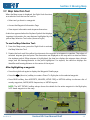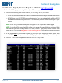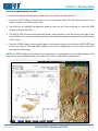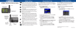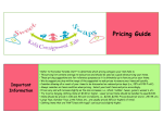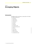
1
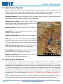
Section 3: Moving Map
3.1 Map Screen Overview
When equipped with a GPS receiver, the HXr provides a moving map screen that is viewable in several
different forms: Full screen, split screen with PFD, engine instruments or approach plate, and
pilot-selectable inset windows. All of the map views have the same basic components:
Aeronatuical features- Airports, airspaces, fixes, and navaids. When zoomed in, runways are displayed
as individual strips with labeled extended runway centerlines.
Topographical features- Cities, towns, major roads,
borders, rivers, lakes, obstacles and terrain. Terrain can be
color coded as a visual proximity warning.
Airplane symbol- Represents your present GPS position
Range/Zoom- All map views use the lower two vertical
softkeys to zoom in and out.
Compass rose/Heading arc- Magnetic compass reference
Path Line- Thin white line represents either present
heading or present ground track, as set in the Moving Map
setup menu, and radiates forward from the airplane symbol.
Flight Plan Course Lines- Magenta is the active leg; all
others are white. See Flight Planning & Navigation.
Heading Bug Course Line- Green course line that appears
when the EFIS is set to navigate in HDG mode.
Weather information-Weather data such as radar and
METARs. ADS-B or XM receiver required.
3.2 Moving Map Database
The moving map is derived from the internal synthetic vision terrain database, the GRT
cities/water/railroads/roads/state boundaries database, and the Navigation Database. The Navigation
Database should be updated every 56 days. A free version is available from the GRT website (continental
U.S. only. Users outside the U.S. must use the Jeppesen subscription-based service.) Both Navigation
Database options display airports, airspace, navaids, fixes, and obstacles on the map. Airport/Facilities
and radio frequency information is also included in the database and is viewable on the EFIS through
the map screen. For more information, see Section 10, Software Updates & Database Maintenance.
NOTE: Databases from external GPS units are not capable of populating the moving map. They can
only transmit GPS position, flight plan data, and autopilot commands across to the EFIS system.
Revision A1
Horizon HXr User Manual Draft
3-1
Section 3: Moving Map
3.3 Map Screen Setup & Customization- Setup Menu
The Map Screen has many options for customization in the Moving Map Setup Menu.
NOTE: To access the Moving Map setup menu, press MORE > Set Menu > Moving Map.
Map Screen Orientation
The map can be set up for Track Up, Heading Up or North Up. To choose the desired orientation:
1. Highlight Up Reference, on top of the Moving Map setup page.
2. Select Track, Heading, or North.
NOTE: This setting affects all map screens, including the Insets. It does not affect the heading tape
on the PFD, which can be set for Track- or Heading-up on the Primary Flight Display Set Menu page.
Airport Symbols and Label Fonts
The airport and font sizes can be enlarged from the default “small” setting. To change font and airport
symbol sizes:
1. Highlight Airport Symbol Size and/or Label Font Size and choose a size option.
Map Screen Declutter Settings
In some areas of the country, there are so many airports, fixes, and navaids that the map gets cluttered
up with information. The HXr has settings to relieve the congestion on the map automatically.
Range Filter- To maintain the readability of the map feature labels, the text size always stays the same
on the screen. As a result, zooming OUT can create an overabundance of information on the map, called
“clutter.” There are several settings in the Moving Map setup menu that allow you to choose which pieces
of information you want to see on the map at certain zoom levels. In general, only the items important
for long-range planning should be displayed on the map at long range.
1. Scroll to the settings for Max or Min Map Range.
2. Choose a distance for each map feature or leave it in the default setting.
3. Select OFF to never display the feature on the map.
Auto Declutter- Automatically remove items from the map in congested areas, starting with small
airports first. To turn on/off:
1. Scroll to Auto Declutter and turn it ON or OFF as desired.
3-2
Horizon HXr User Manual Draft
Revision A1
Section 3: Moving Map
Choose the Default Map Color
While several options for terrain shading and weather are available in the easily-accessible Map Options
softkeys, there are two basic color options that are set up in the Moving Map Set Menu.
Background Color- The backdrop for any screen that does not show topography. It forms the default
background for the radar and METAR screens.
Ÿ Turn Background Color ON to display an even olive green background color for the map. This
creates a neutral background that displays all of the text and features clearly.
Ÿ Turn Background Color OFF to display a black background for the map. Pilots may prefer this
option over the colored background for flying at night.
Color Airports Using METARS- This setting colors the airport symbols of airports with METAR reports
according to VFR, IFR and Marginal VFR flight conditions when there is an operating weather receiver
on board & in data range. See Section 7, Hazard Avoidance, for more information on METARs.
Choose Your Airplane Symbol
The airplane symbol represents your aircraft’s present position and can be customized as a conventional
airplane or a canard. To change the symbol to a canard profile:
2. Press MORE > Set Menu > Moving Map.
3. Scroll to Plane Symbol and select Canard.
Revision A1
Horizon HXr User Manual Draft
3-3
Section 3: Moving Map
3.4 In-Flight Map Setup- “Map Options”
From any Home screen, press SCREEN > Map Options to access the softkeys shown below.
Map Background Options
The SHOW softkey lets the pilot choose one of several mapping data sets to display on the map. This
setting affects all map screens–Full, partial, and inset. See Section 7, Hazard Avoidance, for more
information on viewing weather and terrain warnings. Press SCREEN > Map Options to access the
SHOW softkey choices:
RADAR- Displays ADS-B or XM NEXRAD radar if the aircraft is
equipped with an operable receiver and within range.
SHADE- Displays topography shading similar to that shown on a
VFR Sectional chart. The data is derived from the internal synthetic
vision database. See Map Topography Shading on Page 3-4 for
more information.
TERRAIN- Uses the base SHADE topography and adds yellow and
red coloring as a visual terrain proximity warning.
WIND- Shows winds aloft received by XM Weather. (Not yet functional with ADS-B
as of HXr software release 1g.)
METARS (North-Up map view option only)- Displays airport symbols colored
according to the latest received METAR report and displays a surface wind vector,
ceiling in hundreds of feet, and visibility, as shown at right.
NONE- Displays default map settings as defined in the Moving Map setup menu. Shows basic map
background (either olive or black, as set up in Section 3.3) with no topography shading. Displays
colored airport symbols according to METAR data if the aircraft is equipped with an operational
weather receiver, is within range (ADS-B), and is set up to do so in the Moving Map Setup Menu as
described in Section 3.3.
Compass Rose Display Options
The VIEW softkey lets the pilot choose the presentation of the map compass rose. For more information
on the heading and compass rose presentation on the map screen, see Section 2.6, Heading Indicator.
Press SCREEN > Map Options to access the VIEW compass options:
ARC- Displays the compass rose as an arc in front of the airplane symbol.
CENTER- Displays the compass as a 360° compass rose with the airplane symbol in the center.
NORTH- Displays the map as North UP.
3-4
Horizon HXr User Manual Draft
Revision A1
Section 3: Moving Map
Map Topography Shading
The SHADE option under the SHOW menu colors the map according to the terrain and the Topography
Shading Color Key shown to the right. The base colors are enhanced by shadows in mountainous terrain
to give the map texture and bring attention to the mountain peaks. Elevations are derived from the
internal synthetic vision database.
Elevation in Feet Above Sea Level
0-500
501-2000
2001-3000
3001-5000
5001-7000
7001-9000
Above 9000
3.5 Map Range Controls & Indications
The lower two right-side buttons on the EFIS bezel, labeled RNG, are used to zoom in/out on all map
screens and insets. The map range is displayed:
Ÿ In the upper right corner of the Inset window
In the upper left corner of the full and split map screen views.
Upper portion of split-screen map shown.
Revision A1
Horizon HXr User Manual Draft
Map Inset Window
3-5
Section 3: Moving Map
3.6 Path Line
The Path Line is the fine white line between the Airplane Symbol and
the heading/track readout (Up Reference as set in the Moving Map
set menu). If the map orientation is set to Track Up, this line is a
visual indicator of the map features to be crossed if the present
ground track remains the same. In Heading Up mode, this line has
less value because the path is affected by crosswinds.
When the path line crosses over an airspace boundary and the
altitude of the aircraft falls within the airspace upper and lower limits,
the airspace boundary line turns yellow, as shown at right, or flashes
bright red in the case of prohibited areas. In this screenshot, the
Heading Bug course line (bright green) points off to the 10 o’clock
position, but the aircraft is not following the desired heading. The
path line crosses into the airspace, warning the pilot that the airspace
will be penetrated if the current ground track stays the same.
3.7 Airspace
The GRT map database contains information for all the airspace in
the U.S. including lateral and altitude boundaries, controller
frequencies, and times of operation. Use the Map Selection Tool
and Waypoint Details page to access information about different
airspaces along your route.
Airspace Boundaries- Airspace boundaries are colored according to the U.S. VFR Sectional Chart with
the exception of restricted areas, which are bright red for visibility.
3-6
Horizon HXr User Manual Draft
Revision A1
Section 3: Moving Map
Airspace Labels- When the aircraft’s projected path crosses an airspace
boundary, the airspace is highlighted and the airspace dimensions
appear next to it. This feature also considers altitude– Airspace projected
to pass below or above the aircraft is not highlighted.
In the screenshot at the right, the boundary of the Class D airport is
yellow because the aircraft is on course to enter it. The dimensions of
the airspace are noted inside the airspace boundary ring at the 2 O’clock
position:
NOTE: Labels and dimensions for airspaces that are not in the path of
the aircraft are not displayed on the map for a cleaner, decluttered
presentation.
3.8 Map Symbology
Symbols on the map other than airports and airspace are depicted as the following:
NOTE: U.S. state boundaries are thin white lines.
Navigation
VOR
Railroad
VOR/DME
Major road
VORTAC
Populated place (city or town)
NDB
Body of Water (irregular shapes)
Fix
Revision A1
Map Features
Man-made obstacle. Color corresponds
to Terrain warning (black, yellow or red)
Horizon HXr User Manual Draft
3-7
Section 3: Moving Map
Airports & Runways
Airport symbols resemble those found on VFR sectional charts, but they automatically adapt to the
selected map range and declutter options.
Public airports are depicted as a tan circle icon when the map
range is greater than 10 miles. At or below 20-mile range, a
white stripe is added that shows the orientation of the longest
runway at the airport (See WI67, below right). At a range of
10 miles or less, each runway is displayed in the detailed view.
Runways are shown with blue borders in their magnetic
orientation. Hard surface runways are white and turf or soft
runways are green. The nearest airport detailed view also
features runway identifier labels, as shown in the large image of KHXF at right.
Private airports are depicted in the same way as public airports, except with an "R" inside
the circle symbol, as shown in the examples at right. Note the runway orientation stripe
of WI67, shown here at a map range of 20 miles or less.
The detailed view is only available if at least one runway at the airport has coordinates in
the navigation database. Otherwise, the circle icon for that airport is always shown. Private
airports often don't have actual runway coordinates in the database; therefore, the detailed
view may not be available for private airports. Runway coordinates can be added to the database manually;
See Section — of this manual.
Destination Airport
Runway
Label
If an airport is the last waypoint in the flight plan, it is treated
as the “destination airport.” Extended centerlines are shown
for the destination airport at or below 20 miles of map range
to make it easier to locate the final approach path for the
intended runway. The perpendicular mark on each extended
centerline is placed 1 mile from the end of the runway.
Runway labels are always shown for the destination airport,
even if it is not the nearest airport.
1-mile final
marker
GPS
course
In the screenshot to the right, we see the aircraft turning
onto final approach for a clearly-labeled Runway 36 in
Oshkosh, WI (KOSH). Oshkosh has multiple runways, the
centerlines of which are all displayed on this map. The
magenta line is the original GPS flight plan, tracking to the
center of the airport. The green line radiating eastward from
the airplane symbol represents the heading bug, which was
set up for a left base for Runway 36.
3-8
Horizon HXr User Manual Draft
Runway
Extended
Centerline
Heading Bug
course
Revision A1
Section 3: Moving Map
3.9 Map Selection Tool
When the Map screen is displayed, the Right Knob functions
as a selection tool that can be used to:
Ÿ Select and go direct to a waypoint
Ÿ Access the Waypoint Information Page
Ÿ View airport information and airspace dimensions
A data box appears below the Airplane Symbol that displays
important information for map features highlighted by the
yellow Map Selection Tool cursor (shown at right).
To use the Map Selection Tool:
1. From the Map screen, press the Right Knob to activate
the Map Selection Tool.
2. Rotate the knob until the yellow line intersects the waypoint or airspace in question. The edges of
selected airspace glow turquoise. The dimensions are displayed on the map and in a data box below
the airplane symbol. When airspace is highlighted, the data box displays the airspace class, altitude
range, and the bearing/distance to the point highlighted. For airports, the data box displays the
identifier and bearing/distance to the center of the airport.
After highlighting a waypoint:
Ÿ Press the right knob again to display the Waypoint Details page.
Ÿ Press the
(direct-to) softkey to create a Direct-To flight plan to the selected waypoint.
Ÿ Press NEAR softkey, then AIRPORTS, NAVAIDS, WTHR FREQ or METARs softkey to choose a list of
nearby waypoints, AWOS/ASOS frequencies, or METAR reports.
NOTE: The WPT DETAILS softkey always shows the details for the active waypoint in the flight plan,
NOT theed waypoint on the map.
Revision A1
Horizon HXr User Manual Draft
3-9
Section 3: Moving Map
3.10 Waypoint Details Page
The Waypoint Details or Airport Facilities Directory page can be accessed several different ways:
a. Through the Map screen using the Map Selection Tool; Highlight a waypoint, then press right knob.
b. Through a Flight Plan page by highlighting an airport or NAVAID and pressing the Right Knob.
c. View details of active GPS waypoint by pressing WPT DETAILS softkey on the Map screen.
Runway
Info
Press FREQ to access radio
tuning softkeys, SET COM or
SET NAV.
These display a scrollable list of
frequencies for the airport.
Press Right Knob to send the
frequency to a remotelymounted radio or panelmounted radio with serial
input from the display unit
(such as Garmin SL30/SL40).
3-10
Press PLATE to load
approach plates for the
airport, if stored in the
system. See GRT
Avionics website for
more information on
how to load approach
plates into HXr.
TAF displays the Terminal
Aerodrome Forecast if
available. (Only if receiving
current weather from an
installed ADS-B or XM
receiver.) Note that METAR
information shows up in the
body of the Details page.
Horizon HXr User Manual Draft
Revision A1
Section 3: Moving Map
3.11 Nearest Airport, Weather Report or NAVAID:
1. From the MAP page, press the Right Knob. (From PFD screen, press FLT PLAN softkey.)
2. Press the NEAR softkey, then choose AIRPORT, WTHR FREQ, METAR, or NAVAID.
Ÿ WTHR FREQ includes nearest AWOS and ASOS weather frequencies that you can select and monitor.
Ÿ METAR shows a list of METARS from nearby airports if you are equipped with an XM or ADS-B
weather receiver and receiving information. This is extremely useful if weather is closing in on your
location.
NOTE: WTHR FREQ and METAR softkeys do not appear on the Flight Plan’s Nearest pages.
NOTE: On the Flight Plan page, the NEAR softkey only appears if you are following an internal flight
plan because flight plans utilizing external GPS units (“external” flight plans) cannot be edited from
within the GRT EFIS unit. See Navigation & Flight Planning section of this manual for more information.
3. In the example below, AIRPORT was chosen. Turn the Right Knob to highlight desired airport, then
press GO TO or
softkey to create a Direct-To flight plan with the selected airport as the waypoint.
4. Press EXIT to exit Flight Plan page and return to the PFD or Map screen.
Revision A1
Horizon HXr User Manual Draft
3-11
Section 3: Moving Map
3.12 Panning the Map
To view objects and waypoints outside of the map viewing area, you can slew, or pan, the map.
1. Press SCREEN > Map Options > SLEW. Four arrow softkeys appear, along with BACK, which navigates
back to the Map Options softkey set, and HOME, which exits the SLEW view.
2. The SLEW map view is always in North-Up mode. Press the arrow softkeys to pan the map north, south,
east or west. The map range/zoom keys and Map Selection Tool work just as they would on the HOME
map screen.
3.13 Traffic Display
The HXr map screen displays traffic targets if the aircraft is equipped to receive either TIS or ADS-B
traffic information.
See Section 7, Hazard Avoidance, for more information on viewing, interpreting and configuring traffic
alerts.
3.14 Displaying Approach Plates
The Map/Chart split screen view allows you to display a PDF approach plate on the left half of one of
the display units. This feature is designed for multi-screen installations, with the chart and map displayed
on a multi-function display. See Appendix of this manual for complete instructions on downloading,
saving and accessing free, up-to-date NACO approach plates on the HXr.
3-12
Horizon HXr User Manual Draft
Revision A1
Section 3: Moving Map
To view an approach plate on HXr:
1. Access the Waypoint Details page of the airport you will fly the approach into.
2. Press the PLATE softkey. This will bring up a list of approach plate PDF files that are stored in the
airport’s folder on the USB thumb drive.
3. Use the knob to highlight the approach plate you want to see. Press the knob or press the VIEW
softkey to display the plate.
4. The MAP/CHART screen will automatically appear, with the plate on the left and moving map on the
right. Softkeys for zooming, scrolling, panning, and rotating the plate are displayed along the bottom
of the screen.
5. Press the HOME softkey to bring up the regular home screen softkeys; note that the MAP/CHART split
screen view stays up. Press left INSET softkey at any time to display the zoom and scroll controls for
the approach plate again.
NOTE: The MAP/CHART view functions as a Home screen. To switch back to primary flight display or full
map screen, press SCREEN softkey, then select PFD, MAP, or MAP/ENG as appropriate.
Revision A1
Horizon HXr User Manual Draft
3-13