1
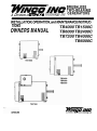
A Div~sionof
BRUSHLESS
TWO-BEARING
Technology Znc GENERATORS
INSTALLATION, OPERATION,and MAINTENANCE INSTRUCTIONS
OWNERS MANUAL
-
A Division of -Dy&
-
-
Techno/oogyfnc
Read and understand all instructions in the manual
before starting and operating the generator set.
USING THIS MANUAL
Congratulations on your choice of a Wnco generator
set. You have selected a high-quality, precision-engineered generator set designed and tested to give you
years of satisfactory portable service.
To get the best performance from your new engine
generator set, it is important that you carefully read and
follow the operating instructions in this manual.
Should you experience a problem please follow the
"Things To Check" near the end of this manual. The
warranty listed in this manual describes what you can
expect from WlNCO should you need service assistance
in the future.
TABLE OF CONTENTS
INTRODUCTION
12 MONTH WARRANTY
GUIDETOPRODUCTSAFETY
BASIC INFORMATION
Specification Table
Unit Capabilities
Unpacking the unit
lNSTALLATIONlOPERATlON
Assembly
Plan The Installation
Connecting The Load
Common Problems
PROPER USE AND INSTALLATION
You must be sure your new generator set is:
* Properly serviced before starting
* Wired by a qualified electrician
* Operated only for its designed purposes
* Used only by operators who understand its operation
Properly maintained
COPY YOUR MODEL AND SERIAL
NUMBER HERE
No other WlNCO generator has the same serial number as
yours. It is importantthat you recordthe number and other vital
information here. If you should ever need to contact us on this
unit it will help us to respond to your needs faster.
MODEL
SERIAL NUMBER
i
i
1
PURCHASE DATE
DEALER
WINCO, Inc. 12 Month Limited Warranty
WINCO, Incorporated warrants to the original purchaser for 12 months that goods manufactured or supplied by it will
be free from defects in workmanship and material, provided such goods are installed, operated and maintained in
accordance with Winco written instructions.
WINCO's sole liability, and Purchaser's sole remedy fora failure under this warranty, shall be limited to the repairof the
product. At WINCO's option, material found to be defective in material or workmanship under normal use andservice
will be repaired or replaced. For warranty service, return the product within 12 months from the date of purchase,
transportation charges prepaid, to your nearest WlNCO Authorized Service Center or to WINCO, Inc. at Le Center
Minnesota.
THERE IS NO OTHER EXPRESS WARRANTY.
To the extent permitted by law, any and all warranties, including those of merchantability and fitness for a particular
purpose, are limited to 12 months from date of purchase. In no event is WINCO liable for incidental or consequential
damages.
Note: Somestates do notallowlimitation on the duration ofimplied warrantyandsomestates do notallowthe exclusion
or limitation of incidental or consequential damages, so the above limitations may not apply in every instance. This
warranty gives you specific legal rights which may vary from state to state.
WlNCOreserves the right to change or improve its products without incurring any obligations to make such changes
or improvement on products purchased previously.
EXCLUSIONS:
WlNCO does not warrant engines, batteries, or other component parts that are warranted by their respective
manufacturers.
WlNCO does not warrant modifications or alterations which were not made by WINCO, Inc.
GUIDE TO PRODUCT SAFETY
L
This engine generator set has been designed and manufactured to allow safe, reliable performance. Poor maintenance, improper or careless use can result in potential
deadly hazards; from electricalshock, exhaust gas asphyxiation, or fire. Please read all safety instructions carefully
before installationor use. Keep these instructions handy for
future reference. Take special note and follow all warnings
on the unit labels and in the manuals.
ANSI SAFETY DEFINITIONS
DANGER:
DANGER indicates an imminently hazardous situation which, if not avoided, will
result in death w serious injury. This
signal word i s to be limited to the most
extreme situations.
WARNING:
WARNING indicates a potentially hazardoussituation which, ifnotavoided, could
result in death o r serious injury.
CAUTION:
CAUTIONindicatesapotentiallyhazardous
situation which, if n o t avoided, may result inminor o r moderate injury. I t may
also b e used to alert against unsafe
practices.
NOTE:
CAUTIONisalso usedon the unitlabels and
inthismanualto indicate a situation that
could result in serious damage o r destruction o f the equipmentandpossible
personalinjury.
2. FIREHAZARD-Gasolineand otherfuelsalways present
a hazard of possible explosion andlor fire.
a. Do not refuel when the engine is running or hot. Allow
the engine to cool at least two minutes before refueling.
b. Keep fuel containers out of reach of children.
c. Do not smoke or use open flame near the generator set
or fuel tank.
d. Keep a fire extinguisher nearby and know its proper
use. Fire extinguishers rated ABC by NFPA are appropriate.
e. Store fuel only in an approved container, and only in a
well-ventilated area.
3. DEADLY EXHAUSTGAS -Exhaustfumesfrom any gasoline enginecontain carbon monoxide, an invisible, odorless and deadly gas that must be mixed with fresh air.
a. Operate only in well ventilated areas.
b. Never operate indoors.
c. Never operate the unit in such a way as to allow exhaust
gases to seep back into closed rooms (i.e. through
windows, walls or floors).
-
4. NOISE HAZARD Excessive noise is not only tiring, but
continual exposure can lead t o loss of hearing.
a.Use hearing protection equipment when working
around this equipment for long periods of time.
b. Keep your neighbors in mind when permanently installing this equipment.
5. CLEANLINESS- Keep the generator and surrounding
area clean.
a. Remove all grease, ice, snow or materials that create
slippery conditions around the unit.
b. Remove any rags or other material that could create
potential fire hazards.
c. Carefully wipe up any gas or oil spills before starting the
unit.
d. Never allow leaves or other flammable material to build
up around the engine exhaust area.
6. SERVICING EQUIPMENT-All service, including the installation or replacement of service parts, should be
performed only by a qualified technician.
a. Use only factory approved repair parts.
b. Do not work on this equipment when fatigued.
c. All belts, pullies andlor drive shafts must have protective guards andlor covers permanently installed by the
assembler.
d. Never remove the protective guards, cover, or receptacle panels while the engine is running.
e. Use extreme caution when working on electrical components. High output voltages from this equipment can
cause serious injury or death.
f. Always avoid hot mufflers, exhaust manifolds, and
engine parts. They all can cause severe burns instantly.
1. ELECTRICSHOCK- The output voltage present in this
equipmentcan causeafatalelectric shock. Thisequipment must be operated by a responsible person.
L
a. Do not allow anyone to operate the generator without
proper instruction.
b. Guard against electric shock.
c. Avoid contact with live terminals or receptacles.
d. Use extreme care if operating this unit in rain or snow.
e. Use only three-prong grounded receptacles and extension cords.
f. Be sure the unit is properly grounded to an external
ground rod driven into the earth.
Page 1
TB
SERIES
BASIC INFORMATION
TESTING POLICY:
CONVENTIONAL D U A L VOLTAGE
1 2 0 / 2 4 0 VOLT SCHEMATIC
Before any generator is shipped from the factory, it is
fully checked for performance. The generator is
loaded to its full capacity, and the voltage, current, and
frequency are carefully checked.
Rated output of generators is based on factory tests of
typical units, and is subject to, and limited by the
ambient operating temperature. The generator will
not provide full power output unless driven by a prime
mover of adequate horsepower. The prime mover
(engine or other input power source) horsepower is
also affected by temperature as well as a number of
other factors such as: fuel, altitude, and all other
conditions specified by the prime mover manufacturer.
Neutral
E
--
-
A A
120 Volts
G r o ~ n d ~r\k ' 2 $ o c l e s
INTRODUCTION AND DESCRIPTION
TYPICAL 4000 WATT GENERATOR
The generator is a 3600 rpm two bearing, belt driven,
brushless, revolving field design. The generator is self
excited and inherently regulated to +(plus
I- or minus)
7% - no load to full rated load. It can be operated
under any load within its rating without being damaged. The frequency regulation is determined by the
sensitivity of the customer supplied prime movers'
governor. It is desirable to maintain this speed to
within 3 cycles variation (61.5 Hz 58.5 Hz) no load to
full rated load (3690 rpm - 3510 rprn).
The following currents (measured in amps) are produced at
120 & 240 volts for typical wattage shown.
AMPS AT
120 VOLT
240 VOLT
RECEPTACLE ID
MODEL
A
C
B
TB1500C
12.5
NIA
NIA
TB2400C
20
NIA
NIA
TB4000C
16.7
16.7
16.7
TB4000*
16.7
16.7
16.7
TB6000C
25
25
25
TB6000*
25
25
25
TB7200**
30
30
30
'Customer connections are made on the back side
of the circuit breaker
-
Generator Specifications
MODEL
WATS
VOLTS
AMPS
HZ
PH
RPM
** This unit has a junction box rather than receptacles. Ref. "amisthe G I lead, Ref. "c" is the G3 lead
and Ref. "b" is G I to G3 rating
UNIT CAPABILITIES
1. Generator Coni-lections- The diagram below represents
a typical ordinary 4000 watt generator. Only 2000 watts at
120 volts (16.7 Amps) can be taken from the generator at
receptacle A and up to 2000 watts at 120 volts from
receptacle C. On an ordinary generator, CAUTION MUST
BE EXERCISEDTO PREVENTOVERLOADINGEITHER
OF THE 120 VOLT CIRCUITS (A OR C).
TB SERIES
2. Starting Electric Motors - Electric motors require much
more current (amps) to start them than to run them. Some
motors, particularly low cost split-phase motors, are very
hard to start and require 5 to 7 times as much current to start
them as to run them. Capacitor motors are easier to start
and usually require 2 to 4 times as much current to start
them as to run them. Repulsion Induction motors are the
easiest to start and usually require 1-112 to 2-112 times as
much to start them as to run them.
Page 2
Most fractional horsepower motors take about the same
amount of current to run them whether they are of Repulsion-Induction (RI), Capacitor (Cap), or Split-Phase (SP)
type. The chart below shows the approximate current
required to start and run various types of sizes of 120 volt
60 cycle electric motors under average load conditions.
60706-098
-
BASIC INFORMATION
-
HP
116
114
113
112
1
RUNNING
AMPS
3.2
4.5
5.2
7.2
13.0
SP
1 6 T 0 22
22TO32
26TO35
NOTMADE
NOTMADE
STARING AMPS
CAP
RI
6 TO13 S T 0 8
9T018 7T012
1 0 T 0 2 18T017
14TO2911TO18
26 TO 52 20 TO 33
The figures given above are for average load such as a
blower or fan. If the electric motor is connected to a hard
starting load such as an air compressor, it will require
more starting current. If it is connected to a light load, or
no load such as a power saw, it will require less starting
current. The exact requirement will also vary with the
brand or design of the motor.
For 240 volt motors, the "running" current is half as much
as shown for the 120 volt motors of the same size. Some
dual voltage 1201240 volt motors are difficult to start on
240 volts when driven by enginelgenerators and can be
started more easily when connected to operate on 120
volts. This is particularly true of "capacitor start-induction
run" motors. Sometimes a 240 volt motor which cannot
be started on the 240 volt circuitof a 1201240voltgenerator
can be started on a 120 volt circuit and then auicklv
switched to the 240 volt circuit after it is started. c his c a i
be done in applications where the motor is manually
controlled and is started under "no load" conditions.
-,
Generator
Model
Trying to start a larger motor or higher code (ie. J or K)
motor may result in damage to boththe generatorand the
electric motor especially 120 volt motors.
UNPACKING INSTRUCTIONS
** NOTICE **
When unpacking the generator, be sure to inspect it
carefully for freight loss or damage. If loss or damage
is noted at the time of delivery, require that the person
making the delivery make a note of the loss or damage
on the freight bill, or affix his signature under the
consigner's memo of the loss or damage. Contact the
carrier for claim procedures.
When loss or damage is noted after delivery, segregate the damaged material, and contact the carrier for
claim procedures.
A self-excited generator responds differently to severe
overloading than the power line. To illustrate, suppose
that a 240 volt 10 H.P. "capacitor start-Induction Run"
motor is connected to the generator. The engine would
not be able to supply enough power to bring the electric
motor up to operating speed. The generator would respond with high initial starting current, but the engine
would be very severely overloaded. The speed would
probably drop sharply and possibly stall the engine. If
allowed to operate at very low speeds, the electric motor
startwinding would burn out in a shorttime. The generator
winding might also be damaged.
"CONCEALED DAMAGE" is understood to mean
damage to the contents of a package which is not in
evidence at the time of delivery by the carrier, but which
is discovered later. The carrier or carriers are responsible for merchandise lost or damaged in transit. The
title to goods rests with the consignee when generators are shipped fob factory, and only the consignee
can legally file claims.
1. Carefully open carton.
2. After inspecting the generator for external physical
damage, check for the owner's manual (operating
instructions, wiring diagram, parts list) inside the
carton.
On the other hand, suppose a smaller electric motor that
requires just a little more output than the generator can
produce is connected to it. It will try to run but will not reach
a high enough speed for the internal centrifugal switch to
disconnect the starting winding. The generator output,
instead of being 120 volts, may drop to 70 or 80 volts.
RUNNING THE GENERATOR SET UNDER EITHER OF THESE CONDITIONS
COULD RESULT IN DAMAGE TO THE
GENERATORSTATORASWELLAS THE
MOTOR WINDING.
L
Because the heavy surge of current required for starting
motors is required for only an instant, the generator will
not be damaged if it can bring the motor up to speed in a
few seconds of time. If difficulty is experienced in starting
motors, turn all other electrical loads off and if possible
reduce the load on the electric motor.
3. Motor Starting Ca~acitv- listed below vou will find the
motor starting ~>~al;ilit~
bf your engine ienerator set.
60706-098
Motor Size
(code "G"capacitor start)
2. Remove generator hold down bolts.
4. Unit can now be lifted from shipping base.
**** CAUTION ****
Before proceeding with the installation, be sure that you
have completely read and understand the assembly
and installation instructions.
ASSEMBLY
1. An engine with adequate horsepower and a close
regulating (fixed speed) governor is required for
satisfactory operation of any alternating current
generator.
Page 3
TB
SERIES
INSTALLATION
These units require approximately two (2) horsepower
for every 1000 watts of generator output. Theoretically
you should be able to produce 1000 watts with 1.4
Horsepower, but this is only possible with 100%
efficiencies in both the engine and the generator.
Between engine and generator efficiencies of only 80%
to 90% and the losses through the drive system the two
horsepower requirement is more realistic.
together with the natural "voltage drop" within the
generator itself due to load current and heating of the
windings, results in a slightly lower voltage than when
the generator is running idle.
The normal, slight variations in speed also directly affect
the frequency of the output current. This frequency
variation has no appreciable effect in the operation of
most loads (such as motors, lights and most small
appliances). However, timing devices and clocks will
not keep perfect time unless the engine can keep the
generator running at exactly 3600 rpm at all times.
Since this is not usually possible, minor time errors in
clocks occur.
For example, this 1,500 watt generator output will
require a 3 or 4 h.p. Engine for full output, good speed I
voltage regulation, and satisfactory load performance.
2. When determining the prime mover Igenerator pulley
ratio to drive the generator at the correct operating
speed, bear in mind that the power rating of most prime
movers (usually an engine) varies with the speed-that
is, it produces more power at higher speeds, less when
slowed. The prime mover must be run fast enough to
reach the desired horsepower for good generator set
operation.
The speed of the engine is usually adjusted so that the
generator produces proper voltage. If the adjustment is
made "cold", set the voltage a little higher than normal
since it will drop a few volts as the generator warms up.
**" CAUTION ****
When operating continuously at full load the generator
shell becomes very warm. It will be uncomfortable to
the touch-this is normal for any high performance
inherently regulated generator.
The drive belt system must be of adequate size and
must be tight enough to power the generator without
slippage. Be careful not to overtighten to the extent that
it puts excessive strain on the bearings--doing so can
cause bearing failure and other possible damage to the
generator.
Output voltage should be checked periodically to
insure proper operation of the generating plant and
appliances.
Alignment of the generator to the prime mover is
important. Misalignment of the pullies will cause
excessive belt and pulley wear and unnecessary stress
on the prime mover.
**** CAUTION "**
Although individual units and models may vary slightly,
the normal voltage and frequency of typical 60 cycle
generators described in this book are approximately as
follows when powered by a typical prime mover (engine)
run first with no load applied, then at half the generator
capacity and finally when loaded to its full capacity as
rated on the nameplate:
Required generator speed must be maintained at 3600
+I- 90 rpm under all load conditions.
4.All engines have a tendency to slow down when a load
is applied. The governor on the engine is designed to
hold the engine speed nearly constant. When the
electrical load connected to the generator is increased,
the engine is more heavily loaded and as a result the
speed drops slightly. This slight decrease in speed
TB SERIES
PLAN THE INSTALLATION
Plans for installation should be prepared with proper
attention to mechanical and electrical engineering detail
to assure a satisfactory system installation. The
information in this manual is offered as a guide to
finalizing your installation plans. The installation
sequence is summarized below:
VOLTAGE
129VOLTS
120VOLTS
115VOLTS
**** CAUTION ****
-
Low voltage may damage any motors or appliances
connected to it. Running the generator at excessively
high speeds results in too high voltage which will also
damage electrical devices connected to it. Excessively
high speed may also cause damage to the generator
stator windings.
3. The following table shows the effect of various operating
speeds and electrical loads on a typical generator when
matched and mounted to an adequate prime mover
GENERATOR
LOAD
SPEED FREQUENCY
NONE 3690 RPM
61 112 HZ
HALF 3600RPM
60HZ
FULL 3510 RPM
58 112 HZ
--
Generally these two bearing generators are used on
portable equipment. For best service consider the
following :
1.All electrical equipment should be protected from
excessive moisture. Failure to do so will result in
deterioration of the insulation and will result in short
circuits and grounds.
2. The generator should be installed in a sheltered area. If
the unit must be left in the open, it should always be
protected with a weather cover such as a tarp or large
piece of canvas after each use to keep out water and
dust.
P'age 4
60706-098
-
BASIC OPERATION
-
"*
CAUTION ****
pump and other
items to be powered directly into
the generator receptacles. Before
plugging in all
the tools and cord sets, recheck the rating of the
generator set. Be sure it can handle the intended load
and is compatible with the voltage, phase, and current
ratings.
Always allow the generator and prime mover to cool
before covering with a flammable weather covering.
**** CAUTION *"*
The generator must be mounted with the engine to a
common rigid base to prevent stress on the engine
and generator shafts and bearings due to
vibration displacement. For permanent installations,
the engine-generator is usually mounted on a subframe which can be shock mounted with special
neoprene pads on the main frame.
f. 'Hard Wiring' this unit directly into a temporary construction site electrical system is NOT A SIMPLE DO-ITYOURSELF JOB. For your safety all wiring must be
done by a qualified electrician and conform to the
National Electric Code and comply with all state and
local codes and regulations. Check with local authorities before proceeding.
CONNECTING THE LOADS
****WARNING""
1. Applying The Load - A shortwarm-up time will permitthe
engine to work more efficiently when the load is applied
and will reduce the wear and extend its life.
a. Rece~tacleshave been Drovided on the control Dane1
tocohect the loads on the models, TBI ~ O O C
T,B ~ ~ O O C ,
TB4000C, TB6000C. On the models TB2400, TB4000,
TB6000 the connections are made on the back side of
the circuit breakers. The TB7200 has a junction box
mounted on the top of the generator. The loads should
be applied gradually. If a large motor is being started
or multiple motors are being started, they should be
started individually and the largest should be started
first.
L
**" CAUTION ****
PERSONAL DANGER A fully isolated, double pole
double throw manual transfer switch must be installed
any time a generator is being connected to an existing
distribution system.
**"CAUTION"*
COMMON PROBLEMS
EQUIPMENTOVERLOAD-Keepthe generator loadwithin
the generator and receptacle nameplate rating. Overloading may cause damage to the generator andlor the
loads
b. Most electric tools and appliances will have the voltage
and amperage requirements on their individual nameplates. When in doubt consult the manufacturer or a
local electrician. The nameplate amperage rating for
electric motors can be misleading. See "Starting Electric Motors" in Specification Section.
-
EQUIPMENT DAMAGE Failure to properly limit and balance the load applied to the generator will cause the
generator to produce low voltage and may damage the
engine generator set. It may also cause severe damage
to the loads connected to the generator at that time.
Improper loading of the generator set constitutes abuse
and will not be covered by warranty.
Sometimes problems can be easily solved by checking
a few basic things. Check below before you call or take
your unit to a service center. It could save you time and
money.
Voltage too low
c. These engine generator sets are inherently self regulating based on engine speed. The engine governor
will automatically adjust itself to the load. No harm to
the generator will result if it is operated with no load
connected.
*Engine speed is too low.
*Generator overloaded.
*Defective stator.
*Defective rotor (field).
Circuit Breaker Trips
'Defective load.
*Defective receptacle.
Voltagetoo high
*Engine speed is too high.
Generatoroverheating *Overloaded.
*Insufficient ventilation.
d. Proper. utilization amperage is necessary to prevent
damage to either the receptacleslbreakers or the generator. The generator is a limited source of electrical
power, therefore pay special attention to the receptacle
and generator ratings. The nameplate rating can be
obtained through a combination of receptacles or a
single receptacle as long as the receptacle amperage
rating is not exceeded. Both the 120 and 240volt output
can be utilized at the same time. See Specification
Section for proper load separation.
Nooutputvoltage
*Short in load (disconnect).
*Broken or loose wire.
*Defective receptacle.
*Defective capacitor.
*Defective diode.
*No residual magnetism in
generator.
*Defective stator.
"Defective rotor (field).
e. Plug your tools such as drills, saws, blowers, sump
60706-098
Page 5
TB
SERIES
WIRING DIAGRAMS
EXCl TATlON
WINDING
(STATOR)
CIRCUIT
BREAKERS
A.C. OUTPUT
WINDING
(STATOR)
UNMARKED LEADS
1
EXCITATION
FIELD
COILS
(ROTOR)
RECTIFIERS
EXClTATlON WINDING
7*--
CIRCUIT BREAKER RECEPTACLES
CAPACITOR
UNMARKED
LEADS
RECTIFIERS
COILS
(ROTOR)
CIRCUIT BREAKER
w
d
EXCITATION WINDING
,rn
f
A.C. OUTPUT
WlNDlNG
120
VOLTS
UNMARKED
LEADS
EXCITATION
RECTIFIERS
COILS
(ROTOR)
A Division of DTLD p Techno/ogyfnc
225 South CordovaAvenue
Le Center, Minnesota 56057
kr_,
vOrl
VOLTS
120
BREAKER
1