1
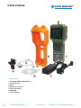
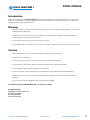
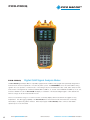
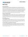
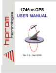
PICO MACOM
PICO-PRO/Q
Digital QAM Signal Analysis Meter
PICO-PRO/Q Owners Manual
Read this manual thoroughly.
Please keep this manual handy for future reference.
Visit our website www.picomacom.com
Contact Us 858.546.5050
Toll Free 800.421.6511
PICO-PRO/Q
PICO MACOM
2
1
5
4
3
6
7
Accessories
1. Instrument (PICO-PRO/Q Meter)
2. Protection Case
3. Strap
4. External F Connector
5. Serial Data Cable
6. RS232 CD
7. Power Adapter
2
www.picomacom.com
Owners Manual
CONTACT US TOLL FREE 800-421-6511
PICO-PRO/Q
PICO MACOM
Introduction
Thank you for purchasing the PICO-PRO/Q Digital Signal Level Meter. We are sure that with proper use and care you
will be very satisfied with your new test equipment. To ensure safe operation of this instrument, be sure to follow the
warnings and precautions provided below.
Warning
• Do not use, place or store the meter where it may be exposed to rain, moisture or high humidity, as moisture can
damage internal components.
• Do not place or store meter where it may be exposed to continuous direct sunlight, as this may damage the
display, keypad, casing or internal components.
• Do not expose the meter in an environment of excessive heat.
• Do not drop, bump, cause impact or use the meter in a rough or careless manner, as this may void your warranty.
Caution
• When operating this meter, use caution if voltage is present on the cable under test.
• This product is not waterproof.
• Do not connect this meter to any circuit that exceeds the maximum power rating.
• To avoid shock or electrocution, always ensure the circuit under test is properly grounded.
• Do not attempt to repair, modify or change the meter battery.
• Do not use a battery charger other than the one provided for charging the internal rechargeable battery.
• Opening the case for any reason will void your warranty and could cause an electrical shock or equipment
damage.
• Do not operate the meter if dropped or the casing has been damaged.
If needed, contact PICO MACOM, INC. for service or repair.
PICO MACOM, INC.
6260 Sequence Drive, Suite 110
San Diego, CA 92121
Ph: 858-546-5050
Fax: 858-546-5051
CONTACT US 858.546.5050
Owners Manual
www.picomacom.com
3
PICO-PRO/Q
PICO-PRO/Q
PICO MACOM
Digital QAM Signal Analysis Meter
The Pico-Pro/Q Signal Analysis Meter is a portable, high performance QAM or analog signal meter specifically designed and
manufactured to meet the requirements of modern day CATV systems. The PICO-PRO/Q can test the CATV QAM or analog
signals in the scan, spectrum or channel modes. In the analog mode, the unit will measure video carrier, audio carrier, A/V ratio
and C/N ratio. In the digital mode, it will measure BER, MER of QAM 16, 32, 64 and 256 in ANNEX B and QAM 16, 32, 64, 128,
and 256 in ANNEX A mode. The Pico-Pro/Q will display a constellation of the measured digital signals. CATV cable tilt and
trunk AC voltage can also be measured with this unit.
The Pico-Pro/Q features a large 2.4 x 1.8 inch LCD that conveniently displays all the measurements and graphs for easy
interpretation. The data logging capability of the Pico-Pro/Q allows measurements made in the field to be conveniently
retrieved by a computer using RS232 interface. When fully charged, the Pico-Pro/Q provides continuous and reliable
operation up to 5 hours in the field.
4
www.picomacom.com
Owners Manual
CONTACT US TOLL FREE 800-421-6511
PICO-PRO/Q
PICO MACOM
Features
•
•
•
•
•
•
•
•
•
•
Digital or analog measurement available in one instrument.
Supports Annex A (16, 32, 64, 128 and 256) and Annex B (16, 32, 64, and 256) QAM modes.
All channel range from channel T7 to 135 (5 – 860MHz).
Multi-function digital or analog signal analysis includes all pertinent channel and system-wide information.
Large, easy-to-read display provides quick glance capability in dimly lit environments.
High accuracy for all individual channel and system parameters including: spectrum, scan, tilt, carrier-to-noise, carrier level
and line voltage measurements.
Tilt measurement for simplified system balancing.
MER, BER, Test Constellation graphic display for accurate digital signal analysis.
Programmable power shut-off extends time between charges.
High impact plastic case and leatherette-vinyl case protect unit during field use.
Specifications
Frequency/ Channel
Frequency Range Channel Range
Frequency Resolution Measurement Bandwidth
5MHz ~ 870MHz
T7 to CATV 135
10 KHz
280 KHz
Modulation
QAM Annex (A) QAM Annex (B)
Symbol Rate
Analog CATV
Bandwith
Level Measurement
Range
Accuracy
Resolution Scan Input Impedance Other
Dimensions Net Weight Temperature Display Audio Output 215mm×93mm×48mm
< 550g
-10°C ~ 45°C
320 X 240 TFT LCD
Built-in speaker
16, 32, 64, 128 and 256
16, 32, 64, and 256
1 to 7Mbps
AM, FM
1 MHz to 9.9 MHz
-35dBmV ~ 60dBmV
±2dB
0.1 dB
peak value demodulation
75Ω
Carrier-Noise Ratio - C/N
Input Range
Accuracy
10dBmV — 45dBmV
±2 dBmV
Voltage Measurement
Input Range Accuracy Resolution 10 ~ 80V (AC/DC)
±2V
0.1V
Technical indicators above @ 25°C
Power
DC Supply AC Supply Working Time Charging Time 7.2V rechargeable battery
AC110V/60Hz ±10%
>4hrs (full charged battery)
≤8hrs
Ordering Information
PICO-PRO/Q Digital QAM Signal Analysis Meter
CONTACT US 858.546.5050
Owners Manual
www.picomacom.com
5
PICO-PRO/Q
PICO MACOM
TABLE OF CONTENTS
Chapter 1 General Information....................................................................................................................................7
What’s the PICO-PRO/Q............................................................................................................................7
Identify Components..................................................................................................................................7
Chapter 2 Operation Guide...........................................................................................................................................8
Start-up...........................................................................................................................................................8
Menu..................................................................................................................................................................8
Settings............................................................................................................................................8
Learn User Plan.................................................................................................................................................8
Shutdown Time..................................................................................................................................................9
Date & Time........................................................................................................................................................9
Volume Setting...................................................................................................................................................9
Level Units.........................................................................................................................................................9
Select User Plan................................................................................................................................................9
Edit User Plan.................................................................................................................................................. 10
Probe Compensation....................................................................................................................................... 10
Value Amendment............................................................................................................................................ 10
Limit Setup....................................................................................................................................................... 10
Load Default (Reset to Factory Data).............................................................................................................. 10
System Information.......................................................................................................................................... 10
Measurement.............................................................................................................................................. 11
Signal Measurement of Digital or Analog Channel......................................................................................... 11
Digital Channel................................................................................................................................................. 11
Analog Channel............................................................................................................................................... 11
Automatical Measurement............................................................................................................................... 12
Spectrum Measurement.................................................................................................................................. 12
Scan Measurement.......................................................................................................................................... 13
Tilt Measurement............................................................................................................................................. 13
Trunk Line Voltage Measurement.................................................................................................................... 14
Carrier-Noise Measurement............................................................................................................................ 14
File.................................................................................................................................................................... 14
Chapter 3 Power Supply. .............................................................................................................................................. 14
Warranty ......................................................................................................................................................................... 15
6
www.picomacom.com
Owners Manual
CONTACT US TOLL FREE 800-421-6511
PICO-PRO/Q
PICO MACOM
Chapter 1 - General Information
What’s the PICO-PRO/Q
The PICO-PRO/Q is a portable signal level designed for CATV use. The accuracy of the data is guaranteed by the RF
signal processing system and MPU technology. This device can measure data for every technical parameter of the CATV
system with its high-resolution color display. The Pico-Pro/Q is unique for its function of analyzing all the technical data
with superb precision.
Control Identification
(1) RF (Radio Frequency) Connector
1
This connector can be changed to type BNC or F
according to the user’s need.
(2) LCD (Liquid Crystal Display)
Shows every parameter measured by the
selected function. The contrast of the screen
adapts to the environment automatically.
11
(3) Function Keys
Keys F1 – F4, function according to the interface
being used.
(4) Number Keys
2
You can input the channel or frequency with
keys 0 – 9. In addition, the key 0 is the shortcut
of channel setting in the single-channel level
measurement.
(5) Multi-Function Keys
Clear Key (C), Dot Key (.)
(6) Arrow Keys
Up, Down, Left and Right Key
(7) Channel / Enter key
3
7
8
6
5
Use to enter menu screen and select channel.
(8) Frequency Key
Use to enter menu screen and enter frequency.
(9) Menu Key
Provides access to all measurement functions.
(10) Power Key
Turns meter on or off.
(11) Speaker
4
Allows user to listen to audio selected channels.
(12) Battery Charge Socket
After plugging in the battery charging socket, the
red charging indicator light will be turned on. If
the device is in operation, the power is supplied
by the charger and the battery continues to
charge.
9
10
(13) Charging Indicator Light
Indicates meter battery is being charged.
(14) PC Interface Socket
13
Allows the connection to PC via RS232 interface.
12
CONTACT US 858.546.5050
Owners Manual
www.picomacom.com
7
PICO-PRO/Q
PICO MACOM
Chapter 2 - Operation Guide
Start-up
When the POWER Key is pressed, a short beep can be heard and the unit is
enabled. The device will display information including the manufacturer, the
meter type and the serial number.
Menu
When Menu Key is pressed, menu mode is entered and you can choose the
measurement mode which is most suitable for your needs (Fig. 2), including
digital/analog signal level measurement mode, automatic mode, spectrum
mode, scan mode, tilt mode, voltage mode, C/N mode, file mode and setup
mode.
Fig. 2
Settings
Before signal measurement begins, some device setting changes may be
necessary, depending on the current TV broadcast mode. All the settings are
saved in the storage of the device and nothing will be changed until reset.
When in the menu mode, press the arrow keys to choose a particular icon,
then press Enter Key (CH/ENTER) to select that icon. You can browse all the
settings by pressing the Arrow Keys. (Fig. 3), including:
Shutdown Time
Date and Time
Volume
Level Units
Select User Plan
Edit User Plan
Learn User Plan
Probe Compensation
Value Amendment
(Calibration) Limit Set-up
Restore
System Information
Fig. 3
Learn user plan
In order to improve the efficiency, it is suggested to create a user plan before
proceeding with signal measurement. Press the “learn user plan”, then choose
the name of the plan to create. After pressing the Enter Key, the status will be
displayed on the LCD (Fig. 4).
The steps to create a user plan:
1. Connect to CATV signal source.
2. Press F1/F2 to choose the channel plan as model.
3. Press F3 to start. The progress bar at the bottom of the screen shows
the status. You can choose to save or not after finishing the procedure.
Fig. 4
The channel plan created will be saved in the device.
Attention:
A CATV signal must be connected to the device when creating a user plan. The device will recognize every channel with a
level greater than -20dBmV. They are displayed in the user plan while distinguishing between digital or analog signals. However, the channels may need editing by the user due to the complexity of signals. The user can edit the user plan in the “edit
user plan” option.
8
www.picomacom.com
Owners Manual
CONTACT US TOLL FREE 800-421-6511
PICO-PRO/Q
PICO MACOM
Shutdown Time
In order to save power, the device has the function to shutdown automatically
when it is in the idle status. Choose the “shutdown time” icon in the setup
mode and press the Enter Key (Fig. 5). After that, press the Arrow Keys to
choose the shutdown time you need and press Enter to save. The default
setting is 5 minutes.
Four options of Shutdown Time:
3 min
5 min
10 min
Always On
Fig. 5
Date & Time
Choose the “Date & Time” icon in the setup mode and press Enter (Fig. 6). Use
the Arrow Keys to choose the date and time. Then, press the Number Keys to
enter date and time (Date format: mm/dd/yy; Time format: hh/mm/ss). They
will be saved by pressing the Enter Key.
Volume Setting
Choose the “Volume Setting” and press the Enter Key (Fig. 7). Then press the
Arrow Keys to change the volume and press the Enter Key to save.
Level Units – dBµV, dBmV, dBm
Choose the “Level Units” and press the Enter Key (Fig. 8). Then press the
Arrow Keys to change the level unit and the Enter Key to save.
Fig. 6
Level Units:
8dBuv
8 dBmv
8dBm
Select User Plan
Choose the “User Plan” and press the Enter Key (Fig. 9). Then press the Arrow
Keys to select the desired channel plan. Press the Enter Key to save.
Fig. 7
Fig. 9
Fig. 8
CONTACT US 858.546.5050
Owners Manual
www.picomacom.com
9
PICO-PRO/Q
PICO MACOM
Edit User Plan
You can edit the parameter of the channel plan including channel name, select
or not, channel type, frequency, sound intermediate frequency of analog
channel and center frequency, bandwidth, QAM and symbol rate.
Type:
BW:
QAM:
SR:
Digi/Anal
1MHz – 9.9MHz
16/32/64/ 28/256 QAM
1M – 7M
Choose the “Edit User Plan” icon in the setup mode. After pressing the Enter
Key, you can see the parameter setting screen. Select the channel by pressing
the Arrow Keys and enter setting state by the Enter Key (Fig. 10).
Fig. 10
The “Select” and “Type” option can be changed by Left Key or Right Key, and
the other options can be edited by the Number Keys, saved by the Enter Key.
Select “save & return” and press the Enter Key to save.
Note: You can select “ALL” to change all the channels’ parameters instead of
changing them one by one.
Probe Compensation
Press the Enter Key to select “Probe Compensation” option (Fig. 11). Press
Left or Right Key to select the number to edit, and Up and Down Key to change
the number. Press the Enter Key to save.
Fig. 11
Value Amendment (Calibration)
Every device has been tested before leaving the factory. Its frequency
response has gone through a very accurate calibration process and has been
saved in the memory. Some measurement deviations will probably appear due
to long-time use or component aging. This device enables the user to adjust
this measurement deviation. Using a calibrated signal source, the user may
calibrate the Pico-Pro/Q to make its measurement results more accurate.
This function is also suitable for user’s special measurement requirements.
In the setup mode, select the “correct DB” icon and press the Enter Key to
start as shown in (Fig. 12). Under this situation, press F1 and F2 to adjust levels
and F3 to save. In addition, you can change the channel or frequency easily by
pressing Left Key and Right Key or the exact number and the CH or MHz Key.
When it’s in the frequency mode, the CH Key with the Left or Right Key will
make the device change to the channel number.
Fig. 12
Limit Set-up
You can set the limits in this function as needed. Select the “Limit Setup” icon and press the Enter Key. The limit window
will be shown on the LCD. Choose the option to edit by pressing the Up and Down Keys and adjust the value using the
Left and Right Keys. Lastly, select “save & return” and press Enter Key to save.
Load Default (Reset to factory data)
If there are settings that are not ideal, you can reset the device with the factory data. In the setup mode, select the “Load
Default” icon and press the Enter Key. Then choose OK or Cancel with Left, Right and Enter Key in the confirmation
window.
System Information
It shows the serial number of the device in your hand.
10
www.picomacom.com
Owners Manual
CONTACT US TOLL FREE 800-421-6511
PICO-PRO/Q
PICO MACOM
Measurement
Signal Measurement of Digital or Analog Channel
Select the “Level” icon and press the Enter Key. The level measurement screen appears.
Digital Channel
If the channel in the selected plan is the digital type, the device will display digital channel signal level measurement.
(Fig. 13) The “CHD” in front of the channel number shows that the unit is in a digital mode and the level displayed on the
screen indicates average power level.
The Function Key Icons’ Definition:
: Spectrum Mode
: NC
: QAM (It appears in 1128D and 1129D)
: Page Down
: Page Up
: Save File
: Setting
: Return
Press F1 to enter the spectrum mode. (The operation in the spectrum mode
is shown on page 19, (Fig.17) Press F2 to change to frequency mode. In
frequency mode, pressing F3 can turn the volume up and down. And press F2
again to return to channel mode. Press F3 to start QAM measurement (Fig. 14).
Using this function you can measure the indicators just like MER, BER,
constellation and so on.
Fig. 13
You can save MER, BER and constellation by pressing F1. Press F2 to open the
saved files, F3 to refresh and F4 to return. Press F4 to display the next page of
the function Keys. Then press F1 to save the level of the digital signal channel
and F2 to set this channel.
Changing the Channel
Press the Left and Right Key under the channel mode to change the channel.
Under the channel mode, input the channel number by pressing the Number
Keys directly and then press the CH Key to change the channel.
Fig. 14
Attention: Every channel number entered must be in the selected channel plan
or it is invalid.
Change the Measuring Frequency
Press the Number Keys, enter the desired frequency and then the MHz key to
be in the frequency measurement mode.
Analog Channel
If the channel in the selected plan is analog type, the device displays the analog
channel signal level measurement. (Fig. 15) The “CHV” in front of the channel
number shows the Pico-Pro/Q is in the analog mode. The letter “V” in front of
the “CH” is video carrier frequency.
CONTACT US 858.546.5050
Owners Manual
Fig. 15
www.picomacom.com
11
PICO-PRO/Q
PICO MACOM
Automatical Measurement
Select the “AUTO” icon and press the Enter Key to enter the automatical
measurement mode.
The Function Key Icons’ Definition:
: Edit
: Delete
: Start
:
Return
Press F1 to enter the auto project setting screen (Fig. 16), which contains the
file name and five channels. Press the Up Key and Down Key to change the
pointer. Left Key and Right Key to change the channel number. Input the name
of the file by the Number Keys. Select “save & return” and press the Enter Key.
Press F2 to delete the selected auto project.
Press F3 to start measuring the five channels in the selected auto project.
Press F4 to return.
Fig. 16
Spectrum Measurement
Select the “SPECT” icon and press the Enter Key to enter the spectrum
measurement mode. (Fig. 17)
The Function Key Icons’ Definition:
: Zoom In (Change BW)
: Zoom Out (Change BW)
: Save
: Zoom In (Change Scale)
: Zoom Out (Change Scale)
: Page Down
: Page Up
: Return
Fig. 17
1. Step Adjusting
Press F1 ( ) or
) to zoom in or out.
F2 (
The step available: 10KHz, 20KHz, 30KHz, 50KHz,100KHz, 500KHz.
2. Scale Adjusting
Press F4 to switch the Function Key to the next page. Then press F1 (
F2 ( ) to
change the scale among 20, 10, 5, 2, 1 db/div.
) and
3. Spectrum Central Frequency Input
Press the Numbers Keys and the MHz Key. The device will start the spectrum
measurement with the new spectrum center frequency.
4. Level Reference Adjusting
The level reference displays at the bottom of the right side. It can be adjusted by pressing Up and Down Key.
The step of level reference is 5dB.
12
www.picomacom.com
Owners Manual
CONTACT US TOLL FREE 800-421-6511
PICO-PRO/Q
PICO MACOM
Scan Measurement
Select the “SCAN” icon and press the Enter Key to enter the scan
measurement mode. (Fig. 18)
The Function Key Icons’ Definition:
: Zoom In
: Zoom Out
: Save
: Zoom In (Change Scale)
: Zoom Out (Change Scale)
: Pagedown
: PageUp
: Return
Fig. 18
1. Level Reference Adjusting
The level reference displays at the bottom of the right side. It can be adjusted by pressing Up and Down Key.
The step of level reference is 5dB.
2. Zoom In and Out
Press F1 (
) and
F2 (
). 3. Save
Press F3 (
). 4. Scale Adjusting
Press F4 to switch the Function Key to the next page. Then press F1 (
5, 2, 1 db/div.
) and
F2 (
) to
change the scale among 20, 10,
5. Mark Moving
Press Left and Right Key to move the mark. At the bottom of the LCD, there’s the channel number and frequency.
6. Starting Channel Input
Press the Numbers Keys and the CH Key. The device will start the scan measurement with the new starting channel.
Tilt Measurement
Select the “TILT” icon and press the Enter Key to enter the tilt
measurement mode. (Fig. 19)
There’re 12 vertical bands each represents one channel signal level. You can
compare the channels’ amplitude-frequency response through the multi-channel
measurement which is also called tilt measurement.
You can change the channel on the mark by pressing Up/Down Key and Enter
Key to save. And also you can move the mark by Left/Right Key. At the bottom
of the LCD, there’re the maximum channel’s number and frequency, the
minimum one and also dB value displaying on the right.
Attention: Please make sure the channels which will be measured array
continuously.
CONTACT US 858.546.5050
Fig. 19
Owners Manual
www.picomacom.com
13
PICO-PRO/Q
PICO MACOM
Trunk Line Voltage Measurement
Select the “VOLT” icon and press the Enter Key to enter the voltage measurement mode (Fig. 20). When the trunk line is
charged with current, the meter will automatically recognize the voltage and distinguish “AC” from “DC”, displaying them on
the screen.
Carrier-Noise Measurement
Select the “C/N” icon and press the Enter Key to enter the Carrier-Noise
measurement mode. (Fig. 21) Under the signal measurement of analog channel
mode, pressing F3 can also enter this measurement.
Attention:
1. This function is valid only when the signal input level is higher than 60dB.
2. The signal-noise ratio is measured online, thus the measured result is used only as reference.
File
Fig. 20
1. Save
Under the mode of digital MER/BER measurement, spectrum
measurement, scan measurement, tilt measurement and so on, press the function key corresponding to “save” to save the files.
2. Read
Select the “FILE” icon and press the Enter Key to enter the file mode.(Fig. 22)
Press Up/Down Key to choose the file you want to read or delete, then press F3
to read, F2 to delete.
Chapter 3 - Power Supply
Fig. 21
Built-in high-performance rechargeable batteries (7.2 V Ni-MH batteries) provide
the power source of the device. It will also operate with the AC power supply
included with the meter. It will operate continuously more than 4 hours before a
charge is required.
Notes:
1. The meter has a power saving function; the equipment will be shut down
automatically if five minutes or longer has passed without keyboard
operation.
2. The meter has the function for testing the battery voltage automatically.
Fig. 22
Users can check the level of the battery voltage on the front panel. It also
has the function of “low-voltage alarm” when it needs to be charged.
The device will give out the alarm sound to remind the users to charge the unit. Otherwise, the unit will automatically shut down.
3. When the device is being charged, please use the charger provided with the meter. To charge the meter, insert
the battery charger direct current output in the charging socket at the bottom of the instrument before plugging
the adaptor into a 110Vac source. The red light on the instrument panel indicates the meter is being charged.
4. It takes about 8 hours to complete charging under shutdown mode. Disconnect the power supply from the unit
and remove power from the AC source when charging is completed.
Please use only the charger provided with the meter. Using any other battery charger may overheat or
distort the meter causing fire, injury or harm to the environment, in which we will not be responsible for
warranty or compensation.
14
www.picomacom.com
Owners Manual
CONTACT US TOLL FREE 800-421-6511
PICO-PRO/Q
PICO MACOM
Warranty
Warranty Limitations
This warranty excludes coverage of damage or inoperability resulting from (1) use or installation other than in strict
accordance with Pico Macom’s written instructions, (2) disassembly or repair by someone other than Pico Macom or a
Pico Macom authorized repair center, (3) misuse, misapplication or abuse, (4) alteration, (5) lack of reasonable care or
(6) wind, ice, snow, rain, lightning, power surges, excessive heat, or any other weather conditions or acts of God. Pico
Macom’s warranty with respect to third-party proprietary sub-assembly modules and/or private-label products are limited
to the duration and terms of third-party vendors’ warranty. Pico Macom shall in no event and under no circumstances be
liable or responsible for any consequential, indirect, incidental, punitive, direct or special damages based upon breach of
warranty, breach of contract, negligence, strict tort liability or otherwise or any other legal theory, arising directly or
indirectly from the sale, use, installation or failure of any product acquired by buyer from Pico Macom. This limited
warranty extends to the original purchaser. Pico Macom reserves the right to modify or discontinue this warranty at Pico
Macom’s sole discretion without notification. No other warrantees are expressed or implied.
Damage or Shortage Claims
Our shipping staff carefully packs and ships your orders in compliance with common carriers’ requirements. Please make
note of any obvious damage or shortage on the freight bill or carrier’s receipt next to your signature. The carrier’s agent
must too sign acknowledging the loss. Failure to do so may result in the carrier’s refusal to honor the claim. Please open
your order immediately upon receipt to check for concealed damage and compare the packing list to the items shipped.
If damaged, keep the original shipping cartons for possible inspection by the carrier. You must report claims for loss or
damage within 3 days of delivery, while claims for erroneous charges or price corrections must be presented within 30
days of invoice date.
Returning Shipped Items
To return any shipped items, including those shipped for warranty repairs or credit, call our Customer Service desk to
request a Return Merchandise Authorization (RMA) number. Please reference the original invoice number and purchase
date, and product serial number (if any). Be certain to mark the RMA number on the package boldly and legibly. Unless
we specify a different carrier, please ship your returned items to us via UPS freight prepaid and fully insured. If returned
for credit, we will promptly process your request upon receipt of your return order.
Our Return Policy: Your Satisfaction Guaranteed
Our goal is your complete satisfaction. If for any reason, our products were not quite what you anticipated, simply call
your customer service rep and we will be happy to assist you in replacing or returning the order. You may return current,
non-discontinued items for full credit for up to 30 days from invoice date. Our requirements are simple: Excepting
defective items, the products must be returned in their original packaging and in re-salable condition. Restocking fees
may otherwise apply beyond this period or if products are not returned in their original condition. Please contact your
customer service rep for more information.
CONTACT US 858.546.5050
Owners Manual
www.picomacom.com
15
PICO MACOM
6260 Sequence Drive, Suite 110
San Diego, California 92121
Phone: 858.546.5050
Sales: 858.546.5055
Fax: 858.546.5051
www.picomacom.com
[email protected]