1
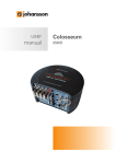
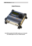
user manual Control Unit 6565 No part of this manual may be copied, reproduced, transmitted, transcribed or translated into any language without permission. Unitron reserves the right to change the specifications of the hardware and software described in these manuals at any time. Unitron can not be held liable for any damages resulting from the use of this product. Specifications are subject to change without notice. 09/11 © Unitron - Frankrijklaan 27 - B-8970 Poperinge - Belgium T +32 57 33 33 63 F +32 57 33 45 24 email [email protected] www.johansson.be - www.unitrongroup.com 2 CONTENTS 1 INTRODUCTION control unit................................................................................................................................. 4 package contents..................................................................................................................... 5 safety instructions.................................................................................................................... 6 2 MODULE OVERVIEW............................................................................................................ 8 3 WORKING WITH THE DEVICE using the rotary button............................................................................................................. 9 the screen................................................................................................................................ 10 menu structure........................................................................................................................ 11 start screen......................................................................................................................... 11 select language.................................................................................................................. 11 LED torch............................................................................................................................. 12 start scan............................................................................................................................. 12 connect with the device to setup.................................................................................... 12 example................................................................................................................................ 13 4 TECHNICAL SPECIFATIONS............................................................................................ 14 5 CONDITIONS OF WARRANTY......................................................................................... 15 3 1 INTRODUCTION Control Unit » REF. 6565 control unit for programming of compatible Johansson products via coax: 6620/6621/6622/6623/6630/6631 powered through coax cable or with power adapter (delivered with control unit) store/import of configuration easy operation: rotary/push button clear 2,7” OLED display: 128x64 pixels LED torch 4 PACKAGE CONTENTS Be sure all items listed below are included: 1 control unit (ref. 6565) 1 coax cable: black/1m 1 power adapter: 5V/2A 1 user manual 5 SAFETY INSTRUCTIONS Read these instructions carefully before connecting the unit To prevent fire, short circuit or shock hazard: Do not expose the unit to rain or moisture. Install the unit in a dry location without infiltration or condensation of water. Do not expose it to dripping or splashing. Do not place objects filled with liquids, such as vases, on the apparatus. If any liquid should accidentally fall into the cabinet, disconnect the power plug. To avoid any risk of overheating: Install the unit in a well aery location and keep a minimum distance of 15 cm around the apparatus for sufficient ventilation. Do not place any items such as newspapers, table-cloths, curtains,… on the unit that might cover the ventilation holes. The unit must not be exposed to any source of heat (sun, heater,...). Do not place any naked flame sources, such as lighted candles, on the apparatus. Do not install the product in a dusty place. Use the apparatus only in moderate climats (not in tropical climates). Respect the minimum and maximum temperature specifications. 6 To avoid any risk of electrical shocks: Connect apparatus only to socket with protective earth connection. The mains plug shall remain readily operable. Pull out power plug to make the different connections of cables. To avoid electrical shock, do not open the housing of adapter. Maintenance Only use a dry soft cloth to clean the cabinet. Do not use solvent. For repairing and servicing refer to qualified personnel. Dispose according your local authority’s recycling processes 7 2 MODULE OVERVIEW 1 2 3 4 1 1 5 control port: connect this port with the control port of the device to program the control port is indicated with a specific arrow 2 OLED display 3 rotary button 4 LED 5 power connection* * Some devices have a control port which delivers power to the control unit. In this case, the power adapter is not needed. However, you can also connect the control unit to another output of the device (in case of a profiler). This enables you to program the device from a remote location inside the building (e.g. from a wall outlet). When doing this, you need to connect the power adapter. Read the manual of the device to see if you need a power adapter. 8 3 WORKING WITH THE DEVICE USING THE ROTARY BUTTON The button of the control unit can be used to scroll through the menus: to scroll up, turn the button to the left to scroll down, turn the button to the right select by pushing the button down SELECT SCROLL UP SCROLL DOWN 9 THE SCREEN 1 2 3 1 HEADER title of the current menu 2 CURSOR BOX indicates what item is currently selected scroll to the item you wish to select 3 SCROLLBAR if there are more than 3 menu items, you will need to scroll down to see the next items 4 4 10 when an item is selected, the colours invert, showing you can set its value scroll the button to change te value press again to confirm the new value MENU STRUCTURE Because the control unit is compatible with different products, the menu is specific for the device you connect with. The device menu is found in the user manual of that specific device. The top level of the menu structure is identical for every device: device specific menu START SCREEN When connecting the 6565 with the device to program, the screen will light up, and the start screen will appear. Start scan - start scanning for devices on the coaxial bus Select language - select the language of the control unit Light ON - enable/disable the LED torch SELECT LANGUAGE Scroll to the SELECT LANGUAGE menu item to select the language of the device. Following languages are supported: English Français 11 LED TORCH To turn on the LED torch, navigate to the menu item LIGHT ON and press the button. The LED on top of the device will now turn on. To disable, click LIGHT OFF. START SCAN To enter the device, connect the control port of the control unit (on top of the device) to the control port of the device to program. Press START SCAN to connect with the device. The control unit is now scanning for devices. This can take up to 30 seconds. CONNECT WITH THE DEVICE TO SETUP When a device is found, the device menu appears: Settings - enter the device specific settings Import preset - import settings from the device to the control unit, for reproduction in other devices. Send preset - send a preset from the control unit to the device. Device info - specific device info Back - return to the previous menu The settings are device specific and the menu is found in the manual of that device. 12 EXAMPLE To demonstrate the use of the control unit, we explain how to configure a filter of the Profiler. We select F1, to configure the first filter of the device. The following menu items are shown: Start ch. - start channel of the band pass filter. [Channel 21-69] Stop ch. - cut-off channel of the filter. Configurable between 1 and 7 channels width. [0-6 UHF channels above start channel] Gain - Manual adjustment of the filter gain. [0-30 dB] Run auto level - the device will automatically set the gain of the filter, depending on the input level. Back - return to the main menu After all settings have been set, navigate to the menu item STORE ALL. This will save the configuration on the device 13 4 TECHNICAL SPECIFICATIONS 6565 CONTROL UNIT OPERATING VOLTAGE RF CONNECTORS POWER CONNECTOR DIMENSIONS 14 5-24 V 1 x F connector 2.1 mm power jack 176 x 83 x 43 mm 5 CONDITIONS OF WARRANTY PERIOD OF WARRANTY Unitron N.V. warrants the product as being free from defects in material and workmanship for a period of 24 months starting from the date of production indicated on it. See note below. If during this period of warranty the product proves defective, under normal use, due to defective materials or workmanship, Unitron N.V, at its sole option, will repair or replace the product. Return the product to your local dealer for reparation. THE WARRANTY IS APPLIED ONLY FOR DEFECTS IN MATERIAL AND WORKMANSHIP AND DOES NOT COVER DAMAGE RESULTING FROM • Misuse or use of the product out of its specifications. • Installation or use in a manner inconsistent with the technical or safety standards in force in the country where the product is used. • Use of non-suitable accessories (power supply, adapters ...). • Installation in a defect system. • External cause beyond the control of Unitron N.V. such as drop, accidents, lightning, water, fire, improper ventilation… THE WARRANTY IS NOT APPLIED IF • Production date or serial number on the product is illegible, altered, deleted or removed. • The product has been opened or repaired by a non-authorised person. NOTE Date of production is MMYY format, example 0411 = April 2011. For the serial number barcodes, the date corresponds to the 4 first numbers. 15 www.unitrongroup.com UNITRON NV Frankrijklaan 27 B-8970 Poperinge Belgium T +32 57 33 33 63 F +32 57 33 45 24 [email protected] www.johansson.be