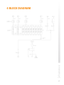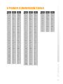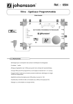
1
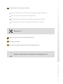
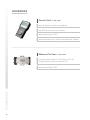
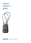
installation
guide
Super Profiler
6630
No part of this manual may be copied, reproduced, transmitted, transcribed or translated into any
language without permission.
Unitron reserves the right to change the specifications of the hardware and software described in
these manuals at any time.
Unitron can not be held liable for any damages resulting from the use of this product.
Specifications are subject to change without notice. 09/11
© Unitron - Frankrijklaan 27 - B-8970 Poperinge - Belgium
T +32 57 33 33 63 F +32 57 33 45 24
email [email protected]
www.johansson.be - www.unitrongroup.com
2
CONTENTS
1INTRODUCTION
the Profiler range...................................................................................................................... 4
package contents..................................................................................................................... 7
safety instructions.................................................................................................................... 8
accessories............................................................................................................................. 10
2 INSTALLATION OF THE HARDWARE
module overview..................................................................................................................... 11
3 CONFIGURATION OF THE DEVICE
control unit............................................................................................................................... 13
PC control................................................................................................................................. 14
4 BLOCK DIAGRAM................................................................................................................ 15
5 TECHNICAL SPECIFATIONS............................................................................................ 16
6 CONDITIONS OF WARRANTY......................................................................................... 17
7 FREQUENCY TABLE............................................................................................................ 18
8 POWER CONVERSION TABLE......................................................................................... 19
3
1INTRODUCTION
THE PROFILER RANGE
Profiler Plus
10 clusters » REF. 6620
10 highly selective filters (1-7 channels)
4 UHF inputs
FM/VHF/AUX input
high output power: >120 dBµV
2 programmable outputs
Profiler Plus SAT
10 clusters » REF. 6621
10 highly selective filters (1-7 channels)
4 UHF inputs
SAT input
FM/VHF/AUX input
high output power: >120 dBµV
2 programmable outputs
4
Profiler Plus
12 clusters » REF. 6622
12 highly selective filters (1-7 channels)
4 UHF inputs
FM/VHF/AUX input
high output power: >120 dBµV
2 programmable outputs
Profiler Plus SAT
12 clusters » REF. 6623
12 highly selective filters (1-7 channels)
4 UHF inputs
SAT input
FM/VHF/AUX input
high output power: >120 dBµV
2 programmable outputs
5
Super Profiler » REF. 6630
2 super selective filters: 30 dB @ 1 MHz
8 highly selective filters (1-7 channels)
frequency conversion functionality
4 UHF inputs
FM/VHF/AUX input
high output power: >120 dBµV
2 programmable outputs
Super Profiler SAT » REF. 6631
2 super selective filters: 30 dB @ 1 MHz
8 highly selective filters (1-7 channels)
frequency conversion functionality
SAT input
4 UHF inputs
FM/VHF/AUX input
high output power: >120 dBµV
2 programmable outputs
6
PACKAGE CONTENTS
Be sure all items listed below are included:
1
Profiler Plus module (ref. 6630)
1
power cord
1
user manual
7
SAFETY INSTRUCTIONS
Read these instructions carefully before connecting the unit
To prevent fire, short circuit or shock hazard:
Do not expose the unit to rain or moisture.
Install the unit in a dry location without infiltration or condensation of water.
Do not expose it to dripping or splashing.
Do not place objects filled with liquids, such as vases, on the apparatus.
If any liquid should accidentally fall into the cabinet, disconnect the power plug.
To avoid any risk of overheating:
Install the unit in a well aery location and keep a minimum distance of 15 cm around the apparatus for sufficient ventilation.
Do not place any items such as newspapers, table-cloths, curtains,…
on the unit that might cover the ventilation holes.
The unit must not be exposed to any source of heat (sun, heater,...).
Do not place any naked flame sources, such as lighted candles,
on the apparatus.
8
Do not install the product in a dusty place.
Use the apparatus only in moderate climats (not in tropical climates).
Respect the minimum and maximum temperature specifications.
To avoid any risk of electrical shocks:
Connect apparatus only to socket with protective earth connection.
The mains plug shall remain readily operable.
Pull out power plug to make the different connections of cables.
To avoid electrical shock, do not open the housing of adapter.
Maintenance
Only use a dry soft cloth to clean the cabinet.
Do not use solvent.
For repairing and servicing refer to qualified personnel.
Dispose according your local authority’s recycling processes
9
ACCESSORIES
Control Unit » REF. 6565
control different Johansson products
big OLED display for easy reading
operating voltage: 5-24V
power through coax cable or with delivered adapter
Ethernet-To-Coax » REF. 6564
control profiler products by PC (this unit is the
bridge between the coax and the PC)
operating voltage: 5-24V
10
2INSTALLATION OF THE HARDWARE
MODULE OVERVIEW
1
7
1
8
60 mm
2
3
4
5
220 mm
6
9
325 mm
1 hole for mounting screw
2 SAT input (6621 / 6623 / 6631 only)
3 BI-FM input
4 BIII-DAB input
5 UHF input 1
6 UHF input 2
7 UHF input 3
8 UHF input 4
9 detachable power supply
11
7
1
2
1 power cord connection
2 hole for mounting screw
3 AUX (VHF-UHF) output
4 TV output 2
5 TV output 1 & control unit input
6 test output (-30 dB)
7 detachable power supply
12
3
4
5
6
1
3CONFIGURATION OF THE DEVICE
There are two ways of configuring the Profiler. In both cases, you need an optional accessory. The operation of these accessories is described in the respective manuals.
CONTROL UNIT
The device can be controlled by means of a separate control unit (ref. 6565), which is
connected to the test output port of the unit.
Operation of the control unit is described in the user manual of the device (ref. 6565).
13
The operation of the control unit (ref. 6565) is explained
in the manual of the 6565. The menu structure of the profiler
is shown in the following picture:
PRESS 3 S
PRESS 3 SECO
14
SECONDS
ONDS
15
PC CONTROL
The device can be controlled by PC with our advanced UUI (Universal User Interface).
You need an Ethernet to Coax adapter (ref. 6564) and the UUI software. The UUI gives
access to all possible functionalities of the hardware and allows an easy and convenient way of configuring the device.
Ethernet to Coax
adapter
ref. 6564
Operation of the Ethernet to Coax module and the UUI are described in the respective
user manuals.
16
4 BLOCK DIAGRAM
17
5 TECHNICAL SPECIFICATIONS
6630
BI-FM
BIII/
DAB
AUX
47-68
88-108
174-240
47-862
GAIN* (dB)
35
40
30
60
ATTENUATOR (dB)
20
20
20
30
SLOPE ADJUSTMENT (dB)
-
-
-
-
GENERAL UHF LEVEL
ADJUSTMENT (dB)
-
-
SUPER PROFILER
FREQUENCY RANGE (MHz)
UHF1
UHF3
UHF4
470-862 470-862 470-862 470-862
-
FILTER BANDWIDTH (MHz)
UHF2
8-56 (1 to 7 channels)
+10 to -10
NOISE FIGURE (dB)
7
5
15
6
MAX. INPUT LEVEL (dBµV)
80
80
80
105
MAX. OUTPUT LEVEL* (dBµV)
-60 dB IM 3
118
118
122
122
-
-
-
30 dB/1 MHz (2x super filters)
30 dB/16 MHz (8x cluster filters)
>10
>10
>10
>10
>10
>10
>10
-
yes
-
yes
yes
yes
yes
SELECTIVITY
RETURN LOSS IN / OUT (dB)
SELECTABLE REMOTE POWER
12-24V (100 mA in total)
OUTPUTS
POWER SUPPLY (V~)
OPERATING TEMPERATURE (°C)
DIMENSIONS (mm)
TV 1 / TV 2 / Test -30 dB + control
230-240
- 5 to + 50
325 X 220 X 60
* 1 output active (2 outputs active = - 5 dB)
18
6 CONDITIONS OF WARRANTY
PERIOD OF WARRANTY
Unitron N.V. warrants the product as being free from defects in material and
workmanship for a period of 24 months starting from the date of production indicated on
it. See note below.
If during this period of warranty the product proves defective, under normal use, due to
defective materials or workmanship, Unitron N.V, at its sole option, will repair or replace
the product. Return the product to your local dealer for reparation.
THE WARRANTY IS APPLIED ONLY FOR DEFECTS IN MATERIAL AND WORKMANSHIP
AND DOES NOT COVER DAMAGE RESULTING FROM
•Misuse or use of the product out of its specifications.
•Installation or use in a manner inconsistent with the technical or safety standards in force in the country where the product is used.
•Use of non-suitable accessories (power supply, adapters ...).
•Installation in a defect system.
•External cause beyond the control of Unitron N.V. such as drop, accidents, lightning, water, fire, improper ventilation…
THE WARRANTY IS NOT APPLIED IF
•Production date or serial number on the product is illegible, altered,
deleted or removed.
•The product has been opened or repaired by a non-authorised person.
NOTE
Date of production is MMYY format, example 0411 = April 2011.
For the serial number barcodes, the date corresponds to the 4 first numbers.
19
7 UHF FREQUENCY TABLE
TV band
Channel
Frequency MHz
IV
21
22
23
24
25
26
27
28
29
30
31
32
33
34
35
36
37
38
39
40
41
42
43
44
45
46
47
48
49
50
51
52
53
54
55
56
57
58
59
60
61
62
63
64
65
66
67
68
69
470-478
478-486
486-494
494-502
502-510
510-518
518-526
526-534
534-542
542-550
550-558
558-566
566-574
574-582
582-590
590-598
598-606
606-614
614-622
622-630
630-638
638-646
646-654
654-662
662-670
670-678
678-686
686-694
694-702
702-710
710-718
718-726
726-734
734-742
742-750
750-758
758-766
766-774
774-782
782-790
790-798
798-806
806-814
814-822
822-830
830-838
838-846
846-854
854-862
V
20
8 POWER CONVERSION TABLE
μV 75 Ω
dBμV
dBm
1
1.5
2
2.5
3
3.5
4
4.5
5
6
7
8
9
10
15
20
25
30
35
40
45
50
60
70
80
90
100
150
200
250
300
350
400
450
500
600
700
800
900
0
3.5
6
8.0
9.5
11
12
13
14
15.5
17
18
19
20
23.5
26
28
29.5
31
32
33
34
35.5
37
38
39
40
43.5
46
48
49.5
51
52
53
54
55.5
57
58
59
-109
-105.5
-103
-101
-99.5
-98
-97
-96
-95
-93.5
-92
-91
-90
-89
-85.5
-83
-81
-79.5
-78
-77
-76
-75
-73.5
-72
-71
-70
-69
-66.5
-63
-61
-59.5
-58
-57
-56
-55
-53.5
-52
-51
-50
mV 75 Ω
1
1.5
2
2.5
3
3.5
4
4.5
5
6
7
8
9
10
15
20
25
30
35
40
45
50
60
70
80
90
100
150
200
250
300
350
400
450
500
600
700
800
900
1000
dBμV
dBm
V 75 Ω
dBμV
dBm
60
63.5
66
68
69.5
71
72
73
74
75.5
77
78
79
80
83.5
86
88
89.5
91
92
93
94
95.5
97
98
99
100
103.5
106
108
109.5
111
112
113
114
115.5
117
118
119
120
-49
-45.5
-43
-41
-39.5
-38
-37
-36
-35
-33.5
-32
-31
-30
-29
-25.5
-23
-21
-19.5
-18
-17
-16
-15
-13.5
-12
-11
-10
-9
-5.5
-3
-1
+0.5
+2
+3
+4
+5
+6.5
+8
+9
+10
+11
1
1.5
2
2.5
3
3.5
4
4.5
5
6
7
8
9
10
120
123.5
126
128
129.5
131
132
133
134
135.5
137
138
139
140
+11
+14.5
+17
+19
+20.5
+22
+23
+24
+25
+26.5
+28
+29
+30
+31
21
22
23
www.unitrongroup.com
UNITRON NV
Frankrijklaan 27
B-8970 Poperinge
Belgium
T +32 57 33 33 63
F +32 57 33 45 24
[email protected]
www.johansson.be