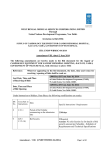
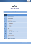
1
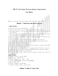
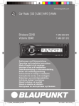
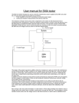
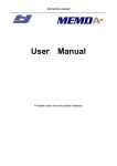
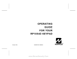
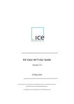
International Journal of Computer Applications (0975 – 8887)
Volume 38– No.1, January 2012
Microcontroller based Intelligent Digital Volume
Controller with Timer
Diptarup Paul
Sukalyan Som
Department of Computer Science and Engineering
JIS College of Engineering
Kalyani, Nadia-741235, West Bengal, India
Department of Computer Science
Barrackpore Rastraguru Surendranath College
85, Middle Road & 6, Riverside Road, Kolkata– 120
ABSTRACT
In this paper a Microcontroller based intelligent digital
volume controller is presented to control music system and
PC speaker volume digitally and change volume levels
automatically in case of certain predefined incidents such as
incoming or outgoing telephone call and pre-set alarm. The
device is constructed with AT89S52 microcontroller, from
ATMEL family with 8051 architecture, and its software
program being written in C language.
pointers, three 16-bit timer/counters, a six-vector two-level
interrupt architecture, a full duplex serial port, on-chip
oscillator, and clock circuitry.
Keywords
Microcontroller, AT89S52, CD4066, optocoupler, Zener
diode, Seven-segment display, voltage divider.
1. INTRODUCTION
The project is aimed at being a regular household product.
This not only has a digitalized volume control mechanism of
music system but also includes intelligent decision making to
change the volume level for certain incidents. For how many
times we have faced inconvenience to attend a phone call
when music is playing loud in our room? Well, this device
brings the solution. It automatically tracks the telephone line
and detects an incoming call, and brings down the volume to a
much lower definable level. Same thing happens for outgoing
calls too. And yes, this can be done manually as well!
The device also contains a clock, implemented with computer
software, by which we can set an alarm, and also set different
volume levels for a particular time of the day. That means an
alarm clock, but with a brain.
Fig 1: Pin Configuration of AT89S52.
Volume levels are being switched by the help of analogue
switching IC, CD4066. CD6044 is a quad bilateral switch[2],
i.e. it consists of four independent bilateral switches. A single
control signal is required per switch. Both the p and n device
in a given switch are biased ON or OFF simultaneously by the
control signal. As shown in Figure 2, the well of the n-channel
device on each switch is either tied to the input when the
switch is ON or to VSS when the switch is OFF.
For example: Let the time be set at 10 PM in the clock, the
clock is there to decrease the volume at 10 PM, without ones
interference, keeping one busy on what one is up to.
In case a user wants to use this device with his computer
speaker system there is an option for him to manage the alarm
system from the computer itself. Yes! This device can be
controlled from the computer by the means of serial
communication.
2. BASIC TERMINOLOGY
A micro controller is a small computer on a single integrated
circuit containing a processor core, memory, and
programmable input/output peripherals where peripherals can
be any electronic device.
As the name suggests, the device is controlled by a
microcontroller, AT89S52 [1], from Atmel Corporation.
AT89S52[1] (see Figure 1), is a 40 pin low-power, highperformance 8-bit microcontroller with 8 kilo bytes of insystem programmable Flash memory, 256 bytes of Random
Access Memory, 32 I/O lines, Watchdog timer, two data
Fig 2: Schematic diagram of CD4066.
The device is being switched though the telephone line by the
help of an optocoupler (also called opto-isolator,
phototransistor). It is an electronic device designed to transfer
electrical signals by utilizing light waves to provide coupling
with electrical isolation between its input and output. The
main purpose of an opto-isolator is to prevent high voltages or
19
International Journal of Computer Applications (0975 – 8887)
Volume 38– No.1, January 2012
rapidly changing voltages on one side of the circuit from
damaging components or distorting transmissions on the other
side [3]. The working is shown in Figure 3, where side 1, 2
acts as input, i.e. anode and cathode respectively and 3, 4 as
output, i.e. collector and emitter respectively.
.
Fig 5: Schematic view of a 7 segment display.
Fig 3: Schematic of an optocoupler.
The standard voltage for the telephone system is 48 volts DC.
Ringing voltage is much higher, around 90 volts AC at a low
frequency. So the opto-isolator prevents the main circuit from
this high voltage and also helps in switching when the phone
rings.
A Zener diode, or breakdown diode is a special kind
of diode which allows current to flow in the forward direction
in the same manner as an ideal diode, but will also permit it to
flow in the reverse direction when the voltage is above a
certain value known as the breakdown voltage, "Zener knee
voltage" or "Zener voltage"[4]. Break down diodes Are p-ndiodes operated in the breakdown region of the reverse
voltage characteristics [5]. In this circuit a 13 volte zener
diode has been used in the telephone line before the
optocoupler to ensure that it only acts for voltage levels more
than 13 volts, i.e. the condition when the telephone receiver is
down.
The volume levels are defined by the help of series voltage
dividers. In electronics, a voltage divider (also known as a
potential divider) is a simple linear circuit that produces an
output voltage (Vout) that is a fraction of its input voltage
(Vin). Voltage division refers to the partitioning of a voltage
among the components of the divider [6]. Figure 6 is a
representation of a voltage divider.
Fig 6: Voltage divider
3. PROPOSED LAYOUT
3.1 Idea about the project
The purpose of this project is to develop a digital volume
controlling device that is capable of controlling the volume of
a music system and PC speaker system to a predefined
volume level when the user is receiving a phone call in his
land phone. There will be provision for the user to control the
device from the computer if he wants to. Moreover the user
will be given a option to adjust the volume to a predefined
level at a particular time of the day by the clock implemented
in the computer software provided along with the device.
Fig 4: Zener diode.
In the above figure (Figure 4), a typical Zener diode has been
represented.
The volume level and other options are being displayed in a 7
segment display. Seven-segment displays are widely used in
digital clocks, electronic meters, and other electronic devices
for displaying numerical information. It contains 7 LEDs
arranged in such a manner that when illuminated accordingly,
can display numerical digits. It is of two types, common
anode and common cathode. The schematic of a 7 segment
display is shown in Figure 5. Common anode 7 segment
display is used in this project.
3.2 Presently available options
Presently, available volume controllers with timer are mainly
software based, i.e. they are usable in a computer only and no
hardware implementable volume controller with telephone
based intelligence is available. For example, Alarm[7], Cool
Timer[8], Timeleft [9] etc.
The existing softwares mentioned here have the following
generic features.
a. They act as a reminder on an oncoming event.
b. Tracks the amount of time left for specified event.
c. They are capable of being a countdown timer and sound
an alarm when the alarm goes off.
Existing softwares provide alarm facility by means of
software and are meant explicitly for PC use. The volume
levels cannot be controlled automatically by the softwares
users’ choice
20
International Journal of Computer Applications (0975 – 8887)
Volume 38– No.1, January 2012
Thus it can be cited that, this device has the following edge
over the existing systems and/or software.
a.
b.
c.
d.
This is a general purpose digital volume controller for
both music system and PC.
It is an attempt to combine volume control with alarm by
the means of hardware.
It is a novel attempt that includes automatic volume level
changes in case of special incidents such as incoming
telephone call and also outgoing call attempts.
Volume levels can be set by the user, according to the
need.
3.3 Working principle
The main system runs on a AT89S52[1] microcontroller, with
a 7 segment display to display the volume level, with 4
analogue switches, CD41066, two for each channel, left
channel and the right giving us 8 defined sound levels. The
telephone line signaling if fed to the microcontroller through a
optocoupler. The serial communication procedure is
implemented for the communication with the computer by the
means of a USB to serial converter [10]. Switches for
increasing and decreasing volume digitally, muting audio,
telephone interfacing, alarm interfacing, volume defining are
being supplied. The following Figure 7 is a block
diagrammatical representation of the project plan.
The block diagrammatical representation of sound level
switching is shown in the above figure (see Figure 8). Where
L0 is the mute condition and Ln is the highest volume level.
R1, R2, R3, …. , Rn are resistors of equal value. In this project
eight resistors are being used against each of channel left and
right. To get 8+1 i.e. 9 distinct sound levels.
3.4 Circuital implementation and control
description
The working model of the device is made a quite user
friendly. The circuit diagram is shown in Figure 9. Switches
S1 to S6 are configured as VOLUME UP, VOLUME DOWN,
LOW, LOW SET, TEL VOL and TEL BREAK respectively.
VOLUME UP key is programmed to increase the volume of
the system, as because this system comes with a built-in
volume controller.
VOLUME DOWN key is programmed to decrease the volume
of the system.
TEL VOL key is programmed to set the volume of the
speaker system, i.e. the volume level that the speaker system
will be playing in, when the telephone is in use. It can be ‘0’
i.e. mute, or any level user wants it to be.
LOW SET is to set the volume level of the LOW button
operation, if in this case the volume level is set to 0, it can act
as mute button, depending upon the user’s will.
TEL BREAK button is to bypass the telephone interfacing. If
when the music is silenced by the device and the user wants to
resume it to the volume it was playing, pressing this button
will bypass the silenced condition till the end of the call.
A telephone interfacing female socket, RJ11 is attached to the
telephone input part of the circuit.
Audio sockets are attached at LINE IN and LINE OUT. S7 is
a DPDT switch to bypass the audio line from the circuit. A
USB to Serial converter [10] connected to this device for
serial communication with a computer.
Fig 7: Volume control system functional block diagram.
The sound level switching is implements by the means of
voltage dividing with resistors attached in series and having
input audio signal at one end and GND at the other.
The functional description, in other words, the user manual to
operate the system, is stated as follows,
a.
A telephone interfacing female socket, RJ11 is attached
to the telephone input part of the circuit.
b.
Audio sockets are attached at LINE IN and LINE OUT.
S7 is a DPDT switch to bypass the audio line from the
circuit. A USB to Serial converter [10] connected to this
device for serial communication with a computer.
Fig 8: Sound level switching implementation block
diagram.
21
International Journal of Computer Applications (0975 – 8887)
Volume 38– No.1, January 2012
Fig 9: Circuit Diagram
c.
The device is connected to PC or any audio device and
the speakers are connected to this device.
m. If the present volume level is lower than the ‘low set
value’, the LOW button is not going to work.
d.
Telephone line is connected to the RJ 11 socket in
parallel to the main telephone line.
n.
To denote the LOW state, the 7-Segment Display
alternately glows ‘Dp’ and ‘the set level’.
e.
Audio input is taken and set in to the voltage divider,
created by resistances in series.
o.
f.
From every point in the voltage divider ladder, output is
taken.
When the telephone receiver is picked up, for receiving a
call or to make a call, the volume level jumps to a predefined level 1, or a user defined value.
p.
The volume level moves back to normal when the
telephone receiver is put back into place. After
completing the call.
q.
To set the volume level during the telephone call, the
TELVOL button is pressed after taking the volume level
to the desired volume level being shown in the 7segment display, while the telephone line is not being
used. This volume level is now set to be used during the
call.
g.
The outputs are channeled to the Analogy Switching IC
CD4066 as input.
h.
The switches in CD4066
microcontroller AT89S52[1].
i.
Volume can be increased or decreased up pressing
VOLUME UP and VOLUME DOWN button
respectively.
j.
The present volume level is displayed in the 7-Segment
Display.
r.
To denote the land phone call state, the 7-Segment
Display alternately glows ‘g’ LED and ‘the set level’.
k.
On pressing the LOW button, the volume is decreased to
a certain pre-defined level, and on pressing it for the
second time or UP or DOWN buttons, swaps back to the
earlier set volume level.
s.
In case of parallel connection in ones’ home, the
telephone interference can be bypassed by pressing the
TEL BREAK key, which resets itself with the end of the
call.
l.
The volume level for this case can be defined by pressing
the LOW SET button, which is pre-defined to 1. The
volume level shown in the 7-segment display is now set
to be used as the low. To set this level, the user has to
take the volume level to the level he needs to set as
LOW, by pressing the VOLUME UP and VOLUME
DOWN keys and press the LOW SET key.
t.
The telephone interference can be recalled by pressing
the TEL BREAK button again while the telephone line is
being used.
u.
This device can be operated from the PC itself and in that
case, the PC can act as the timer. In this case one can set
are
driven
by
the
22
International Journal of Computer Applications (0975 – 8887)
Volume 38– No.1, January 2012
the time to either increase or decrease the volume to the
level, set by the LOW SET button.
The device runs on 5 volts DC. To power this device one can
use a DC adaptor ranging from 6 to 15 volts. The voltage is
stepped down to 5 volts be the use of a voltage regulating IC
LM317.]
100 ohms and R3 is 560 ohms. V IN can be any voltage
between 6V to 15V. VOUT is 5V. The datasheet of LM317
[11] and online calculator[12] has been consulted for the
values of R1, R2 and R3.
3.5 Flow chart
The flow chart follows in Figure 11.
4. SOFTWARE INTERFACE
Fig 10: LM317 voltage regulation block diagram.
In the above diagram (Figure 10) voltage regulating
implementation with IC LM317 is shown which is used to
generate 5 voltage for the circuit. Here R1 is 220 ohms, R2 is
This device comes with a computer software. This interface
has been developed with Microsoft Visual Basic 6.0. This
software is optional to a user. The privilege a user gets, while
using this software is that, he gets the option to set timer to
control the device. This timer helps him to switch the device
to LOW volume level, i.e. the operation he gets by pressing
the LOW key in the hardware. But in this case the software is
there to make him lazy. The only thing he has to do is to plug
the device to his computer USB port, run this software and set
the time. The software will do the rest. The following figure
(see Figure 12) shows a screen shot of the software in action.
Fig 12: Software interface.
The functionality of each button of the software is stated as
follows,
Volume+ – This button will increase the volume level in the
device by level 1, the same way the VOLUME UP key acts in
the hardware device.
Volume- – This button will decrease the volume level in the
device be level 1, the same way the VOLUME DOWN key
acts in the hardware device.
Set Alarm Time – This is the text area where the user is
required to type in the time in hour, minute, and second in
HH:MM:SS format.
Set Alarm – This button sets the time entered in the text areas
of Set Alarm Time. If any of the text boxes are left as blank
by the user then it takes default value as 0. At this particular
time the device will switch itself to LOW state and vice versa,
provided the device has to remain connected to computer.
Set low – Thus button will set the volume level of the low
volume level same as LOW SET in the hardware.
Decrease now – This button will decrease the volume level to
LOW. The functionality of the button is same as that of the
LOW key in the hardware.
Current time – It shows the system time in 24 hour format
from the computer.
Present Volume Level – This shows the volume level the
hardware is set to. It is volume level which is being displayed
in the 7-segment display in the hardware.
23
International Journal of Computer Applications (0975 – 8887)
Volume 38– No.1, January 2012
START
1
YES
INITIATE DEVICE WITH DEFAULT VALUES AT INPUT
AND OUTPUT PINS OF THE MICROCONTROLLER
YES
TEL BREAK KEY
IF
TELEPHONE LINE IN
USE
NO
INTIATE SERIAL COMMUNICATION
NO
DISABLE TELEPHONE
IGNORE AND SWITCH
KEPT
NITIATE A VOLUME LEVEL COUNTER AT A DEFAULT VALUE
YES
IF
TELEPHONE
CONDITION IS
SYSTEM VOLUME TO
LEVEL ‘TEL’
IGNORED
LOOP BEGIN
ENABLE TELEPHONE IGNORE
NO
AND SWITCH SYSTEM VOLUME
BACK TO NORMAL
CHECK KEYPAD FOR INPUT AND
SERIAL PORT FOR DATA
SERIAL
COMMAND TO
INCREASE VOLUME
OR VOLUME UP
KEY
NO
IF
TELEPHONE
LINE NOT IN USE
YES
INCREASE VOLUME
COUNTER BY 1
SERIAL
COMMAND TO
YES
DECREASE VOLUME OR
VOLUME DOWN
KEY
DECREASE VOLUME
COUNTER BY 1
NO
YES
DISABLE TELEPHONE
IGNORE AND SWITCH
SYSTEM VOLUME
BACK TO NORMAL
NO
CHECK
TIME TRIGGER
FROM COMPUTER THROUGH
SERIAL COMMAND
YES
NO
CHECK
IF PRESENT VOLUME
IS ‘LOW’
NO
SERIAL
COMMAND TO
SET LOW LEVEL OR
LOW SET KEY
VOLUME
YES
YES
STORE PRESENT VOLUME
SWITCH VOLUME
LEVEL TO THE
SWITCH
COUNTER VALUE IN A
VALUE SET IN
LEVEL
BACK TO
VARIABLE ‘LOW’
NO
VARIABLE ‘LOW’
WHERE IT
WAS
YES
TEL VOL KEY
NO
STORE PRESENT VOLUME
COUNTER VALUE IN A
VARIABLE ‘TEL’
DISPLAY VOLUME LEVEL IN THE 7-SEGMENT
DISPLAY
IN NORMAL CONDITION.
TOGGLE ‘Dp’ LED AND VOLUME LEVEL
IN LOW VOLUME CONDITION.
SERIAL
YES
CHECK
COMMAND TO
IF PRESENT
MUTE OR LOW
VOLUME IS
KEY
LOW
YES
NO
NO
SWITCH VOLUME
SWITCH VOLUME
LEVEL TO THE
LEVEL BACK TO
VALUE SET IN
WHERE IT WAS
VARIABLE ‘LOW’
TOGGLE ‘g’ LED AND VOLUME LEVEL
IN TELEPHONE ACTIVE CONDITION
SEND PRESENT VOLUME LEVEL OF THE SYSTEM, TO
THE
COMPUTER THROUGH SERIAL
COMMUNICATION.
CHECK IF
TELEPHONE LINE IS
IN USE
NO
IF
TELEPHONE
CONDITION IS KEPT
IGNORED
YES
GOTO BEGINING OF THE LOOP.
NO
YES
SWITCH VOLUME LEVEL TO THE VALUE SET IN
VARIABLE ‘TEL’
1
END
Fig 11: Flow Chart
24
International Journal of Computer Applications (0975 – 8887)
Volume 38– No.1, January 2012
5. FUTURE SCOPE AND CONCLUSION
7. REFERENCES
Following enhancements can be made individually on the
hardware part and the software part as follows.
[1] AT89S52
Datasheet,
http://www.atmel.com/dyn/
resources/prod_documents/doc1919.pdf
Hardware – In this device, the timer thing is implemented in
the software part and the volume change is being performed in
the hardware. The implementation of a hardware clock
attached to this device can make this thing work
independently. In that clock, alarm time can be set by the user
and the sound level will go down accordingly. The clock can
act as an alarm clock too on implementing a separate buzzer
with it. Further implementation of an IR remote with this
device can make it more efficient and help the user to control
the device from a distance. The volume level a user sets in the
system gets reset, once the device is restarted. Implementing,
a memory, i.e. an EEPROM with the device can solve the
problem.
[2] CD4066
4066.pdf
Software – The software that helps the user to interact with
the hardware can be made provided with more features, such
as, a countdown timer which will also help in the alarm
operation. A reminder facility to notify the user about his
scheduled works can be implemented. A stopwatch can also
be implemented along with the software. Provisions of setting
an alarm with date and not only time can be implemented
further.
This system came up as a need to a guy who is a music freak
and is clumsy with his stuffs. In this project, microcontroller
based intelligent digital volume controller with timer, we
designed a hardware that is capable of controlling volume of
any audio system and is also capable of switching volume
levels during incoming or outgoing phone calls in wired
network. The microcontroller programming is performed in
Embedded C. Each and every operation in this device is made
interactive and easy to recognize. The device surrenders itself
to its user’s will in case of volume levels. The computer
software is designed in such a way, that it can be easily
operated.
6. ACKNOWLEDGMENTS
The authors express a deep sense of gratitude to the
Department of Computer Science, JIS College of Engineering,
Kalyani, Nadia-741235, West Bengal, India and Department
of Computer Science, Barrackpore Rastraguru Surendranath
College, Kolkata-700 120, West Bengal, India for providing
necessary support for the work and their family members for
being constant inspiration and motivation for pursuing such
works.
Datasheet,
http://members.shaw.ca/roma/
[3] Opto-Isolator, http://en.wikipedia.org/wiki/Opto-isolator
[4] Zener-Diode, http://en.wikipedia.org/wiki/Zener_diode
[5] D. Chattopadhyay, P.C. Rakshit, New Age International
Publication,
Electronics
–
Fundamentals
and
Applications p. 72
[6] Voltage
divider
or
Potential
http://en.wikipedia.org/wiki/Voltage_divider
divider,
[7] Alarm
&
Clock
software
from
http://download.cnet.com/Alarm/3000-2350_410742679.html?tag=main;dropDownForm
CNET,
[8] Cool Timer from Harmony Hollow software,
http://www.harmonyhollow.net/cool_timer.shtml
[9] Time
Left
is
a
timer
http://www.timeleft.info/timer-software.html
Software,
[10] AVR CDC, http://www.recursion.jp/avrcdc/
[11] LM317 Datasheet,
lm117.pdf
http://www.ti.com/lit/ds/symlink/
[12] LM
317
Calculator,
lab.com/articles/LM317/
http://www.electronics-
8. ABOUT THE AUTHORS
Diptarup Paul is presently working as a Hardware and
Embedded System Research and Development Engineer in
Security Engineers Private Limited, West Bengal, India. He
has received his B. Tech in Computer Science from West
Bengal University of Technology, West Bengal, India. His
research interest includes Cryptography, Steganography,
Microcontroller and Microprocessor, Biometric Sensors,
RFID.
Sukalyan Som is presently working as an Assistant Professor
in Computer Science in Barrackpore Rastraguru Surendranath
College, West Bengal, India. He is having over 5 years of
teaching experience. He has received his B.Sc. in Statistics
from University of Calcutta, West Bengal India and Masters
in Computer Application from West Bengal University of
Technology, West Bengal, India. His research interest
includes Cryptography, Steganography, Image Processing,
Computational Geometry etc.
25
International Journal of Computer Applications (0975 – 8887)
Volume 38– No.1, January 2012
Fig 13: Microcontroller Based Intelligent Digital Volume Controller with Timer (Front View).
Fig 14: Microcontroller Based Intelligent Digital Volume Controller with Timer (Top View).
26