1
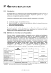
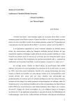
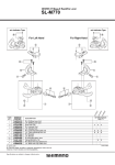
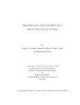
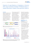
COOPERATIVE ROAD SIGN AND TRAFFIC LIGHT USING NEAR INFRARED
IDENTIFICATION AND ZIGBEE SMARTDUST TECHNOLOGIES
Axel von Arnim
LIVIC - LCPC
14, route de la Minière
78000 Versailles – France
[email protected]
Antoine Fusée
Budi Arief
LIVIC - LCPC
School of Computing Science
14, route de la Minière
Newcastle University,
78000 Versailles – France
Newcastle upon Tyne
[email protected]
NE1 7RU – UK
[email protected]
Abstract. Vehicle-to-vehicle (V2V) and vehicle-to-infrastructure (V2I as well as I2V)
applications are developing very fast. They rely on telecommunication and localization
technologies to detect, identify and geo-localize the sources of information (such as vehicles,
roadside objects, or pedestrians). This paper presents an original approach on how two
different technologies (a near infrared identification sensor and a Zigbee smartdust sensor)
can work together in order to create an improved system. After an introduction of these two
sensors, two concrete applications will be presented: a road sign detection application and a
cooperative traffic light application. These applications show how the coupling of the two
sensors enables robust detection and how they complement each other to add dynamic
information to road-side objects.
Keywords: sensor fusion, near infrared, smartdust, cooperative system, road sign detection,
intelligent traffic light
INTRODUCTION
Advances in technology affect many aspects of our live, including the way we travel and the
transportation systems in general. More and more vehicles are equipped with state of the art
equipments and sensors, and the road infrastructure is becoming smarter and provides
additional supports to the road users. First and foremost, these advances should be utilized to
improve road safety, for example, by reducing the number of accidents and minimizing those
that involve fatality or horrific injuries. On top of that, road travel experience can be made
more enjoyable thanks to intelligent transportation systems that reduce the effort required by
the drivers and the time saved through more efficient systems.
It is not possible to achieve all these by relying solely on one sensor technology. Multiple
sensors need to be deployed in order to build a complete system where one sensor’s
capabilities can complement others’. This is the approach we took in our work. Starting with
two individual sensors – a near infrared remote identification sensor and a Zigbee smartdust
communication device – each with its own features and limitations, we investigated how the
two can complement each other. For example, the near infrared identification sensor has a
very good range and localization features, but it relies on visual detection. This makes it prone
to errors when objects may obstruct the view, or in inclement weather conditions. On the
other hand, the Zigbee smartdust sensor cannot easily determine the location of a target (since
it relies on radio signal, which does not carry information on the detection direction), but the
radio signal is free from visual impairment. By combining the positive characteristics of these
-1-
two sensors, we have developed a new system that provides a more robust detection and
identification of objects on the road.
In this paper, we demonstrate the benefits of this collaboration through two applications:
• A road sign detection application
This application enables road signs on the side of the road to be detected, identified and
localized accurately in advance. As a result, drivers will become aware of the road
conditions with sufficient time to react, hence improving the road safety.
• A cooperative traffic light application
By knowing how much time is left for a particular colour of the traffic light, drivers can
plan when to change the movement of the vehicle (for example, whether they should be
preparing to move again after a stop), hence they can save time.
There are many other applications that can be constructed using this collaboration, but for
now, we will focus on the two above. But before we get into details with these two
applications, we will introduce each individual sensor and discuss their capabilities.
OPTICAL IDENTIFICATION SENSOR
General Overview of the Sensor
The Optical Identification Sensor was developed at LIVIC. Its purpose is to detect, identify
objects (vehicles or roadside objects) and localize them in the road scene. Coupled with a
radio-communication system, the sensor enables us to determine which object is the source of
a given message. It has been patented in 2007 (2).
Some systems use vision-based pattern (including license plate) recognition and they need
high resolution cameras and have low ranges. Other systems use infrared light for
classification purposes (4), or infrared beacons with a dedicated radio signalling protocol for
synchronization (5). Our sensor has a much higher range, and only needs a low-resolution
camera and a simple infrared beacon.
The sensor is composed of two parts, an Emitter part and a Receiver part. The Emitter is the
active part. It is a near-infrared led-based lamp (see Figure 1), which, thanks to an embedded
controller, codes an identifier (a number) using a defined frame protocol. The signal is thus
time-coded (blinking light) and not space-coded. This enables important ranges and
robustness enhancements, compared to traditional spatial-pattern-based identification
systems.
Figure 1: The emitter part of the optical identification sensor
-2-
This Emitter continuously emits a cycling frame, containing a start sequence (4 bits), the
usable code (identification number), a zero and a parity bit. Figure 2 shows the Emitter’s
frame protocol.
Previous frame
Start code
Id code
‘0’
Parity bit
Next frame
Figure 2: Emitter frame protocol
The Receiver is a high framerate, low-resolution CCD camera, equipped with an IR-bandpass
filter, plus a decoding algorithm. The full description of the algorithm can be found in (3),
here we will give a brief explanation about the decoding process.
A low-level algorithm processes the input image to extract the spots corresponding to the
emitters. Most of the false detections (which can be caused by other infrared sources such as
the sky or vegetation) are eliminated by shape analysis. The order of operations is:
1. IR-filtered image is acquired. Emitters appear like bright round spots
2. Image is converted to strict black and white using a threshold, so that only the brightest
pixels are kept (IR sources)
3. Regions are made more consistent, less fragmented, using morphological dilatation
4. White pixels are clustered: each connected region is a labelled cluster
5. Regions are accepted or rejected depending on their size and roundness. Large regions,
corresponding to the sky, and regions which do not look like a spot, for example pieces
of vegetation, are rejected.
Low-level image
analysis
=> targets
High level tracking
=> tracks
frame protocol
valid
y
e
s
n
o
reject
parity bit correct
y
e
s
Tracks filtering and
decoding
=> valid tracks
accept
n
o
reject
valid tracks
output
Absolute Localization
=> identified objects
Figure 3: Optical Identification decoding algorithm
Then, a high-level algorithm (Figure 3) tracks the detected spots over time (in successive
images) to follow their movement and analyze their logical state (0=un-lit, 1=lit). The
tracking algorithm uses a simple neighbourhood prediction technique. The resulting bit
stream, for each tracked spot, is continuously analyzed. If it conforms to the frame protocol, it
is accepted as a valid Emitter signal and the decoded identification number is output.
Finally, the (X,Y,Z) position of the identified and tracked Emitter is estimated from the (x,y)
position in the image, knowing the pitch angle of the Receiver-equipped vehicle, and the
height of the Emitter relative to the road surface. Indeed, Z (depth, or distance) is correlated to
the height in the image, with a given pitch angle, and a static road-Emitter vertical distance.
This estimation procedure is detailed in (3).
-3-
Sensor Capabilities
The efficiency of the sensor is due to the very low spatial and camera-resolution constraints,
and the tracking algorithm which rejects most of the false alarms caused by other nearinfrared emitters such as solar reflections, sky portions, vehicle- or traffic-lights. The sensor
can be tuned using 3 parameters:
• Receiver camera resolution: this parameter has influence on the accuracy of Z estimation.
The smaller the vertical resolution, the lower the accuracy.
• Receiver camera framerate: the higher this parameter, the higher the Emitter frequency
• Emitter frequency: the higher this parameter, the lower false detections (because the
Emitter signal evolves faster than environmental near-infrared signal like solar reflections
or blinking turn lights). The quicker the identification time, and the higher the tracking
efficiency
Camera capabilities and experimental tests led us to choose a Pulnix greyscale 200
images/second CCD camera. With a resolution of 320x120, and a corresponding maximum
framerate of 514 images/second, we were able to run the decoding algorithm in real-time,
allowing a 210Hz Emitter frequency. This configuration gives the following performances:
400m identification range in the best case (grey weather or at night), 110m identification
range in the worst case (very sunny weather), 100ms identification time (time between the
first appearance of an Emitter in the camera view and the delivery of its identification
number, with the tracking being performed at the speed of the Emitter, i.e. 210Hz). Actually,
the range is mainly determined by the power of the Emitter, which could easily be adapted
according to the light conditions: strong light → difficult conditions → increased emitting
power.
Figure 4 shows the detection ranges of three roadside objects. The vertical axis represents the
identification numbers of the objects (which are 9, 7, and 20 in this case). The horizontal axis
represents the distance covered by the vehicle, where the elevated lines signify the detection
of a particular roadside object. The vehicle was travelling at 50km/h in good weather
conditions. The detection in the middle (for roadside object with identification number of 7)
has more than 350m detection range.
Figure 4: Optical Identification Sensor detection range
These results, even in the worst-case scenario, are good enough to enable an efficient
detection and identification of objects by the Receiver travelling at the speed of up to
130km/h. This enables applications like localized vehicle-to-vehicle (V2V) communication,
road sign recognition, as well as long-range cooperative vehicle detection and tracking to be
developed.
-4-
The sensor however has a low, but not null, false-detection rate when used in bad conditions
(very sunny weather), because of the high number of near infrared sources, especially direct
sunlight through vegetation. This scenario generates hundreds of little blinking spots of
infrared light, that most of the time are eliminated by the high-level tracking algorithm, but in
rare cases can generate a false detection, lasting a couple of milliseconds. Of course, a toplevel filtering (on the minimum duration of a tracked detection) can eliminate this threat, but
this introduces some latency, wasting a couple of meters in the detection range, or fractions of
a second in the case of an appearing object.
Concerning the accuracy of localization of identified objects, the lateral positioning on the
road has a precision of one meter at 40 meters distance. This is enough to determine on which
driving-lane the object is, with a good detection range. The longitudinal positioning (distance)
is less accurate, but this is not so important in our case. This distance measurement can be
enhanced by increasing the vertical resolution of the camera, which we do not want to do,
since we aim to use a low-resolution, low-cpu consumption Receiver. The details are
presented in (3).
With these capabilities, the following applications were successfully developed:
• Localized vehicle-vehicle communication
Attached at the rear of vehicles, the Emitter lets these vehicles to be detected, identified
and tracked by a Receiver-equipped vehicle. So, coupled with a radio-communication
system (WiFi for example), it becomes possible for the Receiver-equipped vehicle to
localize on the road the sources of inter-vehicle messages. In a hazard-warning application,
this enables filtering of messages with regard to whether their source is a vehicle in the
same lane as the Receiver vehicle or not. For example, a vehicle detecting a dangerous
curve (by ESP activation) can broadcast this information through WiFi, and the following
vehicle, getting this message and knowing – thanks to our sensor – that the message comes
from the followed vehicle, takes this information into account. The same goes for an
emergency braking warning application (see Figure 5). These applications have been
implemented, tested and presented in September 2007 to an audience of people from the
PIARC world congress in Paris, France (8).
Figure 5: Emergency braking application screen capture
• Road sign recognition
Attaching the Emitter to a road sign enables an approaching vehicle to detect and identify,
i.e. to recognize the road sign, within the sensor range. The Emitter codes an identification
frame characterizing the type of road sign. Additional information can be added to the
-5-
Emitter, like advised speed for a dangerous curve road sign for example. During the time
that the road sign is being detected, it is also localized, and a symbolic representation of it
can be projected inside the filmed scene. Two example graphical displays can be seen on
Figure 6. The left one shows a symbolic representation of the road sign and the right one
shows an “augmented reality” view, where the road sign is drawn at its real position on the
image. One can easily understand the benefit of this application for night-time driver
assistance. This application was implemented, tested and also presented at the PIARC
demonstration.
Figure 6: Graphical display for road sign recognition
• As our identification sensor is able to detect vehicles up to more than 300m, it can be used
for long range cooperative obstacle detection. Indeed, the detected Emitters can provide
seeds on a high resolution image where heavy computational image processing algorithms,
such as stereovision can then extract regions of interest to focus their calculations on. This
allows stereovision-applications to work with high resolution images in real-time, thus
dramatically increase their range.
ZIGBEE SMARTDUST SENSOR
General Overview of the Sensor
Smartdust (or mote) is a micro-electro-mechanical device, typically composed of a processing
unit, some memory, and a radio chip, which allows it to communicate wirelessly with other
smartdust devices within range. Depending on the radio chip, the wireless communication
operates in frequency bands around the 800-900MHz, 2.45GHz or 5.8-5.9GHz using
communication protocols such as IEEE 802.15.4 (Zigbee) (13). This wireless capability
makes it possible for smartdust devices to form a Mobile Ad-hoc NETwork (MANET) – a
collection of mobile computing devices which cooperate to form a dynamic network without
using fixed infrastructure.
These devices are programmable, and they can also be augmented with additional sensors
(such as those for detecting light, temperature and acceleration), hence enhancing their
features and making their application areas virtually limitless.
Smartdust’s main benefits are its characteristics of being highly portable and highly
customisable. These allow us to rapidly deploy them in almost any situation, and to develop
-6-
specific applications suitable to our need. It is also perceived that smartdust has the potential
to become the low-cost, ubiquitous sensor of the future.
Sensor Capabilities
We use off-the-shelf smartdust devices from Crossbow Technologies called MPR2400
MICAz motes (7). These motes are equipped with a Zigbee (13) radio chip, which enables
them to communicate with other MICAz motes or other Zigbee-ready devices within range
(approximately 70 meters). Figure 7 shows MPR2400 MICAz mote and its size comparisons.
Figure 7: MPR2400 MICAz mote
This mote can be programmed using a language called nesC on the TinyOS platform (9) and
it can be plugged-in to a programming board using the 51-pin Hirose connector. In turn, the
programming board is connectable to a laptop or a PC using either serial (RS-232), USB or
Ethernet cables. Through this programming board, new software can be uploaded onto the
mote. This board can also serve as a “base station”, acting as a gateway between the mote(s)
and the application running on the laptop (see Figure 8).
Keys:
Smartdust mote
Zigbee radio
Smartdust
Base
Station
Figure 8: Interaction with smartdust motes around the base station
By writing suitable software, we can interact wirelessly with these motes through the laptop.
This opens up a host of applications for smartdust, for example:
• Road sign recognition
We place several motes on the infrastructure (on the side of the road). Each mote is
programmed to broadcast a unique identity, representing a particular traffic sign. Each
mote is then placed next to the actual traffic sign. We equip a car with a laptop and a
smartdust base station, and when the car approaches the traffic sign, the base station will
pick up the identity of the smartdust on the side of the road. This is then processed by the
application on the laptop and an appropriate warning can be displayed (Figure 9). This
application will be discussed further in the next section.
-7-
50
10
50
30
Figure 9: Road sign recognition application using smartdust
• Vehicle detection and counting
Each vehicle is equipped with a smartdust broadcasting a unique identity. We put the
smartdust base station on the side of the road (as a monitoring station). When these
vehicles pass the monitoring station, they will be detected and counted. Since the
information broadcast by the smartdust motes can be customised according to our need,
this application can be extended by augmenting the broadcast data with – among others –
the vehicle classification and its registration number.
We had carried out tests investigating the feasibility of using smartdust in V2I and I2V
applications. There was initially some concern about the suitability of Zigbee radio for
applications involving vehicles moving at high speed (for example, due to the Doppler
Effect), but we have demonstrated that this is not really the case (6). From our tests, we also
worked out that the communication range of smartdust (between a moving vehicle and a
stationary object on the side of the road, or vice versa) is approximately 50 meters. We
envisage that there should be no problem in deploying smartdust in V2V applications.
One of the beneficial features of smartdust is that it does not need visual contact in order to
communicate with other smartdust devices around. This means smartdust does not suffer from
visual-related impairments (such as obstructive objects, shading, or inclement weather
conditions) which could affect a lot of camera-based sensors used in transport domain. On the
down side, the detection range of smartdust is rather limited. Although this does not cause
much problem in static settings (we can just add extra smartdust devices if we want to cover a
greater range or distance, hence creating several hop points or even a MANET), it might pose
some restrictions on its applicability in transport scenarios.
This is one of the areas that the TRACKSS project (11) aims to answer: how diverse sensors
and technologies can collaborate together in order to obtain better measures. A sensor’s weak
point can be overcome by making that sensor collaborate with another sensor that can address
the problem. At the same time, the first sensor might have features that can complement the
second sensor.
APPLICATIONS
For the demonstration, we equip a car with an optical identification receiver (camera), a
smartdust mote (sitting on its base station), and a computer connected to these sensors, on
-8-
which the applications controlling these sensors are running. We also place infrared emitters
and smartdust motes on the side of the road; they act as the broadcaster of signal for
representing the road signs and the traffic light. Figure 10 provides a diagrammatical
representation of this set-up.
Figure 10: The set-up of the equipments used in our applications
On the on-board computer, both sensors communicate using a unified library developed
within the TRACKSS project: the KSM, which stands for Knowledge Sharing Model. This
KSM is a middleware that encapsulates a common communication protocol of all the sensors
used in the TRACKSS project, turning these sensors into Knowledge Sharing Sensors (KSS).
A KSS uses this standard communication API (Application Programming Interface) as a
means for sharing information with other KSSs as depicted in Figure 11. The purpose of the
TRACKSS project is to make sensors collaborate using this generic middleware. Further
details on the TRACKSS KSM can be found in (1).
KSS sensor 1
KSS sensor 2
KSM
KSM
Driver
Driver
Hardware
Hardware
Figure 11: The KSM communication layer
Application to Cooperative Road Sign Detection
We combine the long detection-range capabilities of the near infrared camera with the visualindependence feature of the smartdust in order to develop a more robust system for road signs
detection.
In most cases, the near infrared camera picks up the signal from the infrared emitter prior to
the smartdust base station picking the signal from the smartdust mote on the side of the road.
In these cases, the latter provides a confirmation of the detected road sign to the former, hence
increasing the confidence of the result.
-9-
In other cases (for example, around the bend or if there is some visual impairment), the
smartdust picks up the road sign signal before the camera. The system will then warn the
driver that a road sign is detected nearby, but we do not have 100% certainty until this is
confirmed by the camera.
Application to Cooperative Traffic Light
In this application, we program the smartdust mote to mimic the behaviour of a traffic light,
including the time delays for each traffic light colour. This mote then continuously broadcasts
a signal representing the current colour displayed by the traffic light, as well as the time left
for that colour. The near infrared camera is used to pre-warn the driver regarding the presence
of the traffic light ahead (since it has a longer detection range than the smartdust), and to
initialise the traffic light display application on the car. Once the smartdust signal is picked up
by the smartdust base station on the car, the application will show the current traffic light
colour and its remaining time. The frequency of the smartdust broadcast is every 100ms,
enabling the application to show the time left for the current colour in the nearest (rounded
down) second.
This application has major advantages in terms of reduction of latency time when vehicles are
starting on green light. When all vehicles have the information in advance when the light gets
green, all the drivers can prepare for start, and save a couple of seconds per vehicle.
On the image below (Figure 12), you can see an example graphical user interface that we
propose. The time before colour change is shown on the top left of the drawn traffic lights.
Two kinds of interfaces are proposed: a symbolic one (on the left) showing only the traffic
light with the time left, or an “augmented reality” version, with the traffic light drawn on
overlay of the road scene. This latter version can be adapted to a head-up display device.
.
Figure 12: Graphical display for cooperative traffic light
A similar system had been developed by Toyota (10) using different technology.
Experimental Results
The first major experimental result of these applications is given by the fusion of
identification information from two different sensors with different technologies. When the
fusion strategy is a confirmation of one sensor by the other, then the limitations of each sensor
can be compensated.
- 10 -
The aforementioned false detections that can occur in difficult weather conditions with the
optical identification sensor are totally eliminated because they are not confirmed by a
smartdust signal. So, there is no need for a high-level filtering as explained above, which
means we save detection- and reaction-time. On the other hand, where the smartdust sensor
can not provide the precise relative position of a road sign, the optical identification sensor
gives sufficient accurate positioning to be able to decide if the road sign is on the driving lane
or another lane.
Concerning the detection range, with our confirmation strategy (where the target must be
within range to be simultaneously detected by both sensors), the final range is highly
influenced by the range of the smartdust sensor. This is because the optical identification
sensor has a much higher range than the smartdust sensor. But our application does not need a
range over hundreds of meters. It needs to be able to detect a road sign sufficiently early to
warn the driver or start an action, at any speed up to 130km/h. The range of smartdust is
sufficient. Anyhow, the range of smartdust sensor can be easily increased by chaining
multiple smartdust sensors in an ad-hoc network ahead of the road sign. The maximum range
of the optical identification sensor can then be covered.
The graphs below show the ranges of the optical identification sensor, the smartdust sensor,
and the coupled sensors at different speeds. When placed next to the optical identification
sensor, the smartdust continues the detection even after the road sign has been passed
(whereas the optical identification sensor ceases the detection after the road sign has been
passed). This is due to the fact that the smartdust sensor relies on a radio signal, which is not
directional but is based on the radius of the signal. This shows the benefits of the optical
identification sensor which provides the information that the road sign detected by the
smartdust is not relevant anymore since after it has been passed. On Figure 13, we placed the
smartdust 30m ahead of the actual road sign (with the identification emitter still placed next to
the actual road sign), so that the total range of smartdust is included in the range of the
identification sensor. The figure on the left shows the measurements at the speed of 50km/h,
whereas the figure on the right at the speed of 130km/h.
Figure 13: Application detection range
The smartdust range on the left figure is not included within the optical identification range,
but is in the right figure. This is due to smartdust range limitation when driving at high speed.
So we calibrated the optimized position for the smartdust sensor based on the range at
130km/h. You can also notice that the optical identification range is not as large as the one
presented above. This is due to the different weather conditions. Nevertheless, we reach more
than 200m range here.
- 11 -
CONCLUSION
This paper highlights the benefits of fusing information from two different sensors – optical
identification sensor and smartdust sensor – in order to create a more robust and improved
system. We have demonstrated the feasibility of this collaboration through two applications,
namely the cooperative road sign detection and the cooperative traffic light application.
Ideas of enhancements include a range extension for smartdust by using two or more motes
chained in a multi-hops network, to reach the range of optical identification. More complex
applications can be imagined, for example, adding extra information to a road sign – such as
extra details for a dangerous curve road sign – or even an enforcement of the advised speed
limit.
ACKNOWLEDGMENTS
We would like to thank Jean-Marie Chevreau and Jacques Ehrlich from LIVIC, and Alan
Tully and Phil Blythe from Newcastle University for their contributions towards this paper.
The work presented here is sponsored by the EU-funded FP6 TRACKSS project (11) and the
UK EPSRC TrAmS platform grant (12).
REFERENCES
(1) Antonio Marqués, “Cooperative Sensors Making use of a Common Knowledge
Sharing Model”, ITS World Congress, Beijing, China, October 2007
(2) Axel von Arnim, Mathias Perrollaz, Jean-Marie Chevreau, “Système Optique
d’Identification d’un Véhicule”, patent #fr-0752663, 15 Jan 2007
(3) Axel von Arnim, Mathias Perrollaz, Arnaud Betrand, Jacques Ehrlich, “Vehicle
Identification Using Near Infrared Vision and Applications to Cooperative Perception”,
Proceedings of IEEE Intelligent Vehicles, Istanbul, 13 June 2007
(4) U. Usami, K. Aoki, Y. Suzuki, “Development of Cooperative Vehicle Following System
for AHS in Mixed Traffic”, Proceedings of ITS World Congress, Berlin, 1997
(5) K. Takada, H. Fujii, O. Hayashi, “Multiple Vehicle Identification in a Longitudinal
Ranging System”, Proceedings of ITS World Congress, Berlin, 1997
(6) Budi Arief, Phil Blythe, Richard Fairchild, Kirusnapillai Selvarajah and Alan Tully,
“Integrating Smartdust into Intelligent Transportation Systems”, Technical Report CS-TR
1062, School of Computing Science, Newcastle University, Dec 2007
(7) Crossbow Technology, “MPR/MIB User’s Manual”, available from
http://www.xbow.com/Support/Support_pdf_files/MPR-MIB_Series_Users_Manual.pdf, last
accessed 30 Jul 2008
(8) PIARC, “PIARC World Road Congress”, http://www.piarc.org/en/, Paris France, 17-21
September 2007, last accessed 30 Jul 2008
(9) TinyOS, “TinyOS Community Forum”, http://www.tinyos.net/, last accessed 30 Jul 2008
(10) Toyota, “Toyota Demonstrates ITS-based Safety Technology”, available from
http://www.toyota.co.jp/en/news/07/1126_2.html, last accessed 30 Jul 2008
(11) TRACKSS, “TRACKSS Project”, http://www.trackss.net/, last accessed 30 Jul 2008
(12) TrAmS, “Trustworthy Ambient Systems Platform Grant”,
http://www.cs.ncl.ac.uk/research/current%20projects?pid=223/, last accessed 30 Jul 2008
(13) Zigbee Alliance, “Zigbee Alliance”, http://zigbee.org/, last accessed 30 Jul 2008
- 12 -