1
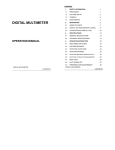
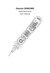
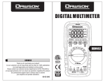
Dawson DSM101N Digital Multimeter with Environmental Tester User’s Manual TABLE OF CONTENTS LIMITED WARRANTY AND LIMITATION OF LIABILITY ..................................................... 3 Out of the BoxError! Bookmark not defined. Accessories ................................................. 4 Safety Information ...................................... 7 Certification ................................................ 7 INTRODUCTION ........................................... 8 Overview ..................................................... 8 Figures and Components ............................ 9 Buttons and Components ....................... 10 Display Description................................. 12 USING THE METER ..................................... 14 Preparation ............................................... 14 DC/AC Voltage Measurement ................... 19 Frequency Measurement .......................... 21 Duty Measurement ................................... 21 DC/AC Current Measurement ................... 22 Resistance Measurement .......................... 23 1 Capacitance Measurement ....................... 24 Diode ......................................................... 25 Continuity .................................................. 26 Relative Humidity Measurement (%RH) ... 27 Temperature Measurement (with ThermoResistor) .................................................... 28 Temperature Measurement (with Thermocouple) .......................................... 29 Sound Level Measurement (dB) ................ 30 Luminance Measurement ......................... 31 SPECIFICATIONS ........................................ 34 General Specification ................................ 34 Technical Specifications ............................ 35 MAINTENANCE AND REPAIR ..................... 46 Repair ....................................................... 46 Test Leads Replacement ........................... 46 Replace Batteries ...................................... 47 Replace Fuse ............................................. 47 CONTACT DAWSON ................................... 48 FEATURES ...................................... Back Page 2 LIMITED WARRANTY AND LIMITATION OF LIABILITY This instrument from Dawson Tools Inc. will be free from defects in workmanship and material for three years from the date of original purchase. This warranty does not cover defects resulting from damage caused by the user such as drops, neglect, misuse, unauthorized alteration, usage outside of specified conditions, contamination, or improper repair/maintenance. To receive service on the instrument if it becomes necessary during the warranty period, contact your nearest Dawson authorized service center at (800) 898-6991 or visit www.DawsonTools.com to obtain a return authorization (within the US only). A return authorization is necessary before returning any instrument to Dawson; no service will be provided without a return authorization. The user is responsible for properly packing the unit and charges such as shipping, freight and insurance charges. The extent of Dawson's liability is limited solely to the repair/replacement of the instrument. The above warranty in its entirety is inclusive and no other warranties, written or oral, are expressed or implied. Out of the Box Check the Meter and accessories thoroughly before using the Meter. Contact your local distributor if the Meter or any components are damaged or malfunction. 3 Accessories Test Leads Thermocouple 1.5V AAA Battery User’s Manual 1set 1pc 3pcs Safety Information WARNING TO REDUCE THE RISK OF FIRE, ELECTRICAL SHOCK, PRODUCT DAMAGE OR PERSONAL INJURY, PLEASE FOLLOW THE SAFETY INSTRUCTIONS DESCRIBED IN THE USER MANUAL. READ THE USER MANUALS BEFORE USING THE METER. WARNING TO ENSURE SAFE OPERATION AND LIFE OF THE METER, DO NOT PLACE THE METER IN ANY ENVIRONMENT WITH HIGH PRESSURE, HIGH TEMPERATURE, DUST, EXPLOSIVE GAS OR VAPOR. 4 5 Avoid shaking, dropping or any kind of impacts when using or transporting the Meter. To avoid electric shock or personal injury, repairs or servicing not covered in this manual should be performed only by qualified personnel. Avoid direct exposure to sunlight to ensure extended life of the Meter. Do not place Meter in a strong magnetic field; this may cause false readings. Use only the batteries indicated in the Technical Spec. Avoid exposing batteries to humidity. Replace batteries as soon as the low battery indicator appears. Please keep the original packing for future shipping purposes (ex. Calibration) After opening the box, check for any damage during delivery. Safety Symbols on the Meter Important safety information, please refers to the user manual Earth ground Indicates compliance with requirements for double insulation Possible of high voltage Fuse must be replaced with ratings specified in the manual. Important Safety Information 6 Never use the Meter to measure voltages that might exceed 1000V DC/750V AC above earth ground. Always be careful when working with voltages above 60V DC or 30V AC RMS. Keep fingers behind the probe barriers while measuring. Never connect the Meter leads across a voltage source while the rotary switch is in the resistance, diode or continuity mode. Doing so can damage the Meter. Do not perform resistance, diode and continuity measurements on powered circuits. Inspect test leads and probes for cracks, breaks or crazes on the insulation before using the Meter. Repair or maintenance should be implemented by trained personnel. Certification 7 CAT II: This meter has meet IEC1010-1 standard with an overvoltage category (1000V CAT II) and pollution degree 2. CAT III: This meter has meet IEC1010-1 standard with an overvoltage category (600V CAT III) and pollution degree 2. The Meter is compiled to EMC requirements. Introduction Overview The DSM101N is a portable, multifunction digital multimeter featuring a large three line backlight LCD screen. Basic functions include: AC/DC voltage, AC/DC current, resistance, capacitance, frequency and duty cycle measuring. It also features a thermocouple, ambient temperature, relative humidity, sound level and luminosity measurements. The retractable stand is ideal for travel and office use. This DSM101N is truly an All-inOne meter that is ideal for both professional and hobbyists. 8 Figures and Components Front Panel 9 Buttons and Components 1. 2. 3. 4. 5. 6. 7. 8. 9. 10. 11. 12. 13. 14. 15. 16. 17. 10 LCD (liquid-crystal display) RANGE Button REL Button HOLD/B.L Button Hz/Duty Button Panel Rotary Switch 10A Input Jack mA/ µA/Temp Input Jack COM Input Jack V/Hz/ /Ω/ Input Jack OFF – Power off SELECT Button °C/°F Switch Humidity & Temperature sensor Light Sensor Microphone Buttons and Components Description °C/°F Button Hz/Duty Button HOLD/B.L Button SELECT Button Switch units between °C and °F Switch between Hz/Duty Hold reading or hold the button to control backlight Switch between DC/AC or between RANGE Button REL Button Rotary Switch 10A Input Jack mA/ µA/Temp Input Jack /Ω/ / Choose auto or manual range Relative measurement To select different functions Input for current between 0 ~ 10A Input for current from 0~400mA and temperature V/Hz/ /Ω/ Input Jack COM Humidity Sensor Light Sensor 11 Input for voltage, resistance, frequency, duty cycle, capacitance, diode, and continuity measurement. Common terminal To measure humidity To measure lux Display Description 1. 2. 3. 12 Temperature Indicator Humidity Indicator Main Screen ~ Ac Dc H REL Auto °C °F %Rh F Ω V A Hz % dB Lux x10 n, µ, m, k, M 13 Alternating Current Direct Current AC Or DC Diode Buzzer Hold Relative Measurement Auto Range Low Battery Indicator Celsius Fahrenheit Relative Humidity Units Farad (capacitance) Ohm (Resistance) Volt (Voltage) Ampere (Current) Hertz (Frequency) Duty Cycle Decibel Iluminance Unit Decuple Nano, Micro, Milli, Kilo And Mega Using the Meter Preparation Switch on the power by turning the rotary switch. If the battery voltage is lower than 3.6V, the “ ” symbol will appear and the batteries should be replaced. The “ ” symbol next to the input lead shows that the input voltage or current should not exceed the specified value in order to protect the internal circuit from damage. Turn the rotary switch to the required function and range to be measured. Under the manual mode, choose the highest range when the value to be measured is unknown. When making connection, connect the common test lead first and then the powered test lead. Removed the charged test lead first when disconnecting. 14 Readings Hold Press “HOLD/B.L” button to hold the readings of current measurement. Press “HOLD/B.L” button again to release the hold. Switch Functions Press the "SELECT" button to switch between AC and DC measurements in the current and voltage. Press the “SELECT” button to switch between resistance, diode, continuity and capacitance measurements. Switch Ranges When the Meter is turned on, it is at the auto range mode for current, voltage and resistance measurement by default. 15 Press the "RANGE" button for manual range mode. The range will go up one level after each press and return to the lowest level when the highest level is reached. Hold the "RANGE" button for two seconds to return to auto range. Switching Between Frequency/Duty Press the “Hz/DUTY” button at the frequency range to switch between frequency and duty measurements. When the Meter is in the voltage and current modes, press the “Hz/DUTY” button to measure the frequency of the voltage or current signal. Another press on the “Hz/DUTY” button will change it into the Duty range for measuring the duty cycle of the voltage or current signal. Press the “Hz/DUTY” again go back to normal mode Switching To Relative Measurement Press the “REL” button to enter the relative measurement mode. The instantaneous reading when the button is pressed will is stored in memory as the reference value for later measurements. The displayed reading is the difference between the input value and stored reference value. I.e. REL (present reading) = input value reference value. 16 NOTE: 17 Press the “REL” button again to cancel the relative measurement function. Pressing the “REL” button in HOLD mode will cancel the HOLD function and the measurement value will be stored in the memory as the reference. The readings displayed will be the difference between the input value and the reference value. Press the “RANGE”, “SELECT” buttons or turning the rotary switch will cancel the relative measurement function and resume normal measurement. The REL symbol on the display will disappear. OL triggering: Under the REL mode, OL (over limit) will flash if the input value exceeds the range. Press the “REL” button again to cancel the relative measurement function. The Meter will enter the manual range mode after the “REL” button is pressed. REL mode is not available for Hz/Duty range. The REL measurement cannot be performed when in OL. Backlight Press the “HOLD/B.L” button for two seconds to turn on backlight. The backlight will go off automatically after 10 seconds. Press the “HOLD/B.L” button for two seconds again to manually turn off the backlight. NOTE: Backlight requires a large working current, although the Meter backlight will be off automatically after 10 seconds, frequent use of the backlight will shorten the life of the batteries. Do not use the back light unless necessary. When the battery voltage is ≤3.6V, “ ” (battery low) will appear on the LCD. When the backlight is on, even if the batter is ≥3.6V, “ ” may appear because of its large working current which causes the voltage to drop. (The accuracy of the measurement cannot be assured when the “ ” symbol appears.) In this case no battery replacement is necessary. Only do so when “ ” appears when the back light is not being used. 18 Auto Power Off If there is no operation (exclude °C/°F button) within any thirty minute period, the meter will auto off. Turn the rotary switch or press any of the “HOLD/B.L”, “SELECT”, “RANGE”, “Hz/DUTY” or “REL” button to resume operation of the Meter under auto power off mode. To disable the auto power off function, hold the “SELECT” button when turning on the Meter. DC/AC Voltage Measurement WARNING USE CAUTION WHEN MEASUREING HIGH VOLTAGE CIRCUITS TO AVOID ELECTRICAL SHOCK AND INJURY. DO NOT TEST VOLTAGES HIGHER THAN DC 1000V or AC 750V. 19 Plug the black test lead into the “COM” jack and the red test lead into the “V” jack. Set the rotary switch to the “V ” position. NOTE: o o o 20 Press the "SELECT" button to switch to DC or AC measurement. Press the “RANGE” button to choose the auto range or manual range mode. Connect the test leads to the voltage source or load for measurement. Read the numbers on the main indicator of the LCD. The polarity symbol denotes the polarity of the end connected by the red test lead. At small voltage ranges, unsteady readings will appear before the test leads make contact with the circuit. This is normal since the Meter is highly sensitive. When the test leads are connected to the circuit, the true reading will be shown. Under the manual range mode, when ‘OL’ or ‘-OL’ is shown on the LCD, it means the measurement has exceeded the allowable range. A higher range should be selected. Under the manual range mode, when the scale of the value to be measured is unknown, select the highest range first and lower the range accordingly. Frequency Measurement Plug the black test lead into the” COM” jack and the red test lead into the “Hz” jack. Set the rotary switch to the “Hz” position or press the “Hz/DUTY” button in the AC/DC V range to switch to Hz measurement. Connect test leads to the two ends of the source or load for measurement. Read the numbers on the main indicator of the LCD. Duty Measurement 21 Plug the black test lead into the” COM” jack and the red test lead into the “Hz” jack. Set the rotary switch to the “Hz” position. Press the "Hz/DUTY" button to switch to DUTY measurement or press the “Hz/DUTY” button in the AC/DC V mode to switch to DUTY measurement. Connect test leads to two ends of the source or load for measurement. Read the numbers on the display. DC/AC Current Measurement WARNING USE CAUTION WHEN MEASUREING HIGH VOLTAGE CIRCUITS TO AVOID ELECTRICAL SHOCK AND INJURY. DO NOT TEST VOLTAGES HIGHER THAN DC 1000V or AC 750V. 22 Plug the black test lead into the “COM jack. When the current to be measured is under 400mA, plug the red test lead into the “µA/ mA” jack; when the current to be measured is over 400mA but under 10A, plug the red test lead into the “10A” jack. Set the rotary switch to the “A ” or “mA ” or “µA ” range position. Press the "SELECT" button to switch between DC and AC measurements. Press the “RANGE” button to choose auto range or manual range mode. Connect the test leads to the circuit. Read the numbers on the display. The polarity symbol denotes the polarity of the red test lead. NOTE: o o o Under the manual range, when ‘OL’ or ‘-OL’ is shown on the LCD, it means the measurement has exceeded the allowable range; a higher range should be selected. Under the manual range, when the scale of the value to be measured is unknown, select the highest range first and then lower the range accordingly. “ ” indicates the maximum current of the mA jack is 400mA and the maximum current of the 10A jack is 10A. At the 10A jack, current exceeding the limit will blow the fuse. Resistance Measurement WARNING TO AVOID ELECTRICAL SHOCK AND INJURY POWER OFF THE CIRCUIT AND DISCHARGE THE CAPACITANCE BEFORE MEASURING RESISTANCE. 23 Plug the black test lead into the “COM” jack and the red test lead into the “Ω” jack. Set the rotary switch to the “Ω” position. The mode is set to measure capacitance by default. Press the “RANGE” button to choose auto range or manual range mode. Connect the test leads to the ends of the resistor or circuit. Read the numbers on the LCD. NOTE: At the manual range mode, when ‘OL’ or ‘-OL’ is shown on the LCD, it means the measurement has exceeded the range and a higher range should be selected. When the input is open, ‘OL’ is displayed on the LCD to indicate overload. For measuring resistance above 1MΩ, it may take a few seconds to get a steady reading. This is normal for high resistance measurement. Capacitance Measurement WARNING TO AVOID ELECTRICAL SHOCK AND INJURY POWER OFF THE CIRCUIT AND DISCHARGE THE CAPACITANCE BEFORE MEASURING CAPACITANCE. 24 NOTE: o o Plug the black test lead into the ”COM” jack and the red test lead into the “ ” jack. Set the rotary switch to the “ ” range position. Press the "SELECT" button to switch to “ ” measurement. After fully discharging the capacitor, connect the test leads to the two ends of the capacitor for measurement. Read the numbers on the LCD. It takes some time to stabilize reading when measuring high capacitance. (~30 seconds for the 200μF range) Sometimes reading may be shown even when the test leads are not connected to the circuit. In such case, press the “REL” button to reset the reading and take the measurement again. Diode 25 Plug the black test lead into the ”COM” jack and the red test lead into the “ ” jack. Set the rotary switch to the “ ” range position. Press the "SELECT" button to switch to “ ” Diode measurement. NOTE: o o Connect the red test lead to the anode and the black test lead to the cathode of the diode for testing. Read the numbers on the LCD. The Meter will show approximate forward voltage drop of the diode. When the test leads are reversed or opened, ‘OL’ will appear on the LCD. Continuity WARNING TO AVOID ELECTRICAL SHOCK AND INJURY POWER OFF THE CIRCUIT AND DISCHARGE THE CAPACITANCE BEFORE TESTING CONTINUITY. Plug the black test lead into the “COM” jack and the red test lead into the “ 26 ” jack. Set the rotary switch to the “ ” range position. Press the "SELECT" button to switch to “ ” continuity measurement. Connect the test leads to two ends of the circuit. If resistance of the circuit is less than 40Ω the built-in buzzer will sound. NOTE: If the test leads are open or resistance of the circuit is over 400Ω, “OL” will appear on the LCD. Relative Humidity Measurement (%RH) This function is used for measuring ambient humidity around the Meter. Turn the rotary switch to any position other than OFF. Current ambient humidity will is shown on the humidity display (%RH). NOTE: o Humidity sensor is placed inside the front of the Meter and therefore it may take a longer time to reach balance with the environment being measured. Also, it takes a longer intermission time, about 20 seconds, for sampling and the Meter has to be exposed to the environment for a longer time to get accurate readings. Hence it is not suitable for measuring rapidly changing ambient humidity. o It will take some time for a steady %RH reading when the ambient humidity changes. 27 Temperature Measurement (With build in Thermo-Resistor) This function is used for measuring the ambient temperature around the Meter. Turn the rotary switch to any position other than OFF. The current ambient temperature will be shown on the temperature indicator of the LCD. Press the "°C/°F" button to switch between °C and °F measurement. NOTE: o Temperature sensor (thermo-resistor) is placed inside the front of the Meter and therefore it may take a longer time to reach thermal balance with the environment. Also, it has a longer intermission time, about 20 second, for sampling and the Meter has to be exposed to the environment for a longer time for accurate readings. Hence it is not suitable for measuring rapidly changing ambient temperature. o Working temperature of the Meter is 32 ~ 104°F. If exposed to an environment beyond 28 32 and 104°F, the Meter may show a wider range of temperature measurement, but the accuracy cannot be ensured and may damage the Meter. Temperature Measurement (With Thermocouple) WARNING TO AVOID ELECTRICAL SHOCK AND INJURY POWER OFF THE CIRCUIT AND DISCHARGE THE CAPACITANCE BEFORE MEASURING TEMPERATURE 29 Turn the rotary switch to “TEMP” position, “OL” is displayed. Plug the red end of the ‘K’ type thermocouple into the “TEMP” jack and black end into the “COM” jack. Touch the surface of the object or area with the thermocouple for measurement. Press the "°C/°F" button to choose °C or °F measurement. Read the result on the LCD. NOTE: Temperature compensation circuit is placed inside the front part of the Meter. It may take a longer time to reach thermal balance. The Meter should be exposed to the environment for a long period for accurate reading. Sound Level Measurement (dB) WARNING AVOID ELECTRICAL SHOCK AND INJURY. DO NOT CONNECT THE TEST LEADS. Turn the rotary switch to the “dB” position. Point the sensor located in the front of the Meter to the sound source. The sound level in dB will be shown on the LCD. NOTE: Strong wind (over 10m/sec.) striking on the microphone may cause misreading. A windscreen should be placed in front of the microphone in such circumstances. 30 Luminance Measurement WARNING AVOID ELECTRICAL SHOCK AND INJURY. DO NOT CONNECT TEST LEADS. Turn the rotary switch to the “Lux” or “×10Lux” position. Point the sensor located in the front of the Meter at the light source. Read the result on the LCD. NOTE: 1 )When “OL” is displayed, choose a higher range. Ex. x10 Lux. 2)Spectral sensitivity characteristic: Relative Sensitivity (%) 100 80 60 40 20 400 500 600 700 800 900 1000 Wave Length (nm) Most suitable for visible light (400~700nm) detection 31 3)Recommended luminance: Location Home Wardrobe, Bedroom, Lavatory Stairway, Corridor Living Room, Bathroom, Kitchen Writing, Working Area Artisanry, Sewing Office Conference Room, Reception Room Administrative Area Typing Area Factory Packing, Passage Area Assembly Line Inspection Work Electronic Parts Assembly Line Hotel Public Area, Restroom Reception, Front Desk Shop 32 Lux 70~150 70~150 200 ~ 750 500~1000 750~2000 200 ~ 750 700 ~ 1,500 1000 ~ 2,000 150 ~ 300 300 ~ 750 750 ~ 1,500 1,500 ~ 3,000 100 ~ 200 200 ~1,000 Stairway, Corridor Display Window Hospital Ward, Warehouse Examination Room Operating Room, Emergency Room School Auditorium, Indoor Gym Classroom Laboratory, Library 150 ~ 200 1,500 ~ 3,000 100 ~ 200 300 ~ 750 750 ~ 1,500 100 ~ 300 200 ~ 750 500 ~ 1,500 Appendix: Conversion between luminance and light intensity: E=I/r2 Where: E --- luminance, unit: Lux; I --- intensity of light source, unit: cd; r --- distance between illuminant surface of light source and light detector, unit: m. When making measurement, the shortest distance between the illuminant surface of the light source and the light detector should be larger than 15 times the 33 maximum size of the illuminant surface of the light source (or the light sensor). Specifications General Specification 34 Auto range and manual range. Overload protection is provided for all modes. Maximum voltage between terminals and earth ground: 1000V DC or 750 VAC Operating altitude: max. 2000 meters (7000 ft.) Display: LCD Maximum value display: 3999 Polarity indication: automatic; ‘-‘ for negative polarity. Overload indication: ‘0L’ or ‘-0L’ Sampling time: approx. 0.4 second per sample Function and Unit display Auto power off time: 30 min Resettable fuse: F1 500mA/250V Fuse protection: F2 10A/250V (quick acting) Power Supply : 1.5V×3 AAA batteries Battery low indication: “ ” on LCD Temperature Index: < 0.1× Accuracy /°F Operating Temperature: 0°C to 40°C (32°F to 104°F) Storage Temperature: -10°C to 50°C (10°F to 122°F) Dimension: 195×92×55mm (7.7x3.6x2.17 in.) Weight: approximate 400g (14oz) including batteries Technical Specifications DC Voltage Range Resolution Accuracy 400mV 0.1mV ± (0.7% of reading + 2 4V 1mV digits) 40V 10mV 400V 100mV 1000V 1V Input Impedance: 10MΩ Overload protection: 400mV range: 250V DC or rms AC, 4V-1000V ranges: 1000V DC or 750V rms AC. Max. input voltage: 1000V DC or 750V rms AC 35 NOTE: o At small voltage ranges, unsteady readings will appear before the test leads make contact with the circuit. This is normal since the meter is highly sensitive. When the test leads connect to the circuit, the true reading will be shown. AC Voltage Range Resolution Accuracy 400mV 0.1mV ± (0.8% of reading + 3 digits) 4V 1mV 40V 10mV 400V 100mV 750V 1V ± (1.0% of reading + 3 digits) Input Impedance: 10MΩ Overload protection: 400mV range: 250V DC or rms AC, 4V-750V ranges: 1000V DC or rms 750V AC. Max. input voltage: 1000V DC or rms 750V AC Frequency range: 40 to 400Hz Response: Average 36 NOTE: o At small voltage ranges, unsteady readings will appear before the test leads make contact with the circuit. This is normal since the meter is highly sensitive. When the test leads connect to the circuit, the true reading will be shown. DC Current Range 400μA 4mA 40mA 400mA 4A 10A Resolution 0.1μA 1μA 10μA 100μA 1mA 10mA Accuracy ±(1.2% of reading + 3 digits) ±(2.0% of reading + 10 digits) Overload protection: μA, mA ranges: resettable fuse F1, 500mA/250V 10A range: F2, 10A/250V fuse (quick acting). Max. input current: mA jack (µA ranges): 4mA, mA jack (mA ranges): 400mA, 10A jack: 10A voltage drop: 37 400μA ranges: 40mV, 4000μA ranges: 400mV, 40mA ranges: 40mV, 400mA ranges: 400mV, 4A range: 40mV 10A range: 100Mv AC Current Range Resolution Accuracy 400μA 0.1μA 4mA 1μA 40mA 10μA ±(1.5% of reading + 5 digits) 400mA 100μA 4A 1mA 10A 10mA ±(3% of reading + 10 digits) Overload protection: μA, mA ranges: resettable fuse F1, 500mA/250V 10A range: F2, 10A/250V fuse (quick acting). Max. input current: mA jack (μA ranges) : 4mA, mA jack (mA ranges) : 400mA, 10A jack: 10A voltage drop: 400μA ranges: 40mV, 4000μA ranges: 400mV, 38 40mA ranges: 40mV, 400mA ranges: 400mV, 4A range: 40mV 10A range: 100mV Frequency range: 40 to 400Hz Response: Average Resistance Range Resolution Accuracy 400Ω 0.1Ω 4kΩ 1Ω 40kΩ 10Ω ±(1.2% of reading + 2 digits) 400kΩ 100Ω 4MΩ 1kΩ 40MΩ 10kΩ ± (2.0% of reading + 5 digits) Open circuit voltage: ~0.25V Overload protection: 250V DC or rms AC Capacitance Range Resolution Accuracy 40nF 10pF 400nF 0.1nF 4μA 1nF ±(3.0% of reading + 3 digits) 40μF 10nF 100μF 100nF - Overload protection: 250V DC or rms AC 39 Frequency Range 9.999Hz 99.99Hz 999.9Hz 9.999kHz 99.99kHz 199.9kHz >200kHz Resolution 0.001Hz Accuracy ±(2.0% of reading + 5 digits) 0.01Hz 0.1Hz 1Hz 10Hz 100Hz reference only ±(2.0% of reading + 5 digits) ±(2.0% of reading + 5 digits) By Hz mode: Measurement range: 0 ~ 200kHz Input voltage range: 0.5V – 10V rms AC (higher input voltage at higher frequency) Overload protection: 250V DC or rms AC By V mode: Measurement range: 0 ~ 40kHz Input voltage range: 0.5V – 750V rms AC (higher input voltage at higher frequency) Input Impedance: 10MΩ Max. input voltage: 1000V DC or 750V rms AC By μA, mA or A mode: Measurement range: 0 ~ 40kHz 40 Input current range: ≥ 1/4 range rms AC (higher input voltage at higher frequency) Max. input current: mA jack (μA ranges): 4mA, mA jack (mA ranges): 400mA, 10A jack: 10A Overload Protection: μA, mA ranges: resettable fuses F1, 500mA/250V 10A range: F2, 10A/250V fuse (quick acting). NOTE: When measuring frequency, the range in “Hz” mode is larger than that in “V” or “A” mode. Also note that the value measured beyond the range given above is for reference only. Duty Range Resolution Accuracy 0.1 - 99.9% 0.1% ± 3.0% By Hz mode: Frequency response: 0 ~ 200kHz Input voltage range: 0.5V – 10V rms AC (higher input voltage at higher frequency) Overload protection: 250V DC or rms AC (higher input voltage at higher frequency) 41 By V mode: Frequency response: 0 ~ 40kHz Input voltage range: 0.5V – 600V rms AC (higher input voltage at higher frequency) Input Impedance: 10MΩ Max. Input Voltage: 1000V DC or 750V rms AC By μA, mA or A range: Frequency response: 0 ~ 40kHz Input current range: ≥1/4 of the rms AC for the range (higher input voltage at higher frequency) Max. input current: mA jack(μA ranges): 4mA, mA jack(mA ranges): 400mA, 10A jack: 10A Overload protection: μA、mA ranges: resettable fuses F1, 500mA/250V 10A range: F2, 10A/250V fuse (quick acting). NOTE: The range by duty of the Hz mode is larger than that of the voltage or current mode. 42 Relative Humidity (on RH and humidity display) Range Resolution Accuracy 20 - 95% 0.1% ± 5.0%RH Operating temperature: 0°C to 40°C Sampling Period: ~20s. Temperature Temperature (on sensor, thermo resistor NTC and temperature display) Range Resolution Accuracy °C 0.1°C 0°C to 40°C ± 2°C °F 0.1°F 0°F to 40°F ± 2°F Sampling Period: ~20s. Temperature (on sensor, thermocouple and main Display) Resolution Accuracy -20°C to 0°C ± 5.0% of reading or ± 3°C 0°C to 400°C ± 1.0% of reading °C 1°C or ± 2°C 400°C to 1000°C 43 ± 2.0% of reading -4°F to 32°F °F 1°F 32°F to 752°F ± 5.0% of reading or ± 6°F ± 1.0% of reading or ± 4°F ± 2.0% of reading 752°F to 1832°F Overload protection: resettable fuses F1 500mA/250V. Sound Level(dB) Range 40-100dB Resolution 0.1 dB Accuracy ± 3.5%dB at 94dB, 1kHz sine wave Typical instrument frequency range: 100 ~ 8000Hz Luminance (Lux) Range Resolution Lux 1 Lux (4000) ×10Lux 10Lux (40000) Repeatability: ±2%. 44 Accuracy ±(5.0% of reading + 10 digits) at color temp. 2856K , calibrated to standard incandescent lamp Diode Test Resolution 1mV Function Displaying approximate forward voltage of diode Forward DC current ~1mA Reversed DC voltage ~1.5V Overload Protection: 250V DC or rms AC Continuity Test Function Built-in buzzer will sound if resistance is lower than 40Ω. Open circuit voltage ~0.5V Overload Protection: 250V DC or rms AC 45 Maintenance and Repair Repair Please follow these steps closely if the Meter is not functioning properly: Check batteries; replace with new batteries if low battery indicator “ ” appears. Follow User’s Manual to confirm all procedures. Before sending Meter back for repair, include a description of the problems encountered. Remove batteries and pack Meter well to avoid damage in delivery, Dawson does not cover damage due to delivery. Repair or service not covered in this manual should be performed only by the authorized service center or qualified personnel. Test Leads Replacement WARNING REPLACE THE TEST LEADS WITH IDENTICAL OR COMPATIBLE LEADS. LEAD SPEC:1000V 10A. Replace new leads if the current leads are worn. 46 Replacing Batteries Follow these steps to replace batteries: Turn off the Meter. Pull up the stand, loosen the battery compartment door screws, pull from the lower part of the cover and remove the cover from the case. Remove the batteries and replace the batteries with new batteries. Reattach the battery compartment door to the case bottom and tighten the screws. Replacing Fuse Fuses rarely need replacement. Almost all blows are the result of operation error. Loosen the battery compartment door screws like in the Replace Batteries. Replace the blown fuse with one at the specified rating. Put the battery cover back and tighten the screws. 47 Contact Dawson Dawson Tools, Inc. 1142 S. Diamond Bar Blvd., #858 Diamond Bar, CA 91765 Phone: (310) 728-6220 www.DawsonTools,com Do not recycle 48 (Back Page) Features 49 LCD Display Auto and Manual Ranging Auto Power Off Diode Test Audible Continuity Back Light Data Hold Low Battery Indicator