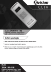
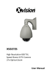
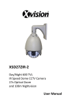
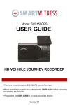
1
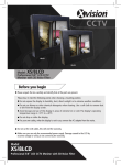
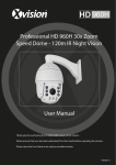
CCTV
XA200 System
Model: XA001
Audio Door Entry System
with Single Phone
Model: XA002
Audio Door Entry System
with Two Phones
Before you begin
• Please unpack the box carefully and identify that all the parts are present.
• Do not cut the cables, this will void the warranty.
• Make sure you use only the recommended power supply. Damage caused to the unit by
incorrect voltage or wiring is not covered by the warranty.
Model:
XA001/XA002
Audio Door Entry System with
Single/Two Phone(s)
Thank you for purchasing this Xvision Audio Door Entry System. Before
operating this product, please read this instruction manual carefully.
1. Safety Precautions
2. Product Description
2
The XA001 and XA002 are excellent value Audio Door Entry Systems,
designed for ease of use and maximum reliability. Both systems include a
Call unit with speaker and microphone. The XA001 comes with a single
Phone unit and the XA002 comes with two Phone units. Both systems
include a Door Release button and allow 2-way communication with the
Call unit.
3. Features
Easy to use, single button Phone unit(s) for Call and Door Release for
remote opening of door/gate
XA001 operates on 2+2 wiring (2 for power, audio and 2 for release),
XA002 operates on 3+2 wiring (3 for power, audio and 2 for release).
Phone unit operates on 220V to 240V AC power.
Call unit powered via the Phone unit(s)
Phone unit requires Internal Wall mounting.
Call unit can be mounted externally
4. Contents
XA001 System:
Phone unit
Wall Plugs
Call unit
Wall Plugs
Mounting
Screws
Mounting
Screws
Fixing
Screws
+
XA002 System - includes an additional Phone unit
Wall Plugs
Phone unit 2
Mounting
Screws
3
5. Controls
PHONE UNIT
CALL UNIT
6
1
7
2
8
3
9
4
10
5
4
1. Handset
Used for two-way communication
with callers.
6. Speaker
Used to transmit sound from
Phone unit.
2. Power indicator
Lights when power switch is in
‘ON’ position.
7. Microphone
Used to speak into for two-way
communication with Phone unit
3. Chime Switch
Used to adjust the chime sound on
the Phone unit.
8. Call Button
Press to call the Phone unit
4. Door Release Button
Used to unlock an electronic door
locking system.
5. Handset cord
Flexible cord between Phone
handset and unit.
9. PVC Cover
Can be used to label unit for
identifying the premises
10. Mounting Screw holes
Remove PVC Cover to access
the holes during installation
6. Installation
A. Installation of the Phone unit(s)
1. Choose a suitable location to mount the
phone(s). The handset should be mounted 1.50
to 1.70m from floor level.
2. Fix the mounting plate (detachable from unit)
to the wall, using the screws supplied. Drill a
hole in the centre of the mounting plate large
enough to feed the cables through.
5
3. Connect the wires from the door entry phone
to the connector on the back of the handset.
4. Attach the phone unit to the mounting plate by
placing the handset over the four bracket hooks
and sliding the unit down.
...continued overleaf
6. Installation (continued)
5. Connect the handset cord to the connector on
the bottom of the handset
6. Place the handset in the cradle to complete the
installation.
6
B. Installation of the Call unit
1
3
2
4
5
1. Ensure weatherproof cover is fitted to the Call unit.
2. Determine the position of the unit and install the Wall plugs.
3. Drill a hole in the centre of the Wall Plugs large enough to feed the
cable through.
4 Secure the unit using the screws supplied. (Remove PVC Cover to
access mounting holes).
5. Re-attach the PVC cover to complete installation.
6. Installation- Notes
Use the following points to help you complete a trouble free
installation:
1. Treat the unit with care
Do not disassemble the unit as you may damage the internal
components. Dropping the unit or banging it against another
object may cause the unit to malfunction.
2. Do not touch the internal components
Do not touch the internal components of the unit. There are no user
serviceable parts inside.
3. Avoid contact with water
Install the Phone unit where it can be kept dry. If the units gets wet
accidentally, turn off the power and contact your dealer. The Call unit
is weatherproof and can be mounted externally, though care should
be taken not to submerge the unit in water.
4. Install the unit away from possible sources of interference
Avoid running cables close to other wiring installations or
electrical equipment. These may cause interference to the audio
images. Relocate the cabling or find a new location.
5. Check the ambient temperature and humidity
Avoid using the camera in an area where the temperatures are
outside the range specified. The quality of images may deteriorate
and internal components may be affected.
7
7. Operation
Turn mains power switch ON, use the side switch to adjust chime sound
on the Phone unit.
1. When the visitor presses the ‘Call’ button
on the Call unit, the Phone unit will sound
a ‘chime’ tone to announce that a visitor is
at the door. Communicate with the visitor
using the handset.
2. After communicating with the visitor you
can press the ‘Door Release’ button to
activate the door lock and open the door.
8
3. Simply replace the handset when the
conversation is over
8. XA001 System & Wiring Diagram
XA001: Audio Door Entry Call unit / Single Phone unit
System Diagram
Wiring Diagram
9
9. XA002 System & Wiring Diagram
XA002: Audio Door Entry Call unit / Two Phone units
System Diagram
10
Wiring Diagram
Specifications
Model:
XA001/XA002
Operating Voltage:
Phone Unit: 220-240V AC
Call Unit: 9V DC, 20mA
Installation:
Call Unit: 2 wire cabling
XA001 Phone Unit: 2 wire cabling
XA002 Phone Units: 3 wire cabling
Call Tone:
Chime sound
Communication Type:
With handset communication
Max. Wiring Distance:
150 metres
(0.8mm copper wire)
Operating Temperature: -10°C to +55°C
Weight:
Phone Unit: 0.6kg
Call Unit: 0.45kg
Dimensions (WxHxD):
Phone Unit: 89x220x75mm
Call Unit: 80x40x30mm
11
CCTV
TECHNICAL SUPPORT:
For Technical Support for any Xvision product please contact your local
distributor.
LIMITED WARRANTY:
This product is supplied with a 1 Year warranty. The Warranty excludes
products that have been misused, (including accidental damage) and
damage caused by normal wear and tear. In the unlikely event that you
encounter a problem with this product, it should be returned to the
place of purchase.
Manufactured exclusively for:
Xvision (Europe) Group,
Head Office: London, U.K.
Email: [email protected]
Web: www.x-vision.co.uk