1
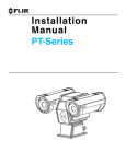
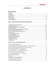
3 INSTALLATION OVERVIEW
General installation information for all SR-series cameras is given below.
If you have a question regarding installation or operation of your SR-Series camera, contact
FLIR Systems, Inc Customer Support, using the contact information at the front of this manual.
Check out our training web site (http://www.flir.com/training/) to get information on courses
offered and to learn how you can become a FLIR-authorized Installer.
Take care during installation to avoid scratching the camera lens. Do not expose the camera to
direct sun for long periods without the sun shroud installed.
3.1 Accessing the Electrical Connections
Power and
optional serial
communications
cable gland
Video cable
gland
“T” handle
Retention screws
Figure 3-1: Rear view of SR-Series camera
It is necessary to remove the rear of the enclosure in order to access the electrical connections.
The SR-Series provides electrical contacts in the form of screw-terminal jacks, allowing it to
receive 16-24 AWG tinned leads from the power supply and serial communication interface.
3.2 Ground Connection
The SR-Series cameras have grounding and surge protection to provide further immunity from
high current transients that can occur in installations that are subject to electrical storms and/or
nearby lightning events. In order to ensure CE and FCC compliance as well as to protect
against these high current events, installers are required to provide an Earth connection to a
specific connection on the camera. Note: a ground connection to the exterior of the camera (for
example, to the mounting foot) is insufficient.
427-0042-00-10 Revision 120
Copyright © 2010 FLIR Systems, Inc.
9